


Old Bill
-
Posts
1,682 -
Joined
-
Last visited
-
Days Won
33
Content Type
Profiles
Forums
Gallery
Blogs
Events
Articles
Store
Downloads
Everything posted by Old Bill
-
That is most interesting. In which part of the world did you see it? The hunt is now on for engine and gearbox. We will all keep our eyes open! Steve
-
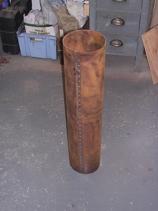
Well, the body is schemed out now and the timber has been ordered. There are some big lumps to get for the crossmembers and, as we want to put the body together over Christmas, we need to get some preparatory work done now. In particular, we want to get some paint on the crossmembers and the undersides of the floorboards so that we can just put them together. Painting upwards is a really horrible pastime so getting it done before assembly will make life a lot easier. To help the job along, I have cut some templates for Mark the Chippy to use. Right or wrong, at least they will all be the same! I have been pressing on with the silencer tube. I have decided to use just a simple lap joint along the seam so, to drill the rivet holes, I need to pull the tube circular. First job was therefore to turn up some discs and then space them out on some studding. I pulled the tube together using a torniquet and secured the ends with wires before drilling the rivet holes through both pieces. These fiendish little devices are called 'Clecos' and I got a bag of them with a model locomotive kit from the US. I just remembered that I have them and thought I would give them a go. They have proved to be wonderful! Once the hole is drilled, they are inserted using a pair of special pliers to squeeze them up. The ends come through leaving a centre wedge behind. This allows them to be pushed through the plates. When the pliers are released, the ends get a grip on the plate and a strong spring pulls them all together. Once all the holes had been drilled, I trimmed the edges of the tube to length using an angle grinder. A horrible job but my bending jig for the fuel tank made an excellent stand for the tube to stop it rolling away! Onec the edges had been cleaned up, they were pulled together and the Clecos inserted once again. The two rivets at each end were inserted and formed using the rivet squeezer previously prepared for the fuel tank. They went very well. The remainder were put in using a hammer and rivet snap. This was successful but the snap has given up and split so I must get a new one. There is another piece complete and ready to fit. It is just awaiting the castings for the ends now so I must pick them up and prepare the patterns which Barry has so kindly printed for us. A thought occurs to me. How am I going to get the baffles in now that there are 28 rivets in the way! Steve


-
Thanks Chaps for your suggestions and kind offer. I don't think that they actally troubled to joggle the edges at this time. Neither the fuel tank or silencer has any cosmetic pretensions and the original tank that I have shows no signs of having been treated this way so I think I will go with straight lap joints and just rivet along the seams. I have some holiday next week and one of the targets for the week is to drill all of the holes in the tank and tin the joints ready for assembly. There are 214 rivets all told! While we were bending the wrapper one of the miniature railway people saw what we were doing and suggested TIG welding it. Whilst that would certainly do the job, it isn't how Thornycrofts did it. Unfortunately, he couldn't quite see why I would persist with a much more labour intensive method. Oh well! Steve
-
I know they have collected a load from the Commercial Vehicle Museum but I don't know precisly what. We had a visitor who had some for his T4 engine of 1912. We now have enough information from other sources so I have not been back to investigate. Steve
-
It depends on what you want, Al. The Dennis drawings survive in the Surrey Records Office in Woking. Some of the Thornycroft drawings are with the Hampshire County Council Museums Service and some with the British Commercial Vehicle Museum. For FWD drawings, I would start with the FWD Company in Clintonville. Lots of us have odd drawings of things we have collected so this forum is a pretty good place to start too! The stuff is often out there. You just have to be persistent in looking for it! Steve
-
Hi Ben. I had not thought of that one although I know that modern fuel is evil stuff. Will it harm the running of the engine? I seem to remember that there is a patented fuel additive which consists of zinc pellets in the fuel line but can't remember the name. It was supposedly supplied to the Russians during the war to put into the lend lease aircraft fuel tanks to help burn the local fuel. I can't see it harming the joints as it will be in solid solution with the lead. Even then, the amount there will be tiny as by the time I have cleaned the surface for soldering, it will nearly all be gone. What about attacking the steel though? The poor old FWD has a welded steel tank but has been parked up for two years with half a tank full. Time we gave it an outing again. Leaded fuel is just so much better! Steve
-
And then there were two! The next bit was the wide flare in the tube where it sits on top of the cylinder block. I couldn't fit this earlier due to the centre height limit of the lathe so I glued up another block and then drilled it through to create the radii. A few moments with the band saw and some glass paper finished it off. The slot is wider than the thickness of the original blocks so I glued an extra strip on each side before tracing the end profile. Then it was more work with the gouge followed by a clean-up with the dremel and sanding drum. The blocks were glued on and left with a weight to hold them down. The paper is to stop the two halves from sticking together. A tidy up with some glass paper and it is off to the paintshop. Now I need to add pieces to the original casting to create core prints. Steve


-
Since John so very kindly loaned me the front water elbow to use as a pattern, I have been making up a core box to match it. First job was to measure up the casting and I did this by drawing around it on my drawing board using a couple of blocks to hold it horizontal and then a square to transfer the profile onto the paper. Once I had a drawing, I could transfer the profile to two blocks of MDF. I dowelled them together and then planed them to the profile transferred from my drawing. I had been puzzling over how to generate the centre holes but found that Screwfix offer an adjustable drill. I set this to 2 1/4" diameter and then had a tes run in a piece of scrap. This went well. I then took my blocks and marked out the centre lines of the casting. Note that the blocks are over-size to allow some space for the core prints. I transferred the centre lines by the age-old method of sticking a scriber through the drawing and joining the dots. Then I placed the block on the cross slide of the lathe only to discover 'the deliberate mistake'. The block was too thick for the drill to align with the split line! I remedied this by planing one of the blocks to a thinner section and was then able to dog the blocks down. I used my magnetic base as a datum to get the centre lines aligned with the axis of the lathe and then proceeded to drill my holes. Once split, it all looked very promising. I then drew in the profiles of the bores. To help my accuracy, I cut a template from a piece of mild steel. Then I started to work it out with a gouge. I soon got bored using this one and ground one of my larger lathe tools to do the job instead. Much quicker! I tidied the bore out using the Dremel with a sanding drum and a piece of glass paper. Then it was on to the other bit. This worked out OK. Now I have to do it all over again for the other side! Steve


-
Ah! The Holy Grail! What a find that would be. Good luck! Steve
-
Sounds pretty par for the course. Having hexes that tightly fit the spanners is good news though, and gives you a lot better chance of getting them out! Our engine spent ten years on a stand being regularly squirted with penetrating oil. That helped no end. Ten years is excessive and six months would probably have almost as much effect. Heat on a nut has an amazing loosening effect too and, failing that, the application of a cold chisel is a very good way of getting things moving, especially with heavily corroded nuts. We have always found that most of the stiffness is due to corrosion products and a good wire brushing of a bolt or a run through with a tap generally frees them up. Hours of fun ahead. Good luck! Steve
-
I have not heard that one before but I can see what you are doing. I am just going to trim the flat bit off as I have made it all overlength anyway! Steve
-
To be honest, Barry, I am not sure how the silencer was put together. I cut the steel to allow the ends to be hooked in opposite directions to interlock but that is looking difficult to do and I am told that it would be unlikely at this period. I am thinking along the lines of a straightforward lap joint with rivets but, now that you mention it, the end could have been joggled to give a circular interior. I may have to make a tool to do it. Further thought required! In the fuel tank, I shall just clean the steel before tinning and not worry about the zinc. It will solder well enough, I am sure. I will tin both sides of each joint before closing the rivets and then simply warm it with the gas torch and feed in a bit more solder if necessary. The proper stuff made of lead this time! Steve
-
We have done a bit more this weekend in the shape of the silencer and fuel tank. I went to the railway on Sunday where I was able to use a nice set of bending rolls. I had previously cut a piece of steel for the silencer (from a bit found in the garage, hence the surface rust!) and the rollers soon made short work of it. I just need to rivet the seam now. Next job was to bend the fuel tank. My good friend Adrian had very kindly cut me a piece of zintec sheet (zinc plated steel) to the right shape and I had spent some time marking the beginning and the end of each bend with a black felt pen. This proved to be a very valuable action. Now, the first bend was too tight for the rollers but, as I have previously posted, I made a bending jig with a piece of scaffold tube and some timber. This worked remarkably well. Then into the rollers. Actually, I was so intent on the job that I forgot to take a pic of the first bend but this is the second. We fed the sheet through the rolls almost to the line and then wound the rear roll up as far as it would go. The rolls were a perfect size for this job so at that point, we turned the handle a little until the other line went between the rolls before taking of the pressure and pulling the sheet out. A trial fit with the aid of some toolmakers clamps looked very promising so we put it back for the final bend which was done the same way. We had to have a couple of goes at it to get it in the right place but then Adrian and Matt tried the clamps again. It all looks very nice. Now all I have to do is drill 200 holes in it, tin it and rivet it all together! Many thanks to Adrian and Matt for making a job which really concerned me remarkably easy. You need your friends in this hobby! Steve


-
It is interesting that you should ask that one Andy, as Barry has just very kindly printed the patterns for the silencer ends for us. This is an original, photographed many years ago. And these are the patterns and core boxes. They are super objects and will do the job nicely. However, their surfaces have a definite texture to them which will allow the sand to get a 'key' and make them difficult to remove. Barry recommends 'Pattern Coat' ( http://www.easycomposites.co.uk/#!/patterns-moulds-and-tooling/pattern-making/composite-pattern-coat-primer.html ) which he applied to the throttle quadrant to such good effect. It builds well and with a rub down took out the printing lines nicely. Father has just bought some and I will have a go with it shortly. Steve


-
Father has been busy and I forgot to mention it! The front cover from the differential housing was missing so I made up a pattern and Dad had it cast. He has now machined it up including a felt seal groove and it is ready for the paint shop and fitting. One more down! Steve


-
Thanks Terry. I knew I should have asked you first! I am well on the way carving them out at the moment but should I give up in disgust, I will try this method. Thanks for reminding me! Steve PS. Looking forward to hearing your engine too!
-
Thanks Andy. Yes, I did think about it but as I will be brazing the ends on, I think it likely that I will mess up the heat treatment. I'm sure that SG will be fine. At the end of my last post, we were fixing the seat down. At the front are two coach bolts but the rear is secured with two straps so I have made these up. Starting off with two flat strips with holes. Then a slot and two studs. These were welded by our senior welder at work. I don't want to risk them failing whilst I am sitting on it! Finally, a couple of hours with a file finished them off. They are now in the paint shop. I have been doing all those boring things like fixing leaks in the attic and broken horseless carriages which just have to be done no matter how little one wants to. I have, however, found some time to make up the silencer baffles. I cut them out with a nibbler which is a wonderful if very frustrating tool to use. It can get anywhere but maintaining a straight line or constant curve eludes me. I don't have any to copy but there is a small picture in the parts book. Unfortunately, the book doesn't give quantities of parts but I have guessed four and spent a long time counting holes to get the right number in the plates. I think there are 117 altogether with three larger ones for the spacing bars. I used a hand vice to hold the stack of discs and drilled them through (with one out of position. Very irksome!) I screwed the stack to a board which I held in the four-jaw and turned the periphery. Something else in the box ready for use. I was fortunate to be able to attend Duncombe Park Rally near Thirsk on Sunday last where I met John Marshall and saw his J type. I had a ride and he has very kindly loaned me his spare high-level water branch from the top of the engine. Unfortunately for me, he wants it back but it will make an excellent pattern to make a copy. I just need to make up a core box. Core box is the next task, once I have worked out how to do it. Lots of MDF in this one! Will keep you posted. Steve


-
Thanks for posting Robin, but I can't find the film when I am on your page. Facebook is not my regular domain and if it doesn't have a starting handle, I am flummoxed! Steve
-
How did you cut the keyway, Ben? Steve
-
I read it as 20 nuts for £3 which is £0.15 per nut. Am I being dim? Thanks for the link though. The next lorry is a Peerless with wooden wheels and a wheelwright is a good contact to have! Steve
-
Thanks, both of you. Well worth keeping in mind for next time. Steve :-)
-
Hi Ian. Glad that you found us! Restoration is never out of the question. You have far more than we did when we started! If there is anything we can do to help, just let us know. Welcome in! Steve
-
We seem to be reaching a concensus in that they were cast but probably in steel. As I am after more toughness than grey iron but we are only driving a leather coupling, I shall have a go and get them cast in SG iron. That will be the most straightforward solution I think. Thank you for all of your thoughts. I went down to Devon at the weekend, mainly to confirm that my bonnet drawing was correct. I had originally decided on the front and rear profiles and made some plywood patterns. Unfortunately, when held up they were not quite right. I made some more which I brought down to check and these proved acceptable so the drawing has been signed off and sent to another pal to make us a bonnet. In the mean time, the timber for the floor has arrived from Mark the chippy. These are a super job and went in beautifully. However, we now needed the bolts to secure them. As we have mentioned before, old coach bolts have square nuts and these are proving surprisingly difficult to get in this country. Fortunately for us, the UNC bolts made in the USA still have square nuts so every time Time visits his in-laws, he comes back with boxes of bolts in his luggage. Goodness knows what 'Homeland Security' make of him! A quick dip in the supply found the perfect bolts so that was that problem sorted. The right hand side has a slot for the gear shift so that was cut and the second piece fitted. We couldn't resist pushing the seat forward to its correct position. A couple of rebates to clear the bolt heads and we had a floor! Dad had previously prepared the steel angles to hold the seat down so now that it was correctly positioned, we drilled the last four holes and fitted them underneath. The front is held down by coach bolts through a rail glued to the front panel. The rear has a pair of steel brackets which are currently in manufacture. The seat can be finally secured next time. Interestingly, it appears that the pedal slot will go through the full width of the front plank. I think we will leave cutting that until the pedals are finally set up. I am hoping that it will become clearer then! Steve


-
If only! Steve
-
Nice to see it running! Steve :drive:


