


Old Bill
-
Posts
1,669 -
Joined
-
Last visited
-
Days Won
33
Content Type
Profiles
Forums
Gallery
Blogs
Events
Articles
Store
Downloads
Everything posted by Old Bill
-
Just while we are on the subject, here are the plates from the Portsmouth bus of, I believe, 1919. Note the intaglio plate. Steve

-
Thanks Doug. I'll investigate further. We have set ourselves the target of getting the body well on its way over the Christmas period so, of course, we need some timber. Big Mark, our joiner pal, has very kindly offered to prepare it all for us. He did a lovely job on the Dennis and made it so easy that we think he must design flat-packs for Ikea in his spare time! Be that as it may, he has started the ball rolling by preparing the cross members for us. As you can see, they are big old chunks of timber which Mark has put together by laminating before cutting and finishing. I must say that they are a lovely job. Here is Mother giving them the seal of approval. They all have chamfers on the ends so I started off by cutting them using Grandfather's spoke shave. which he used whilst building frigates during the war. That was hard work and my hands were pretty sore by the end of the exercise! Notice that we have no work bench so the beam is supported on plastic trestles and G-clamped to one of the door pillars. Just about adequate. Very satisfying results though. The rearmost one has some extensions jointed into it so I worked out a couple of mortices using a mallet and chisel. They took a while too! The result was very satisfying though and I even got them square! Dad then started on the painting. Everything has two coats of primer, two grey undercoat and two top coat. All applied using the lorry as a work bench. How nice it would be to have some more space! All of those bits are now safely stored ready to fit. Mark has promised us the planks shortly so that Father can then get on with painting the undersides as it is so much easier doing that before they are screwed down. I need to focus on some of the body ironwork now as there is quite a lot of that although not so much as there was on the Dennis. Christmas is getting awful close! Steve


-
Our scuttle obviously had two plates. This one is the original but there are four holes present for a plate like Ian's. We think that this one is 1917 vintage. Just for completeness, here is the plate on the crank case. The engine is made up from two where most is from, we think, 1920 but the crank case with plate has an unknown history. It was nice and shiny when we put it on! Steve


-
To my eye, Ian, your radiator has the shape and proportions of that fitted to the J. Doug's has a bit more curve in the bottom tank and may well come from something later such as a Tartar. The only way to be certain would be by measurement and direct comparison with a known vehicle. The engine number can be found in three places. There is a brass plate on the crank case, a brass plate on the scuttle with engine and chassis number and the engine and chassis number are repeated on top of the front left dumb iron. If you get a matching set, then you are very lucky indeed! I can't remember our numbers but will have a look later. Our chassis had suffered damage in that area and the words 'Vehicle' and 'Engine' can be clearly read but not the actual numbers! Steve
-
It was part of the Subvention Scheme requirements that the radiator be mounted entirely above the chassis. This does make it very high and give the longer return line to the top tank. Those mounted lower down with the handle through the core would have been civilian vehicles, most probably post-war. The lower position certainly improves the visibility for the driver and shortens the return line casting. The Thornycroft radiators all have a close family resemblance so I would suggest that the best way to determine the actual model from which any radiator comes is by measurement. The X-type was essentially a lightweight J so it could easily use the same radiator but I don't know for sure either way. Our radiator was cast using patterns made from the original radiator fitted to the Hampshire Museums 1916 J so I am content that it is the right one for ours. In general terms if the radiator has a curved bottom, then it is not a Subsidy radiator but it could still be a J-type rad. Steve
-
Interesting! Is yours a low level or high level radiator? Steve
-
I don't think we are very far off with the water return and there is certainly at least one lorry with an identical component! This one is Steve Pettifer's J and is the very first one in which I had a ride. His casting does not seem to curve down so far and may be a little shorter than ours. The outside diameter is 2 3/4" so this one looks to be about 8" long. The pattern I have made is 10" so I may be a bit generous but there is an easy solution if there is a problem. This one is the charabanc at Sandy Bay near Exmouth and has a low-level radiator. This casting is noticeably shorter. Are your radiators high or low level types as that may account for the difference? Isn't it amazing that with the hundreds of photos I have, I have almost none of this casting! The only other clue I have is the parts book and, if anything, this one looks longer than mine. To be honest, I don't think we are that far off but time will tell when we try to fit it and get it in line with the casting on top of the block. Incidentally, I have just realised that we have, between us, made every single component on this page. Madness! Steve


-
The next pattern is the last one for the water system in the shape of the water return spigot on the back of the radiator. Another damn fool shap that won't sit flat on the bench! I started off by putting a piece of oak in my splendid new wood turning lathe and turning a cylinder. I then cut it into slices in the chop saw with it set to 3 1/2 ° These were glued up and a flange and core prints added to the ends. After a good rub down to hide the lobster-tail effect, ribs and filler were added and it was ready for painting. This core box, whilst simple was hard work. I started out by drilling the straight sections in the lathe again. Then, I painstakingly worked it out with gouges and glasspaper using a cardboard template to get the curve. All very tedious. Then I had to do it again! All successful in the end and finished off with Bondaprime. That is number 27 so only three left to do! Dad is off to the foundry again next week. Next report won't be patterns! Steve


-
I shall look forward to hearing your results with interest, Barry! As you mentioned, I have been making MDF dust again. Horrible stuff but it does the job. First job was the core box to go with the propshaft spider pattern so kindly printed for me. This is to put the centre hole in at 2 1/2" dia and save us a lot of metal and machining tme. Step one, glue up some blocks. Clamp to the cross-slide and drill through. The block now has a parallel hole. However, the core prints have tapered ends to locate the core better when assembling the mould. To achieve that, I bored out some blocks with a tapered hole and then stuck them onto the ends of the MDF. The timber I picked up for the blocks was an old piece of beech which I had to plane square first. A lovely piece of wood but hard as hell! Mind you, it did bore through beautifully with a glass like finish straight off the tool. They were glued on to the ends and then the whole lot was squared up on the sander. My usual two coats of Bondaprime polished with wire wool and pattern 26 is complete and ready for the foundry next week. Onto the next pattern.....


-
I did watch Guy's programme last night and rather enjoyed it. To be honest, not driving through Lincoln was eminently sensible in my view as it was awful tight for space. I find driving the lorry through crowds on a rally field is pretty scary so taking an unproven caterpillar with poor visibility through a confined space would have been foolhardy. A great shame though. Taking it to the battlefield instead was an excellent idea. My cousin, Lt Alfred Tripe, commanded 'Eclipse 2' at that battle so it meant a lot to me. Sadly Eclipse 2 was destroyed by an artillery shell exploding in the commanders position on the second day. I shall look forward to seeing 'Deborah II' in due course. Steve.
-
Thanks for that Barry. I hadn't heard of that software so I must give it a try. Always something new to learn! The bonnet is on order but we won't see it until the Spring now. In the mean time, Dad has made up the bonnet catches. They are a slightly odd arrangement as the pegs are mounted on curved brass strips. These do give a handhold for lifting the bonnet but are really too small as I can only just get two ungloved fingers behind them. Never mind. That is how Thornycrofts did it! Dad curved the strips by putting them through our small bench rollers until they matched his template. They were then clamped in the jig and the ends bent over to match. The rivet holes were drilled. The pegs were turned up and silver soldered in place before cleaning up and a final polish. They have since been painted green, as per prototype! Steve


-
Getting bored with all of this woodwork so I have cut out the exhaust flange as a brief interlude! The elbow is away being welded so, with a bit of luck, we will be putting the whole system together very shortly. Now back to pattern making! Steve


-
I think the original was a steel casting but whilst not impossible to get, steel is a lot more difficult. Our local foundry does SG iron as a matter of course so we will opt for that. Thornycrofts did not have that option of course as the stuff hadn't been invented then! I am confident that it will be OK but time will tell. Steve
-
Hi John. To be honest, I have not taken much notice of shrinkage as most of my castings are quite small and the reduction is less than the accuracy of my pattern making! I do have a shrinkage rule, however, which has inch scales oversize depending on the material for which they were intended and I have used that. A good pattern maker uses the minimum amount of metal to achieve the desired result so there is no spare available for machining back. I am just not that good! Steve
-
I think the colour change is because the filament ran out. It is certainly not critical in this application! The Patterncoat is a heavily loaded primer so there is a significant thickness to rub off which is great for giving a finish. You have to apply it briskly though as it goes off pretty quickly. Might be worth a try on other things. Steve
-
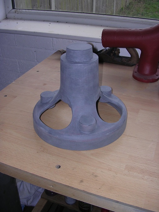
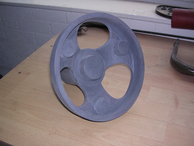
Thanks Smiffy. You are very kind but my patterns can only be classed as 'adequate'. I get what I want but I use far too much metal and they are not very robust. To see some real works of art, have a look at Tharper's patterns elsewhere on this forum. They are gorgeous! We now have 25 patterns completed and five left to do. One of those is for the propshaft spider. As you can see, this is a cussing awkward shape and would certainly test my wood-turning skills. Fortunately, Barry came to the rescue and very kindly offered to 3-d print the pattern for us on his amazing machine, an offer we accepted with alacrity! The very thin structure in the middle is temporary to support a horizontal face which is not on the base as the machine cannot lay down the fibres in mid air! They are broken off on completion. The model is not solid but has a honeycomb structure internally. Bingo! And there you have it! The boss on the end is a core print as it would be a waste to have to machine a 3" hole through the centre. The foundry told us last time that a good surface finish is essential to get the sand to release. Printed objects have a natural surface finish rather like an old 78 record and the sand can get a really good grip of it. I could see this when the silencer end patterns came back as where I had not painted the outsides of the core boxes, there were still lumps of sand attached. On Barry's recommendation, I applied two coats of 'Patterncoat' epoxy paint and rubbed back well after each. A horrible job but the surface is now very smooth. Today I am making the core box to go with it. Then that will be number 26! Many thanks Barry! Steve


-
I am sure that it is possible to weld but it would take a skilled man to do it. I suspect that it would have to be done with the lot hot as well. Good luck with that! Dad has been to the foundry today and picked up the body mount brackets and also the radiator water outlet. We are very pleased with the results but the patterns suffered a bit this time. The foundrymen said that they could have done wih a bit more draft on them and that MDF is not so good for deep patterns as it is difficult to get the screw to bite in very well when trying to pull them out Another lesson for the future! The water elbow is fine too but does show my limitations as a pattern maker. I have used far too much metal! Good job we are only doing one! More homework for Dad now. Steve


-
I should be very surprised if they had deliberately cut the down pipe to a tuned length. My experience of Thornycrofts is that they are pretty 'agricultural' in their engineering and not nearly as refined as the Dennis. Thanks for the Cast Iron Welding Services tip-off, Tomo. I actually worked in the factory right next door for seven years making rock crushing machines and could have walked there in my lunch hour! I hadn't found a job for them until now! Steve
-
As a slight aside, I have been pushing on with the exhaust system. We are fortunate to have part of the original downpipe and elbow, albeit, a bit poorly. For some peculiar reason, Thornycrofts made this elbow, like the water elbow, in the shape of a ball which strikes me as very odd. It certainly doesn't make pattern making any easier! Fortunately, we have an original although the mounting lug is snapped off. Adrian kindly sandblasted the joints for me so that I could see how they were made. We came to the conclusion that the pipes were just pushed in so removing them should be easy.... I started by cutting off the remains of a non-standard flange which was rusted beyond salvage. Then I split the first tube up the middle using the dremel and some grinding wheels. After some persistence with a cold chisel, it began to move and eventually came free. The other end was a lot harder to shift as it was slightly longer so that it protruded inside the ball and corroded on the outside jamming it in the hole. However, persistence was rewarded and out it came. I attacked the remains of the lug with a file. And then, after reference to the parts book to see what shape it should be, I cut a new one out of cast iron. I have chamfered the edges and that is now ready to weld on. I shall be seeking another favour very shortly bearing in mind that I can't even weld black mild steel! Steve


-
Neat bit of sawing. I must admit that I gave in with the Thorny and had the quadrant laser cut. It certainly took the graft out of it! Did you have the leathers made or did you find a supplier? I don't think these springs were that commen even when they were new so finding some is quite a bonus. Keep up the good work. I am certainly enjoying the reports! Steve
-
The two mounts are definitely different as there are two part numbers for them in the parts book. I am still cursing though as if they had been the same, I need only have made one pattern! We have been thinking further about the cooling system as sooner or later we are going to want to run the engine. On looking at the Carlton Colville lorry, it can be seen that the outlet from the radiator is an aluminium casting leading into a copper and brass fabricated elbow. The fabrication is original and is shown in the parts book. However, I could not see how I was going to bend a piece of two inch pipe. Fortunately, the Americans use 2" copper pipe in their household water systems and I was able to buy an elbow which I think will do the job. Whilst waiting for that to arrive, I made up the flange from a bar end of brass which Dad had on the shelf. . It quickly became clear, however, that I wouldn't be able to finish it until the cast lower elbow was fitted so that I could set the angle and cut the tube to length. Rather oddly, the elbow is an aluminiul casting in the shape of a ball with a spigot on the side. Goodness knows why Thornycrofts did that but it didn't make it any easier! The only piece of wood I had big enough to do the job was a piece of 3 1/2" oak. I put it through my bandsaw which was decidedly cruel to it. Now, a chance to use my new toy! One of our regular readers has very kindly presented me with a wood turning lathe. Time to learn some new skills! I think I need to invest in a dust extractor..... I did achieve a result though. A qick turning of the spigot and core prints on the trusty Myford (the only way I can turn straight at the moment!) and the cutting out of the flange and I had a kit of parts. I glued the spigot on but left the backplate loose so that I could set the angle to align with the fabricated elbow. Looking good! The flange was then secured in the final position. In the mean time, the core box was beckoning. First step was to glue up some blocks. Then drill the main ways. Tidy the ends out with a gouge, One core box, By this time, the main pattern had gone off so the next move was to saw it in half. I had lost some thickness due to the saw cut so I made this up with some 1/32" ply glued on to each face. It has the added bonus of giving a nice flat surface as well. A bit of filler in the corners. Dressed out with the Dremel and glass paper. Pattern number 25! Just five more to go! Steve


-
I think I can see where you are going! If you look at the very first photo of the original casting, you will see that the rear face is flat so the pattern is laid on that face for the first box to be rammed up. The core is the shape of the square hole plus a bit each end to support it so when the box is turned over and the pattern drawn, there is a squarish recess either side into which the core drops. You are right, the metal does go above the core to form the back plate of the casting. Hopefully, the core won't float off in the molten metal as that would spoil the job. At least, that is the theory. If it doesn't work, no doubt the foundry will send it back! Steve
-
I didn't want to put radii on the core print as they might tend to keep the core up if the radii there did not match. I could have added radii to the ends of the core but the longitudinal edges would be tricky. As we only want four off, I will let the moulder just scrape the edges if he sees fit. Not quite sure what you mean with the 'follow board'. I anticipate the moulder placing the pattern on its back and packing around before turning it over and drawing it straight out. The core should then just drop in, if I have my clearances right! Dad has already taken them to the foundry so we should see the results in about a fortnight. Steve
-
If we are going to do the body over Christmas, we are going to need the body mounts. These take the form of six castings bolted to the chassis rails which hold three of the cross-members. There are two sorts (why didn't they use just one?) of which one supports the end crossmembers and the other the centre one. The intermediate type of which, for some reason, we don't have a decent picture. Fortunately, I made enough sketches so I started the job with the usual pieces of MDF. Which were then glued up. The end castings have an arch which require a core to create them. This block is for the core print. It is on my trusty cross-cut saw which is a great boon to cutting straight! The core print block going into place. A bit of filler for the fillets. After an hour's dressing off with the Dremel and abrasive paper. Similarly for the end mounts. All dressed back and ready for some paint along with the core box itself. All painted with the usual two coats of Bondaprime and polished with wire wool. Those are pattern numbers twenty three and twenty four. Only six more left to do! Steve


-
Thanks Doug, If I had thought it through a bit more, I could have lined my two-gallon tins at the same time! Some of them are getting a bit tired. Oh well. Will have to do that next time. Dad has also been pushing on with the silencer. He first cleaned up the silencer ends which, with very little work, fitted the tube nicely. Thanks to Barry's excellent pattern making! He drilled the centre hole for the tie bar and three holes inside to support the baffle rods. Finally, he bored out the ends to accept the exhaust pipe itself. We then went on to assembling the baffles. These are threaded onto three rods and located in our case by split pins. I am not quite sure how they might have done this originally as I have no drawings and only a picture of a baffle in the parts book. I suspect that they may have been crimped. We may find all of the baffles at one end one day! Then it was 'spot the deliberate mistake' time. How do you slide four circular discs down a tube which has a row of rivets down its length? Dad notched all of the discs with a file and that did the trick. I don't know how Thornycrofts did it though! Ready to fit! Now we need some mounting brackets. Father had picked up the bracket castings a while back and cleaned them up nicely. I then finished them off by adding the mounting holes. In the meantime, Father had rolled up the mounting bands and fabricated the end fittings. After a rummage for some rivetes, we found just enough and put them together. After cutting to length and drilling, the rivet holes were counter sunk. We knocked up a snap from a piece of bar with a dimple created with the end of a drill. Not a perfect shape but good enough for this exercise. Then it was simply a case of knocking them down. The results were quite pleasing so they are now in the paint shop. I am working on the rest of the exhaust at the moment. We need a flange to bolt it to the manifold and a cast elbow. We do have a very sad original but I think it can be saved with a little help from my friends again but that will be a story for another day. Steve


