


Old Bill
-
Posts
1,665 -
Joined
-
Last visited
-
Days Won
33
Content Type
Profiles
Forums
Gallery
Blogs
Events
Articles
Store
Downloads
Everything posted by Old Bill
-
We have a lot of family birthdays in February so that is an excuse for a get-together which we did last weekend. Still found some time for the Thorny as well though. Dad has completed the sump and drain plug for the fuel tank so that is now safely in store for when I have worked out how to fold the wrapper! Dad has finished priming the hood bows with aluminium primer so I took the opportunity to shape the ends before fitting the iron work made previously. As usual, space is limited! Unlike the Dennis bows which have square ends, the Thornycroft ones are tapered. I created this shape by first sawing off the bulk and then removing the remainder with Grandfather's spoke shave before finishing with glass paper. The ironwork was screwed on using greased slot-headed screws. No Pozidrives here! Father, also struggling for space, has primed the areas made bare by me and is currently awaiting some dry days to top coat them. I need to make a jig to hold them in the correct relative positions so that the canvas can be made. Then we can arrange to deliver them the next time I go down. Steve


-
Our normal modus operandi is to think about lots of different items all at the same time. The postings tend to be a bit spaced out as we wait until will have a whole story to tell. At the moment, one of the critical path items receiving some consideration is the fuel tank. We are fortunate in that we have an original but it does have a leakage problem. The filler neck has survived but the sump, a gunmetal casting, has disappeared, literally! Interestingly, it has a double skin at the ends. I spent yesterday on the drawing board working out what it should look like. (Sorry about the photo quality!). I shall get this copied this week and see about getting the ends and baffles laser cut. I shall flange these and then start looking for someone to bend up the wrapper as I just can't see how it was done. Once I have a wrapper, it is just a case of soldering and rivetting the seams. I made the pattern for the sump some time ago and father took it off to the foundry. He now has the casting back and has started to machine it. He also found a nice tap at Beaulieu last year so I have cleaned that up and it is ready to fit. Father will cut the thread in the sump to suit! Next job is to remove the filler neck so that Father can machine the filler cap casting to suit it. In the mean time, however, we are pushing on with the hood frames and the steering column. Never a dull moment! Steve :-)


-
Goodness, what a job! There is great satisfaction in salvaging original parts but I do think I might have given in on that one! Well done! Steve :-)
-
We de-rubbered the Dennis bands in just the same way. Mother grumbled like mad about the smell! It does work well though. The hardest bit was the first gap in the rubber which I did with a Stanley knife and a new blade. I see that you used a 'Sawsall'. What is that please? It is a new one on me! Steve :-)
-
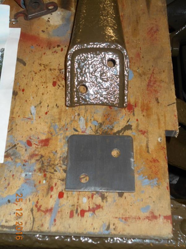
We haven't been idle in spite of evidence to the contrary! Dad has set us the very tight target of London to Brighton in May 2018 when they are having a special WW1 vehicle class. This really is going to be very hard to achieve but we are going to have a go. To that end, I have done a critical path analysis of the project and have realised that the three items most likely to upset the applecart are the bonnet, the fuel tank and the canvas hood of which the longest lead item is the canvas. Jim Clark at Allied Forces has kindly promised to do the canvas for us but to do it in time, he needs the hood frames very soon. I have, therefore, been concentrating on the steelwork whilst Father and our joiner pal Mark, are doing the timber bows. Fortunately, we have done all of this before as the Dennis has hood frames made to the same pattern. Whilst I understand how they go, they are still a very tedious job however! There are two steel pieces on each side, two uprights and two J-shaped horizontal pieces hinged to them. I started off by bending the J-shape using the forge at my local miniature railway. They bent and joggled quite well but when I got them home, I felt that one could just do with a bit of adjustment in my press with the result you see below: It went off with quite bang and just snapped. I was quite surprised about this as it is only mild steel. However, I had heated the parts in a coke fire for an extended period (I am not a good blacksmith!) and then quenched them. The carbon rich environment and quenching had case hardened the steel and caused the breakage. The case hardening is quite evident in the fracture and the edges are razor sharp. I carefully heated and air cooled the second one and then arranged to visit the railway again for another go! In the mean time, I started on the verticals. First task was to turn up some bosses and weld them on. My welding hasn't improved! I did stick them in the vice and lean on them and they remained attached so I deemed them adequate. Then there were two thicker boss areas at the top to carry the pivot point. These were turned and silver soldered on. Then the filing and angle grinding started. This went on and on for hours. Interestingly, the section changes from elliptical just above the pivot to half-round where the timber bow is attached. Careful filing required but they did work out OK. I bent up a second bar and this one went a lot better with fewer hammer marks. It looks a bit odd because of the joggle which is not obvious but which distorts one's perception. Then again endless filing and angle grinding. On these, the pivot boss is generated by filing only. I bolted a washer to the surface to give me a guide. Main pivot point drilled out and the screw holes were countersunk. Pivot pins turned up. Job complete. Now we are waiting for the timber to finish the job. Pleased to see the back of that one! Steve :-)


-
Lovely find! Someone here will undoubtably be able to tell you which company made it. I shall look forward to reading further! Thanks for posting. Steve :-)
-
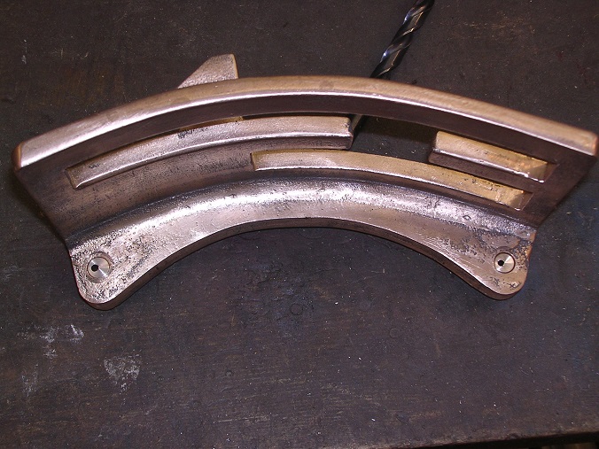
The wheels are held onto the Autocars in a similar fashion. The split collar is screwed onto the end of the axle until the correct end float is attained in the taper roller bearings. The key is then put into the gap in line with a slot in the axle end. On tightening the bolt, the collar grips the axle end and is secured from rotating by the key. Seat Box: This seat box is a copy of the Carlton Colville Thornycroft as close as I can make it. Unfortunately, we didn't have such detailed information for the Dennis so the Dennis one is simply based on it. It is one inch wider (I have that dimension from the coachbuilders' drawing) and the seat hatch is longer to accommodate the fuel tank. The end panel is also a slightly different shape but that was discerned from the photographs. I am sure that the production method would have been very similar to the Thornycroft so this is a pretty good approximation. Steve :-)
-
Now we move to the rear end. There is a compensating mechanism which pulls the RH brake lever directly and the LH via a cross-tube. The compensating link has three pins, previously made by Father. They are ridiculously complicated in that they are cross drilled for oil, have a feather to stop them rotating, a screw thread for a nut and a split pin hole in the end. A simple clevis and split pin would have done the job so I wonder what the reason behind them is. We shall never know. Note installation of the famous Thackery washers! We spent some considerable time getting the lengths right and picking the right pin hole in the clevis. All was well in the end and we have a second functioning control. The final task for the holiday was to drill out a split pin. This stud is pinned into the inlet manifold and has a split pin through the end to secure a bell-crank in the throttle linkage. Unfortunately, we didn't spot the sheared-off pin until the manifold had been fitted making it tricky to remove. I therefore turned up a drilling jig in the shape of a piece of threaded bar with a number of cross holes drilled using my dividing head. I screwed it on until a hole lined up with the pin and then locked it by screwing a bolt in the end. Two minutes with the Dremel and a new drill and the job was done. No drama at all which was very nice. Here we have everything done this week. Two functioning controls, a new seat box and the inlet manifold ready to accept a bell crank. All very satisfying. Sadly, reality is going to bite again very shortly. Happy New Year everyone! Steve:-)


-
Last day of the holiday and we have finished the seat box. The only part left to fit was the flap for gearbox access. The hinges were soon rebated in and screwed down. Complete at last! It remained only to try it out. As I was clearing up, I had a closer look at my drawings and realised that I had done them twenty two years ago! This project is turning into a long one! The two aging desk-jockeys somehow managed to wangle the thing up onto the chassis as there is simply nowhere else to leave it! Dad plans to paint it up there. Next task was to assemble the hand brake mechanism. This started with the handle at the front, now nicely painted by Dad. It is fitted on a key with a locking bolt to secure. However, there is no split in the bottom of the lever so the bolt only sits in a slot to prevent the handle from coming off and cannot make it a tight fit. I don't think this is a good arrangement and it was remedied shortly after the war. All very satisfactory.


-
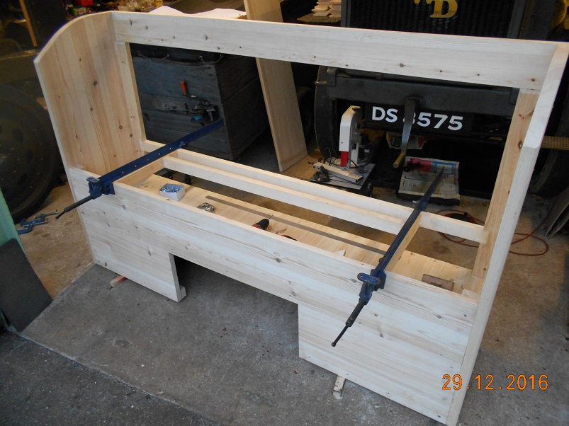
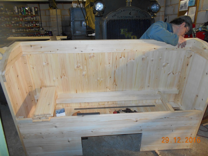
The weather has been OK here although a bit foggy. I'm glad I haven't been on the road. Yes, there will be a canvas covered cushion although it may have had a leather covering originally. I am not sure either way about that and Tim hasn't turned up any firm evidence yet. We have canvas on the Dennis and it doesn't look wrong. No doubt Tim will find something the day after we fit it! We are on the home straight now so I started by fitting the two corner planks of the seat surface. Then the other two and the rearmost piece. The lid was eased very slightly before it dropped in. Another nice piece of Mark's work as it has 'breadboard' ends to keep it flat. And then the hinges. I would not have chosen 'Tee' hinges but they are as the prototype. This little strip runs along the bottom edge of the side panels on each side. I don't know what it does but it is there! Finally, I planed a radius along each inner edge and sanded all of the sharp edges ready for painting. Tomorrow, we shall fit the hinged gearbox access flap which goes in the hole in the front and then the whole lot can be turned over to the painting department. You are right. It is blinking heavy and I don't know quite how Father will handle it! Steve :-)


-
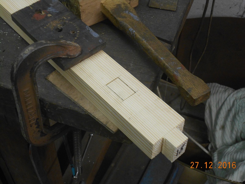
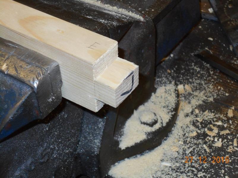
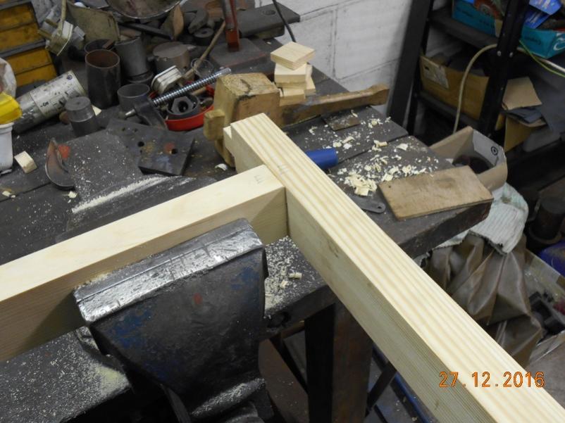
We did a bit more yesterday between guests. First job was to screw the toolbox floor down. Unlike the Dennis which has the fuel tank under the seat, the Thorny just has empty space which is used as a tool box. Most useful! Then it was a case of jointing the rails which run across the back to support the seat surface itself. I knew that lesson I had at school on how to cut a mortice would be useful! Then it was a case of securing the uprights against the side panels, gluing all of the joints and cramping them up. Whilst the glue was going off, I fitted the arm rest pieces inside the side panels. Screwed and glued again, they should stop the side panels cupping. With the cramps removed, we started to panel the rear face. Good old Mark had already cut all the planks to length and left a couple of spares so I only had to plane the last one to width to fit. They were all screwed to the rear with proper slot headed screws. Non of those pozidrive things! We have more guests today but I plan to go outside shortly and make a start on fitting the seat itself. Steve :-)


-
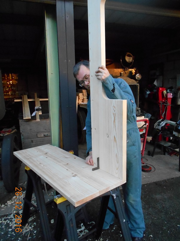
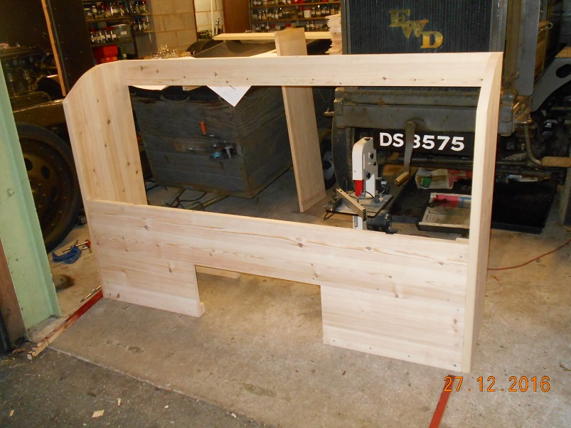
A return to the fray! We have started on the seat box but the first challenge is where to start? I drew the thing 22 years ago and, quite frankly, can't remember how I planned to assemble it! We started by cutting the profile of the top edges of the sides where a doubler is screwed inside. Tim then sanded them to shape. Then it was a case of cutting out some rebates in the side panels fort the front and rear panels. A simple, if somewhat tedious job with a chisel. Success! A pair of seat end panels ready for assembly. The heel panel has ribs along the back to bolt the seat box down and also to support the seat. These were jointed and glued into place. Then assembly could begin! Screws through the end panels hold it all together. These are not visible in any of the photos we have so they will be deeply countersunk and then filled before painting. A cross-rail was added to support the rear of the seat. Tomorrow, in between receiving guests, we plan to add the remainder of the seat support and then glue the whole assembly together. We hope to have the whole lot ready for painting before the return to reality! Steve :-)


-
Well, as the festivities die away, we have made a start. As Dad said, Mark has delivered the timber for the seat box, all beautifully prepared, and I have been eying up the job to see how to approach it. I see that I did the drawings in March 1994 which shows how long this project has been in progress! Then we had a go at fitting the gear lever quadrant. As I mentioned before, the slots did not appear long enough and were too far forward so I filed 3/16" from the end of them and moved the mounting holes forward 1/16". This proved not to be enough but a suggestion that I received here, to shim the change shaft bearing forward was acted upon and I made a 1/8" spacer to go behind the inner bearing. That just tipped us over the edge and the lever fitted the slots just right. Unfortunately, the centring springs now proved to be 1/8" too tall! These were reduced by bending the tips over a bit further in the vice and success was achieved. The gear change is now finally installed and functions quite well. We will press on with the woodwork tomorrow. Steve :-)


-
Hi Barry. The original item was brazed on using a brass alloy. I have used silver solder because I am a lot happier that I can achieve a good joint and, as far as I can make out the strengths are very similar. The only downside for silver solder is the cost! The way the joint is made, there is plenty of contact area so I am quite happy that it will stand up to the use. Thornycroft seem to have used brazed joints in quite a few places including the brakes and drag link so they must have had some confidence in the process! Steve :-)
-
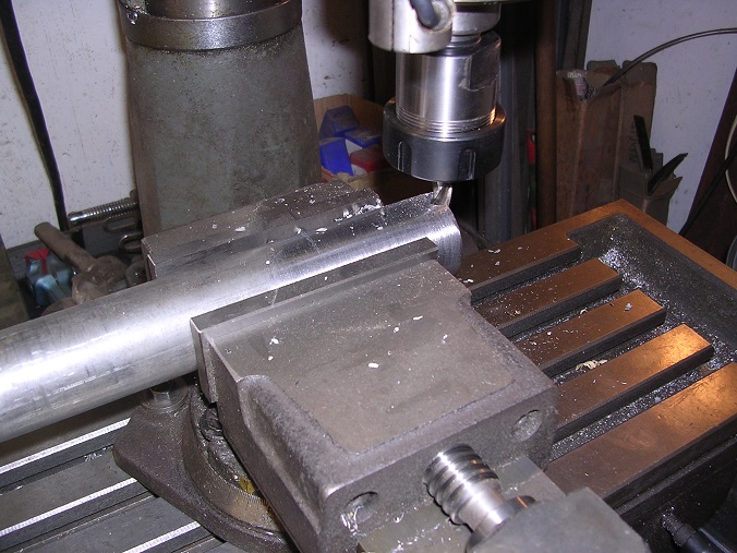
Thanks Andy. That's a thought. The steering column had been sawn off long ago. However, we do have the bottom half of the inner tube. This gave me the section (so I thought) so we bought some 1 1/2" x 1/8" wall steel tube to push over the 1 1/4" worm spigot. I then proceeded to cut the key slot in one side. The steering wheel spigot was then silver-soldered on. The bottom end has a clamp around it to prevent the tube from spreading when torque is applied and to grip the worm spigot. Ours was rusty but serviceable, until I tried to push it over the outside of the tube! What I had thought was corroded 1.5" dia tube actually proved to be 1.458" outside diameter! The simplest cure for that was to skim the outside of the new tube so, once again, the big Dean Smith and Grace lathe at the Echills Wood Railway came into its own. Another slot was cut up the rear face to give the tube some room to squeeze onto the spigot. Another Christmas job is now to cut the outer tube which, I believe, Father has in stock. He is pretty good at this advance planning lark! Steve :-)


-
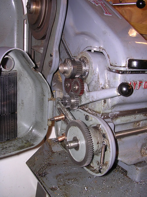
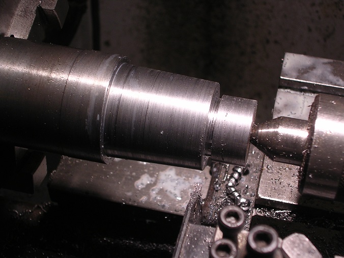
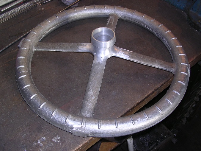
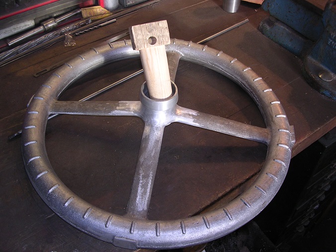
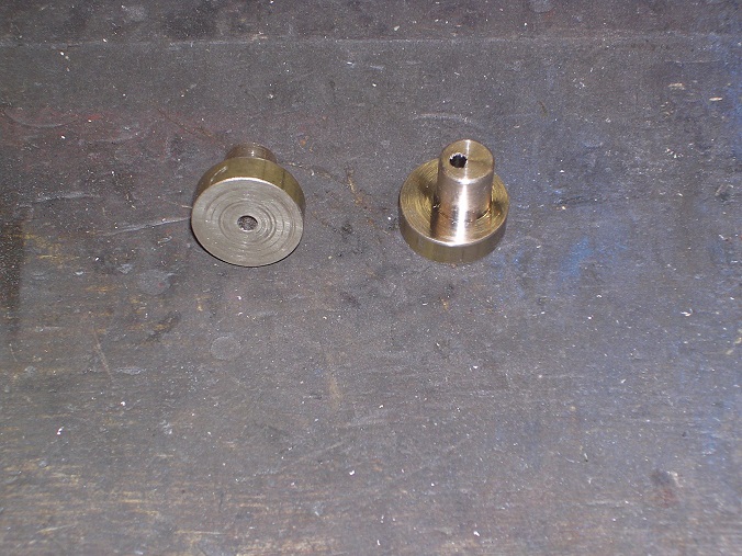
Onto machining the spigot. First job was to bore the end to suit the new steering column tube. Then turn it around and turn a taper to match the original and cut the thread for the nut. The Myford lathe is a wonderful flexible tool. However, to change the pitch of a thread when screwcutting, the gear train driving the leadscrew must be dismantled and the correct ratio gears selected and fitted. One day I will treat myself to a gearbox! The thread was cut using one of the cutters from a coventry die head, supported in a simple holder. Two complete spigots and the original. One for the Maudslay and one for the Thornycroft. Once the spigots were available, I could machine the wheel centres, using them as test pieces. Amazingly, I didn't take any pictures of the process. Suffice to say, they were mounted on the faceplate of Father's Colchester Student and this was the result. I have attacked the edges of the boss with a Dremel pencil grinder and sanding drums to blend them in and the result is quite pleasing. Father has volunteered to finish the job before black powder coating all over. I have turned a plug to the same taper to help the powder coater by being able to thump it into the bore to mask the surface and also give him something to hold on to. On to the column next! Steve :-)


-
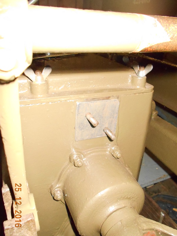
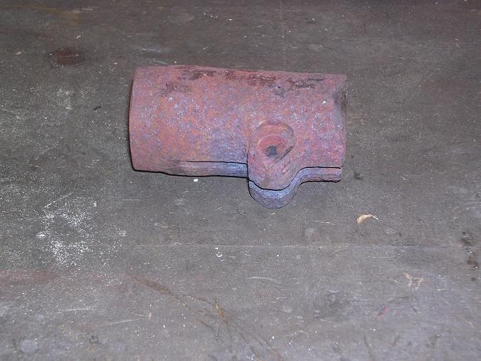
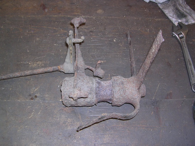
With planning the Christmas blitz and seeing as we have been working in the area of the various controls, our thoughts have turned towards the steering column and wheel. You may remember, from page 113, that we had two steering wheels cast from our pattern so that one could be finished off and fitted to the Coventry Transport Museum Maudslay lorry. This was musch earlier than we needed it so it has been on my living room carpet ever since! First task was to machine the hub of the wheels to suit the column. We had been fortunate to be given the top of a steering column and steering wheel centre from which the dimensions could be determined although, as you can see, they were a bit poorly. I cut through the column between the wheel and the hand throttle to see if I could work out how it went together. To be honest, it was not obvious! Then my pal Adrian kindly sand blasted it and it became a bit clearer. There is a 1 1/2" tube pushed up into the end spigot and brazed. You can see the spigot with a line of rust seperating it from the outer tube which does not rotate and which carries the hand throttle and advance mechanisms. Then you can see another line of rust seperating that from the bottom of the steering wheel itself which forms a shroud over the outside to stop the rain getting in. The spigot has a key into the wheel and a lrge nut on the top to secure it. Interestingly, the sand blasting also revealed that where the column tube had been completely corroded away, only the braze remained to protect the steel. The spigot was removed by use of heat and my hydraulic press. When it finally movved, it went off with quite a bang! From the spigot and photographs, I could work out what the replacement should look like and proceeded to make up the nut t go with it. The second nut is for the Maudslay.


-
We are preparing for the Christmas blitz at the moment so that we can make some progress. One of the things I want to do is to finally fit the handbrake and gear levers. The handbrake requires only a key and some paintwork which Father is doing at the moment. The gear lever, you may recall, did not quite move far enough due to the quadrant limiting its travel. To allow a bit more travel, I have firstly filed another 3/16" from the end of the slot. Then I aimed to win another 1/16" by moving the bolt holes. I wanted to add 1/4" boss on the side anyway so I turned up some brass bosses with the locaing spigot offset. These were successfully silver soldered in but left the gunmetal filthy! After drilling the holes through and spending a good time polishing the casting, this was the result. Hopefully, this will be enough but if not, it has been suggested that I move the shaft centres. The right hand one is fixed but I could shim the one on the gearbox by as much as 1/8". As the selectors at the box end drop downwards and those at the lever end are about the same length but upwards, then the lever should move forward by 1/4" at the quadrant. We shall see! (Thanks for the suggestion David!) Steve :-)


-

Copper and brass parts mainly for electrics
Old Bill replied to Citroman's topic in Pre WW2 vehicles
Thanks for that. Always good to have contacts. Steve -
Progress continues with a few efforts to reduce the number of outstanding patterns needed. Firstly, the fuel tank sump. We will need this before we can start on the tank. Then the magneto advance shaft support. These two will be gunmetal which is why I have done them together. They follow my normal methods of using MDF and car body filler along with some more of the wonderful flexible plywood. I did push its flexibility to the limits this time though! A bit of broom handle turned to make the bearings. This was glued in place as one piece to ensure that the ends remained in line after which the centre was removed and tidied up. A bit of body filler dressed back and it was ready for painting. The sump was an interesting exercise. The ends I turned and bored in the lathe before putting the ring through the bandsaw and joining them with straight bits. Then dress to shape with the sander and glasspaper. This is my first pattern with a loose piece. After painting with Bondaprime and rubbing back with wire wool, I made sure that the loose piece could be removed freely. As you can see, with the split line on the bolting face, the pattern cannot be removed from the sand. I therefore created the loose piece with the locating peg arranged such that the top hat piece can be drawn straight upwards leaving the loose bit behind. That can then be drawn out at 45°. At least, that is the theory! The patterns are now with Dad awaiting the next trip to the foundry. Steve :-)


-
You are quite right in your description. Thornycrofts obviously hadn't got around to updating this part of the engine when they built yours! I have just been looking at your thread again and it is a most interesting project. Have you made any more progress? Replacing the reverse gear pinion shouldn't be too hard as they are only simple straight-cut gears. Ours has a plain bush in it so I expect yours is the same. Good luck with it. I am looking forward to seeing some more pics! Steve :-)
-
Last weekend, I was fortunate to be in Devon again so the first thing to be done was to fit the wick feed oiler that I forgot to take last time! Then it was time for a trial fit of the handbrake lever. This had to be adjusted in the press to get it to run between the quadrants after which I fitted the pawl onto the spindle to work out where it had to go. This was silver soldered on and then polished before installing. Not much room for a spring under there! Next was an assembly of the gear change mechanism. The quadrant had to be packed inboard to allow the lever to centralise. Unfortunately, the neutral position is a bit further back than the quadrant allows so I will have to extend the slots rearward and adjust the central divider. It is all looking promising though!


-
Many thanks for the links. Unfortunately, they all have double coil spring locking washers rather than the Thackery anti-rattle washers so they are shaped to bit in rather than just fill the space. One has some Thackery washers but they are all small and used predominently for carburettors. Thanks for the suggestions though. We will keep looking! Steve :-)
-
That's interesting. Several of the old Thornycroft machine tools ended up with the Hampshire County Council Museums Service and were used in their workshops when I volunteered there years ago. The HSE visited and had a fit which we thought was very unfair. Everything was appropriately guarded. The tools were just very old and were built with a different mindset from today. Oh well. Happy days. Steve
-
Well, the ambulance is a Renault but the one showing battle damage, I am pretty sure, is not as there is no sign of the scuttle mounted radiator. It does look like a big staff car. I shall await some input from the Gurus now! Steve


