


g0ozs
-
Posts
887 -
Joined
-
Last visited
Content Type
Profiles
Forums
Gallery
Blogs
Events
Articles
Store
Downloads
Everything posted by g0ozs
-

restoration Simca Marmon SUMB MH600BS No. 18595
g0ozs replied to g0ozs's topic in Blogs of MV restorations
Now sold (as spares for BNT92K) -
restoration Simca Marmon SUMB V8 No. 17310
g0ozs replied to g0ozs's topic in Blogs of MV restorations
Now on its way to a new home in Devon (along with the other one, for spares). The buyer contacted me as a result of posting on HMVF so I will make a donation ...

-
CVR(T) gets another upgrade, from the ukrane this time
g0ozs replied to teletech's topic in Tracked vehicles
The picture came from an article at: http://www.armyrecognition.com/sofex_2016_official_online_show_daily_news/new_cvrt_reconnaisance_vehicle_upgraded_with_ukrainian_kastet_combat_module_at_sofex_11005165.html - according to the article the CVRT pictured was upgraded in Jordan by KADDB (hence the arabic text on the sign) and the "Kastet" turret is the Ukranian component, being an upgraded version of the remote weapon station fitted to their BMP-1 APCs. If the Kastet turret is also a remote weapon station the operator must be down in the hull - this must be rather cramped in a Scorpion/Scimitar hull ! I would have thought one of the taller 2nd generation vehicles like Stormer would be a better starting point ? Hope this helps Iain -
Welcome here ! Iain
-
question How many Radio Amateurs do we have?
g0ozs replied to fv1609's topic in British Radio Equipment
Seems like the Foden EKA installation manual is listed again: http://www.ebay.co.uk/itm/A-Clansman-Radio-Installation-GS-6x6-Foden-AC-No-63512-/112017026833 Iain 73 de G0OZS -
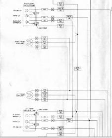
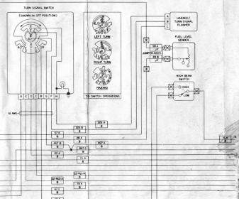
Apologies - finally found a legible diagram for the M997 version online at http://www.kascar.com/Real4WD/manuals/M996-M997-Wiring-Diagrams.pdf - and if yours is similar then the same wires (circuits 22-460 and 22-461 from turn signal switch pins E and C) and bulbs are used for turn signal (T/S) and stop which means that they can't be easily separated. It might be hoped that you could use the separate indicator connections that should be present on the NATO trailer receptacle and use them to control new separate indicator lamps. If it's a standard NATO trailer socket then pins B and J are stop, and pins M and N are separated turn signals. Of course as this is a US vehicle with combined stop and tail lamps, only B and J are connected There are independent indicators (circuits 460 and 461 from turn signal switch pins A and B) at the front end of the vehicle: and I think the least bad options may be to run new wires from them to the back for independent new indicators It may be wise to use LED lamps for the new rear indicators to minimise the additional current in circuits 460 and 461. This leaves the problem of the rear brake and indicators being combined. The brake and indicator unit outputs are combined somehow in the main lamp switch and the input D to the rear indicator part of the turn switch appears to be the brake light control signal. I think the circuits 22-460 and 22-461 are connected to the brake light switch if centred and one side to the appropriate indicator output if the turn signal is in use ? If so I suspect that one side will flash and the other will be on all the time, if brakes and indicator are applied together ? If that is the case, then simply feeding the circuits 22-460 and 22-461 directly from circuit 22 without going through the turn switch should work to get working brake lights with no flashing when the indicators are on. Physically I don't know how easy the back of the turn switch is to get at, if you need to do this. Having written the above, I guess it is only necessary if the indicators will be tested with brakes applied, or vice-versa. I am an electronic engineer (so can read circuit diagrams) but not an auto-electrician - hopefully the above extracts are enough to guide an auto-electrician so that they can avoid either creating a complete new indicator and brake harness or cutting into the original one. Regards Iain

-
Hi Whereabouts are you located ? possibly if someone knows they are nearby they can be of practical help. I believe the wiring diagrams should be available on line if you know the TM number but I would expect that as long as there are separate brake and indicator bulbs behind the red glass it should be possible to connect a separate indicator in parallel with the indicator bulb socket (which will involve cutting into the wiring close to the lamp cluster) and leave the original bulb out. I guess it is to some extent a matter of originality vs practicality whether you fit something like a landrover indicator alongside the original or look for a military light cluster that includes separate indicator and brake light sections. At one time the French used a lot of US-style light clusters but had separate indicators so a search of the Marmon or Hotchkiss Jeep parts dealers may turn up something suitable. Regards Iain
-
question How many Radio Amateurs do we have?
g0ozs replied to fv1609's topic in British Radio Equipment
Andy Thanks. I think I have one of those angled mounts in storage - I will take a photo if I can find it next time I am at the barn (and would be quite happy to donate to the EKA restoration for postage cost if I can find it and John wants it). I note that John reported his EKA antenna mount was at the rear - this diagram shows it above and at the rear of the cab, so I guess there was more than one way to do it. Regards Iain -
question How many Radio Amateurs do we have?
g0ozs replied to fv1609's topic in British Radio Equipment
John Some photos would be helpful working out what was there - also dates when the EKA was in service - I expect it would have been VHF and if it was Clansman (1976-2004) there was a rectangular 14" x 8" base plate the radio would have been a Clansman UK/VRC-353 (4m, 6m and with mods 10M FM @ 50W). This would usually have had a small ATU controller box (ARFAT) about 4" x 6" near the radio and a long 7-pin control cable from the ARFAT to the actual antenna tuner (TUUAM) in a box under the No31 mk 7 antenna base. This is what it looked like: http://www.g0ozs.org/clansman/rt353/photos/RT353FP.html The manual (sort of) is at: http://www.ferret-fv701.co.uk/radio/clansman_vrc353_description.pdf Steve Slack M0SLK has documented the 10M FM mod http://www.clansman-radio.co.uk/353-10m-mod.pdf Regards Iain 73 de G0OZS -
now sold Two videos by Tommy Atkins Media - "the Bren" and "the Sten"
g0ozs replied to g0ozs's topic in HMVF Classifieds
Now sold subject to payment being received. -
now sold Two videos by Tommy Atkins Media - "the Bren" and "the Sten"
g0ozs replied to g0ozs's topic in HMVF Classifieds
PM Sent ! -
Dear all Two videos from my late father's collection - £5 including UK 1st signed for postage each or £8 for the pair Please contact me via PM here if interested. I will be happy to get a price for overseas posting to a specific country if needed. Regards Iain The Bren and other light machine guns The Sten and other Sub-Machine-Guns


-
for sale Firearms books from my late father's collection
g0ozs replied to g0ozs's topic in HMVF Classifieds
Apologies pictures came out a bit wrong - the last one of the sub-machine gun video belongs with a separate listing. -
Dear All I have available the following for £5 each including 1st class signed for postage in the UK - please ask for an overseas postage quote if required. Most are soft cover reprints. Regards Iain Reprint of Lee Enfield rifle handbook English translation of AK47 handbook American origin book on P08 Luger UPDATE 1st June 20:03 - SALE AGREED English translation of P08 Luger handbook UPDATE 1st June 20:03 - SALE AGREED English Translation of Mauser C96 handbook Reprint of original German language Luger manual Book about 1900 US Army Luger trials


-
I used to watch in the days when the MoD seemed to be the props department for Dr. Who - I seem to remember the 2nd episode I ever watched (in 1975 I think) featured both a giant robot and a Scorpion tank in dark bronze green (which, with hindsight, may well have been a model) ! Iain
-
The actual antenna clamp tube is moulded in to the rubber body of the mount - if you look up through the bottom you will find that the inside end of the tube is tapped and the antenna connection (either to a wire for HF radio or to a short flying lead from the cylindrical base adapter with BNC for VHF) was secured by a bolt - there was even a special box spanner for reaching inside to install the bold although an ordinary box spanner or nut driver would do as well. HTH Iain
-
Hi Most of the sources are membership sites of some kind (WS19 group and VMARS primarily). There is a slightly more technical manual on an open web site at: http://www.ferret-fv701.co.uk/radio/clansman_vrc353_description.pdf (all credit to the site owner who is I think a member here) Paragraphs 23-43 describe the controls and connections Hope this helps Iain
-
Andy For what it's worth EMER L802 part 1 (Clansman harness technical description) includes the Larkspur Radio Adapter box (and implicitly the harness connector on the J1 box). The partial pinout given for both the radio harness connector and the J1 connector is: PIN A: MIC + PIN B: MIC - PIN C: IC MIC PIN D: PTT PIN E: REBRO command from Larkspur radio to harnesss PIN G: PHONE - PIN J: IC PHONE PIN K: VCR - to Larkspur radio voltage control relay PIN M: Phone + Hope this helps Iain 73 de G0OZS
-
Andy I think your best chance may be to get the schematics for one of the Larkspur J-Boxes and work it out. There were two versions of the harness A and B - if you have a JD9 box in an AFV then it is an A-Harness. There is a good article on B harness at http://www.remlr.com/wireless/b_veh_1960/3.html but it doesn't include pinouts The WS 19 group archive at http://www.megacycles.co.uk/lark.html has EMERs L772 part 1 (A Harness technical description) and L782 part 1 (B Harness technical description) which are likely what you really need. Hopefully Mr. Suslowitz will notice this topic and be able to advise further. Iain
-
I can't promise good weather next Sunday but I really do need it (doing comms for a marathon at Thorpeness up the coast) ! If you see a FFR Defender 90 with a few extra antennas heading east around 7am that's me Regards Iain
-
Not a B&B but have you caonsidered the Orwell Crossing truck stop or the Travelodge at the A140/A14 junction which has a truck park across the road ? HTH Iain http://www.orwellcrossing.co.uk/ https://www.travelodge.co.uk/hotels/37/Ipswich-Beacon-Hill-hotel http://motorwayservicesonline.co.uk/A14#Beacon_Hill
-
restoration New project - Mk 1 Knocker 6x6
g0ozs replied to ArtistsRifles's topic in Blogs of MV restorations
CB2 and IB2 will also work - the IB3 is really only useful if you have 3 radios (and loses some of the other features of the IB2). Of course if you have no radios it doesn't really matter ! The IB2 can be used directly with the 321 and 353 radios - the 351/2 need an external interface box called an IBHA to convert an audio socket to harness. There is a good set of wiring diagrams for the IB3/CB2 version at http://www.ferret-fv701.co.uk/intercoms_&_radios.htm and a freely downloadable manual at http://traktoria.org/files/radio/clansman/prc320/Clansman%20harness%20manual.pdf Regards Iain PS Neil - I probably have some gold fronted harness boxes you can have (untested) for cost of postage -
Headset connector pin-out: Probably best to connect speaker output to pins D and G, ground to E. The sockets to fit a standard Clansman headphone plug do turn up on e-Bay. Or you could salvage them from an audio box e.g. item 111956680559 You won't need the Pressil box if not using the microphone. Iain

-
introduction New Land Rover Tithonus owner from Bedfordshire
g0ozs replied to aceofhearts's topic in Introductions & Welcomes
Hi Lewis, and welcome ! -
introduction G'day from Ipswich, Australia.
g0ozs replied to pyw304's topic in Introductions & Welcomes
Welcome here, from Ipswich (UK) Iain


