


Old Bill
-
Posts
1,669 -
Joined
-
Last visited
-
Days Won
33
Content Type
Profiles
Forums
Gallery
Blogs
Events
Articles
Store
Downloads
Everything posted by Old Bill
-
Not sure yet but we haven't hit a show-stopper! After brazing up the first end and giving it a clean, it looked OK. A stick and a half went into the joint and didn't come out anywhere so I think it is fine. I didn't get the clean fillet I wanted around the bottom but it will be OK. On to the second joint. First job was to cut it to length after some very careful measuring. I was aiming to make it between size and 1/4" short so that I could add shims if necessary. Too long would be a disaster! Father's trusty bandsaw soon made short work of it. That doesn't half save some graft! Then flux both parts and brick up as before. I found myself a nice stool and, using Father's biggest burner, off we went. Flux just coming up to temperature. Run some 455 grade silver solder. Move the torch around the back to make sure it runs properly. And bingo, a nice sound joint. I did a much better job this time and the solder ran right through. Underneath the ring of flux was a nice fillet. I was very pleased and quite relieved! Each joint used a stick and a half which at £14- a stick means that each joint cost £21- to make. It isn't a cheap process but for one-offs it is very effective. I love the process, as you can tell! Then it was the moment of truth and time to try to install the thing. First job was to insert the leathers and partially insert the bolts. Then it was a two-man lift to get it roughly into position and knock the bolts in to take the weight. Amazingly, it was exactly the right length with no shims required. Access isn't bad but I can't sit like that for very long any more... Dad machined the heads off the bolts and drilled them for split pins ready for me to install. There are only six bolts at each end but it is surprisingly time consuming to fit them properly. Back end done. And on to the front where access was more awkward. All went well, however and we have a prop shaft. When you turn the handle at the front, the differential turns. All we need now are some half-shafts and it will drive. Sadly, I am back at work so that will have to wait for Saturday, One more tick in the box! Steve


-
Well, we are still at it but getting tired now. Only two weeks to go now though so we will keep at it. I am down in Devon again and, as the traffic was reasonable yesterday, I managed to put in another couple of hours and fit the bonnet boards. Never as quick or easy as one would expect but satisfactory in the end including a P-clip to stop the fuel line vibrating. I then set to to fit the differential spider. Again, this was quite time consuming making sure that everything was just right. The spider needed a good clean-up so that Barry's gauge would fit all the way down. Access underneath a lorry isn't too bad but I did end up bit closer to it than I wanted. I also don't bend that well any more when crawling in! Dad had machined the end cover casting some time ago so all it needed was a gasket and felt seal and it was ready to go on. It pushed most of the way on but the threads were a bit gummed with paint and the nuts had to be wound the whole way down with the spanner. Then the centre nut went on. This should have tightened hard against the spider but I was concerned when it didn't but continued to push the spider along the shaft along with the bearing inside. At this point and all morning in fact, the shaft had been lumpy when being turned. However, I kept winding the nut and after another complete turn it tightened up as I would expect and the worm went silky smooth, much to my relief. I jammed a piece of wood under the spider to allow me to put some torque on the spanner and all was well. For that job, I must thank Barry very much for printing the pattern for us and for arranging for the spline to be cut. The next job was to put the handles on the bonnet. Dad has been painting like mad and the signwriter is coming on Monday so the bonnet needs to be on! We bolted the handles on temporarily. Then laid the whole assembly on its back on the floor on an old blanket donated by a friend. It is actually better than those on my bed! The rivet snap was mounted in a vice and used to support the rivets from underneath whilst I knocked them down. Fitted at last! Dad is now in the process of touching up. Many years ago, I saw a set of bonnet catches for sale at a rally so I bought them ready for this day. They are genuine military standard but 1957 rather than 1917. Don't you just love NoS parts? I must make the fittings to hold them to the boards now, a project for this week. Then, the main reason for my visit, the propshaft. I started off by setting up a hearth and cutting a piece of tube to go underneath to stop the main tub falling through when hot, a not-unlikely scenario, I can say from the voice of experience! Steel end polished and fluxed up. I similarly fluxed the inside of the casting. Then propped it on the firebricks with a stepladder behind to which was clamped a piece of timber to keep it in place. I really didn't want a six foot length of red hot steel tube falling on me. Heated all round with the big propane torch and all went well. I could have used a bit more solder but it ran in beautifully and I am sure will be fine. The other end will be tomorrow's first task. Finally, some springs had turned up so I installed them on the footbrake shoes ready for when I get around to setting that system up. That is going to have to be soon if we are to manage our test run next Sunday! Steve


-
Well, it is painting, painting and painting. Dad is pressing on with it and now has the first top coat on the inside and outside of the bonnet. He has also painted some steel for the nuimber plates and primed the 'pyramid nosing' so kindly provided for us by Mark and delivered by David. Many thanks for that chaps. It is exactly what I wanted! I wasn't expecting to be able to get that on but we should now, with a bit of luck. The next kill-or-cure obstacle is to braze up the propshaft, the project for this weekend. Everything is crossed for this one! Steve


-
When you look at the pictures, you realise that there was very little standardisation with the numbering. They are roughly the same size and in similar positions but a lot were applied by anyone nearby who could hold a brush! Some are really classy with beautiful shaded script but others are not even horizontal. Our signwriter commented that the font on the Dennis was not of any standard and the shapes were slightly wrong to the eye. He couldn't resist tidying it up a bit! I have just picked a plain font which, to my eye, doesn't look wrong. I hope Tomo approves as this is one of his specialist areas. Steve
-
Arial Bold, 400 point!
-
Thanks Ben , that is wonderful! Yes, the earlier Q-types had the M4 engine. I think the later ones had the AB4 inlet-over-exhaust type. The chart seems to match what we have so I am pleased that we didn't change it. I don't have any time for messing now and everything has to be right first time. Our test run, which is planned for 29th, won't be more than a mile at most! Thanks or the confirmation! Dad has decided that we must have the signwriting done so he has rung the signwriter. He is coming on Monday so I am now panicking trying to produce some artwork for him including choosing a number. This is what I have laid out this evening: Computers make this a lot easier but I need to be careful to pick a font which doesn't look 'new'. There are a couple of very nice vehicles out there spoiled by the style of the lettering which is a great shame. Steve

-
It could have been made in two pieces but I am pretty sure that it wasn't. Malleable iron sounds more likely as it is a good thin section all over making it easy to produce the white iron stage. Was it a common process at the time? I have never asked the foundry whether they do it and it would be a useful process to keep up my sleeve. They didn't teach us about it at college! Not much visible achieved today although I have primed all of the outstanding parts. I have been laying out the lettering for the signwriter but I need Tim's expertise to pick a suitable number for it. I have also been laying out the petrol tin carriers but there won't be time to get them done before Brighton. Steve
-
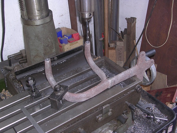
I must admit that I am not convinced either way at the moment. The item has a very definite split line along it which suggests to me that it is either a casting or a drop forging. It was one piece originally although there is a weld repair right in the centre. It drilled like cast iron but I don't know how wrought iron drills. Do you get spiral swarf or chips with wrought iron? It is an unlikely shape for a casting but I also can't see how it would have been forged either. Possibly forge it in two goes at 90° to get the mounting flange and then bend the prongs up as a third operation? Still a bit of a mystery. Steve

-
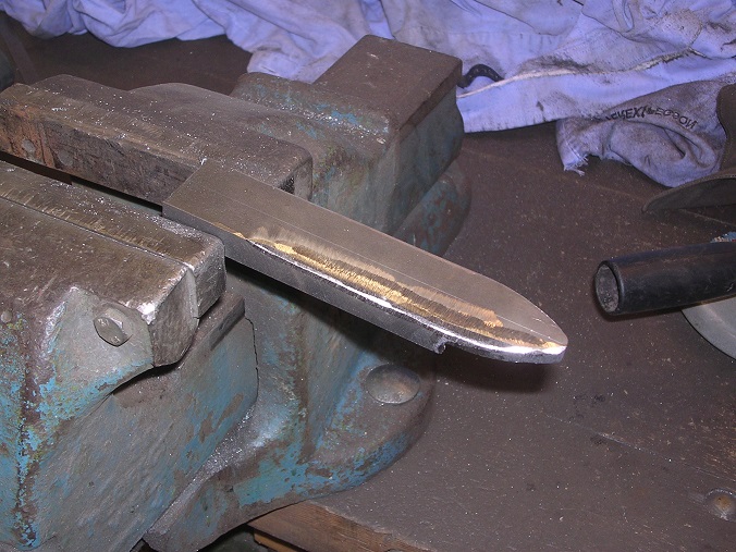
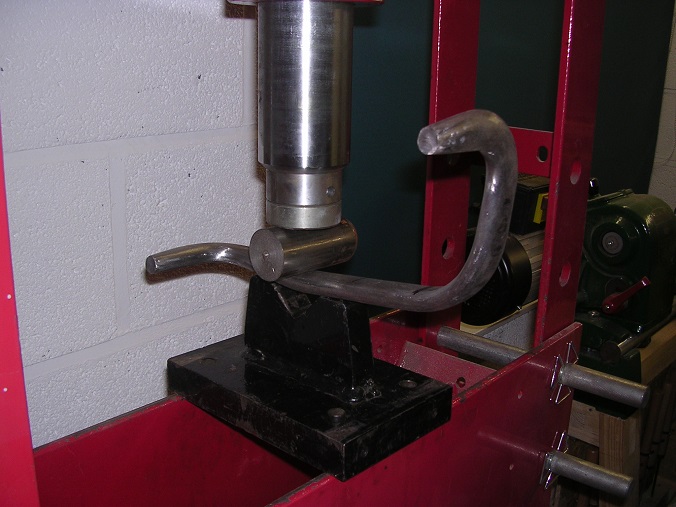
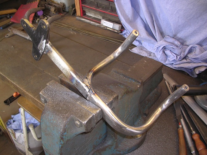
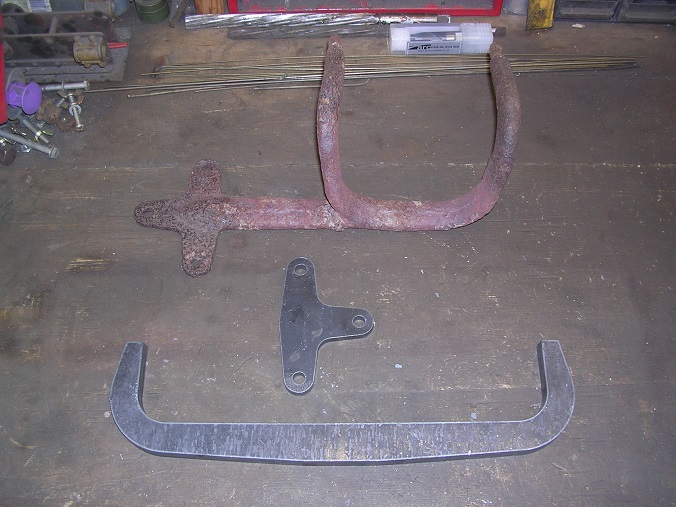
Something else we could manage without are the sidelamp brackets. However, they are very much part of the appearance of the lorry so I have been pushing on wiuth them. We are fortunate to have one original bracket. However, it had been squeezed up to carry an electric lamp and also snapped off and welded at some point.It looks very much like a casting to me although it could be a forging. It is quite sifficult to see how it was made. However, if a casting, I felt that my chances of bedning it back without snapping it were slim. However, I had to have a go. I tried bending it red hot in the vice using an adjustable spammer for leverage. Amazingly, I got away with it. And he second bend. To flatted nt eshank, I put it in the press where I could control the force nicely. Well, that was a bit of luck. I was expecting to ruin it but in the end, it came out OK and I only had to make one more. I had some pices laser cut or, I suspect, plasma cut as the main part is 15mm and quite tapered. It is elliptical in section so a lot of angle grinding and filing later, we had this. I also filed the edges of the back plate and cut the straight piece to go in between. This, I did by hand and then again, filed elliptical. Next challenge was to work out how to bend it. In the end, I put it in the press and bent it cold, a little bit at a time and by eye. It came out OK but the surface suffered a lot of bruising which I had to file out afterwards. The holes were drilled for pegs to be located in the top. The pegs were later silver soldered into position. All set up for welding. My welding is still abysmal! Thank goodness for angle grinders and filler! Whilst the filler was going off, I cut the damaged pegs from the original bracket and drilled for new ones. It drilled like cast iron and I am amazed that I managed to bend it without it snapping. After dressing of the filler and another round of filing and polishing, we have a pair of brackets. Very fortunately, I welded the second to be a mirror image of the first, not a direct copy! Even the pegs are the right distance apart. Into the paint shop tomorrow. Steve


-
We are very glad that you are enjoying it all. We like having you along for the ride as it gives us another incentive to keep at it. This part of the project is getting hard to maintain and it would be very easy to stop without your support so thank you for that. Just on three weeks to go! The progress chart is not doing very well so to help things along, I have moved the final target by taking off evry task we can manage without. That gives us the red line as the final target assuming that we don't fit the tool box, the petrol tin brackets, the shovel bracket and so on. Nothing will be wrong. It is just that some bits won't be there! Too many items will be fitted in the final few days but we should do it. (fingers are crossed at this point....) Anyway, my new drill turned up today so I have drilled and reamed the holes in the differential spider. The reamer, by the way, was a gift from a work colleague which was very kind. However, he had been using it to stir paint so it took some serious cleaning up! Spider is now complete and ticked off the list. Lamp brackets tomorrow. Steve


-
This is all getting a bit 'Monty Python' I feel! WHilst putting the footbrake together, I realised that I had given Dad a wrong dimension and that the pull rod he had made was too short. I have, therefore, made up a slightly longer one. Meanwhile, Dad has picked up the horrible job of cleaning up the bonnet for painting. He tells me that everything is now pink! Hopefully, he will be able to get the first coat of Bondaprime on tomorrow. I have been finishing off the differential spider. First job was to modify the drilling jig so that it would fit over the casting. Then I used the optical centre punch to pick up on the circle that Father had scribed on the back when he turned it. Then just drill through in the mill, one step at a time. The holes are not to size yet as I don't have a reaming size drill for 5/8" dia. There is one on order and I hope to get it tomorrow. Lamp brackets next! Steve


-
Thanks for that Ian. The plugs we have were recommended by Tim Green of The Green Spark Plug Co so we will have to see how they fare. The engine has only run for fifteen minutes altogether so far so it is a bit soon to judge. I will pack a wire brush for the first outing! We didn't stop on Sunday but pressed on with the wing irons. These are proving very time consuming and may only be completed the night before. I don't expect them to be on for the test run so lets pray for a dry day! Started off by welding the bits we made on Saturday. Thes actually came out quite well although I did have to re-weld a couple of them. We then progressed to bending the main rod part. These are 1" diameter and so had to be done hot. Dropped in the hardy hole in the anvil and with a piece of scaffold tube, were soon bent. We did two nose-to-nose to make bending easier. After cutting in two and a bit of dressing, I tacked the first one up. It came out OK so now we need to do the rest, fully weld them and dress them back. I think the dressing back may be omitted for the time being. Meanwhile, Dad has been painting and has primed the footstep and brackets. I am doing a few bits here in Leicester ready for my next trip down south. It is going to be a very close run thing! Steve


-
A million hits? Good heavens! Thanks Chaps! Steve
-
Hi Ben. I was going to ask what flux you used. Is that ordinary EasyFlo flux? As Smiffy says a Tenacity Flux is better for higher temperatures. I use Johnson Matthey Tenacity 4a or HT5 from CuP Alloys. I must say that your piece of steel looks very hot to me. I would suggest that it should only just be starting to glow for a 455 grade silver solder but that may, of course, just be the camera. I am going to have to put our propshaft together in two weeks time the same way. Despite my love of silver solder, I am not looking forward to it! Good luck! Steve
-
So that is what it is called! No wonder I couldn't find it. That is not something I would have guessed! Thanks! Steve
-
Hi Mark. That's wonderful! Thankyou very much indeed. I have been keeping an eye open for the stuff for ages but have not seen it. It is getting these little details right that is so satisfying in a project like this. Newark would have been great but I am still in Devon at the moment. I'll drop you a line shortly if you don't come to an arrangement with David. Sausages we can do! Thanks again, Steve.
-
Well, I started the day by finishing off the footstep and brackets. The brackets were identical last night but that didn't make the step horizontal or parallel to the chassis rails! There was quite a lot of fiddling and messing to do before the assembly was just right. This is what we are aiming to reproduce. As you can see, there are two very distinctive strips of tread plate with square pimples. I have been unable to find any of this. Does anyone know where I could obtain two 23" lengths of this material please? Dad carried on with painting the inside of the body, a job which is very hard on the knees and back! Then we started on the rear wing brackets.These are awkward as I have no drawings and am puzzling them out as we go along. I had had some plasma cut profiles of the mounting flanges cut and spent a lot of time cleaning them up and breaking the corners to make them look right. Then we carried on by propping a rear wing into position. Then Father has cut some steel strips which I curved using the press. Tomorrow I shall weld them up and we will cut the arms themselves. We have had a variety of distractions today but hopefully, will be able to get stuck in tomorrow and get them all done. My last day on the job before returning to reality! Steve


-
That is part of the brake adjustment. The rod has left and right hand threads and can be rotated to take up wear. The weight just stops it rotating in use and gives the driver something to grip to tighten the brakes. I have not seen the idea anywhere else. Steve
-
Glad you are enjoying it. I only wish I knew how the book was going to end as it could still go either way! Another interesting day. It started off with great excitement as the differential spider arrived. Barry very kindly arranged for the spline to be cut by wire erosion and then sent it on. I had to go underneath and see if it would fit and it is perfect. I shall take it back to Leicester and drill the bolt holes ready for my next visit when we plan to fit it and make up the prop shaft. Thanks Barry. We filled the gearbox. Then I noticed the oil level gauge. The aluminium tube which sits on top of the float was right at the top when it was only 3/4 yesterday. This was distinctly concerning so we drained the oil and removed about a gallon of water in the process. Now we are puzzling as to where it has come from. There is no head gasket and we leak tested the blocks before fitting them. The only thing I can think of is that the persistent drip from the top water castings is falling onto the flat top surface of the crank case and then running in underneath the cam followers which are only clamped to the top surface. Hopefully, when we cure the water hose leaks, the problem will go away. Fingers are crossed but it has cost us a sump full of oil at least. On a happier note, I moved onto the footbrake mechanism. I found a spring to use as the pedal return and also cut and threaded the pull rods. The return springs on the shoes are not quite right so I have ordered up some new ones. Once they arrive, I can set it up completely and tick that job off. Finally, we made a start on the footstep. This consists simply of a board bolted to two heavy bent steel brackets. The main puzzle was how to bend them but the trusty press soon made short work of them. I have since trimmed them to length and drilled for bolts. We will put it together tomorrow morning and then Dad can clean up and paint them. After that, we are onto the wing brackets. These are going to be hard as they are bent and welded to look like forgings. Lots of hours there and I only have two days left. We are getting very close to the wire! Steve


-
Thanks Doug. They do look very similar to what I have got so I feel inclined to leave it alone for the time being. It is nice to have confirmation. Steve
-
Hi John. Yes, there is a governor but although the linkage is all there and connected, I did not make a butterfly for it. At least that is one variable we can eliminate! Steve
-
Started the day by making up the pivot pin for the foot brake. Only managed one decent photo though. All the linkage is a pain and the main pedal rod goes through the seat box so will do some more of that tomorrow. This afternoon, we had a visitor and took the opportunity to run the engine again. Using the choke board, it is very easy to start so that is one blessing! It idled nicely but again, just didn't want to accelerate. We had a couple of good bangs and flashes back through the carburettor in the process. As it warmed up, it stiffened and after one of my throttle opening tests, it died. It wasn't so stiff this time although we could hear something tight, so I managed to swing it again for another go. It ran again but eventually died whilst I was messing. Whilst we thought about it some more, David, our guest, had a look at the mag and asked me to advance it. This I did but he saw no movement as we found that one of my joints in the linkage had failed and although I was pushing the lever, nothing was happening. I started it up again and advanced the magneto manually. What a difference! We could now open the throttle and rev the engine. Not sure that we are completely there but it is all looking much more promising. Also, after ten minutes, we switched it off and I tried to turn it again. It was stiff but nothing like as bad as the first time and I could have started it again so that looks promising too. I have just come in after fixing the advance linkage and will concentrate on the brakes and footstep tomorrow. I have also found an oil leak which needs attention. Always something! Steve

-
Thank you very much for that gentlemen. What I have really doesn't look very different from these charts. As you mentioned, Cel, my initial thought was that the inlet was too late but it seems very similar to these. I feel inclined to leave it alone for the moment and have another run first as it has still only started once. After it stiffened up, I couldn't swing it properly again! The stiffening up is a bit odd. I set the ring gaps very carefully according to the instructions on the packet and during the first run, it didn't really get very hot so I would be surprised if it was them. We shall see. Thanks for your help. I'll keep you posted! Steve
-
Many thanks for all of your thoughts. I am pretty sure that I don't need the hot air inlet as modern fuels are so much more volatile. However, I will keep that one up my sleeve for the time being. I have been doing other things today whilst I mull it over but I have investigated the timing and this is what I have found. Taking 'valve opening' or 'closing' as the point at which the tappets contact or part then, at the moment: Inlet opens at TDC Inlet closes 34° after BDC Exhaust opens 32° before BDC Exhaust closes 5° after TDC I don't have a Thornycroft timing chart and my Dennis one is in Leicester. However, these figures don't look right to me at all. The adjustment I have is to move the camshafts by numbers of teeth. The crank pinion has 29 teeth so each tooth represents just over 12°. I should value your advice please. In the meantime, I have connected the throttle pedal to the linkage. This was another puzzle as, although a copy of an original, my pedal seems to be 1 1/2" too long. I have drilled a new hole for the ball joint, a bit closer to the pivot and it all works well. We also assembled the tailboard. The planks are aligned with tongues in the grooves and held together by the bolts in the hinge straps. Dad painted the underside of the hinges and put a single top coat on the planks earlier in the week so that we won't get a line of primer as the planks move with time. Dad then finished up by top-coating the inside whilst I drilled and fitted the foot brake pivot casting. I shall continue with the footbrake mechanism until we have worked out what to do with the camshafts! Steve


-
Hi Chaps. Many thanks for all of your comments and encouragement. I think I have some serious checking of timing and set -up to do. We did swap the crank gear from one crank to the other as it was in much better condition and it could easily be a tooth round. I did work out where I wanted the valves to open and then found that the marks lined up which pleased me at the time. I could be wrong though as it is all a bit difficult to check! I do hope I haven't got to pull the camshafts again but we shall see. Cranking the thing is certainly a feat of strength for which my desk-jockeying is not good training. An impulse starter is in the plan but I just haven't had a chance to do it yet. Oxygen sounds like a good idea. At the moment, I settle for having only a very light breakfast as I don't want to see it twice! The engine stiffening up is curious as it doesn't do that on the other lorries. Barry Weatherhead has reported the same issue with his Hallford lorry. The Thorny has had new pistons, rings and liners which is more than we have done on the others so that may be the issue. I hope it doesn't seize completely on a long run. Lots of food for thought. Now back into the fray! Steve


