Old Bill
-
Posts
1,669 -
Joined
-
Last visited
-
Days Won
33
Content Type
Profiles
Forums
Gallery
Blogs
Events
Articles
Store
Downloads
Everything posted by Old Bill
-
It has been quite an exciting day really.. Tim and I pulled the camshaft out and rotated it through 180° yesterday. Unfortunately, he then had to go home but this morning, we were able to put the engine back together ready for another go. Moving the camshaft had messed up the ignition timing so I adjusted that, primed the cylinders and had a swing. There was a definite 'chuff' but it sounded as if it had blown straight through the exhaust. I checked the timing again and realised that was set to the wrong cylinder so adjusted again and had another go. This time, it fired twice and rotated the engine but did not pick up and run. Now, this lorry has no choke and the instruction in the manual is to hold the float down until it floods and then start. This didn't seem very satisfactory to me so I quickly made up a choke for Father to hold against the inlet. I instructed him to keep the hole in line with the inlet! I had another swing and away it went. Unfortunately, our guest photographer missed the actual start! The film starts a couple of seconds later. We ran for several minutes until it was all beginning to warm up and the exhaust paint cooked itself on. It idled very nicely but as soon as I tried to open the throttle started to die until I released it. I tried this several times until, in the end, it stopped. Now that it was warm, it was too stiff for me to swing so we left it at that for the day and called it a success. I have since stripped the carburettor down to see if there was any dirt in the main jet passages but there was nothing obvious. The jets are the sizes published in the manual so I am puzzled and open to suggestions please. It is a 35mm Solex. Many thanks for all of your kind comments. We are a bit closer to our objectives but not there yet! We will have another go tomorrow when my arm has recovered! Steve

-
Well, it works! We have had some fun and games this morning but eventually, it went and I have some film files to post once I have worked out how to do them.. Idles nicely but dies when I try to open the throttle so I will need some advice about Solex carbs. More later! Steve
-
We are very pleased that you have got something out of it. We only do it for fun after all! Gosh, I ache this morning. Just going out to put it back together and have another go. The question now is will I be able to swing it now that it has the proper compression? I had better go and find out. More later! Steve
-
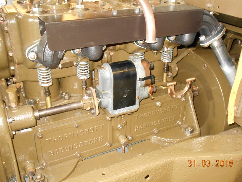
Very many thanks for all of your good wishes. We have had an interesting if not wholly successful day but are all going to sleep very well tonight! First job was to time the magneto. The coupling is interesting in that there is a thread cut around the shaft so that as you turn the pinch bolt, it revolves around it giving infinite adjustment. I set the contacts to open on top dead centre when fully retarded. Then it was time to make up the leads. Feeding them through was an interesting exercise. I had some terminals in stock but cannot decide how they should really be attached. I soldered them in the end using the propane torch. Once wangled through, I connected them up using my meter to identify which is which. They should be colour coded in a specific order but that will be a job for another day, when I remember to bring my coloured tape down. Last job was to fit a return spring on the throttle. Interestingly, I have not seen sign of any return spring on any official photographs and every preserved vehicle is different in layout. Tim got on the hose and filled the cooling system for the first time. This showed a few leaks, particularly under the hose clips and through the studs on the exhaust manifold. The hose clips were tightened or duplicated and more or less solved themselves. The leaking studs we have left to their own devices as I suspect that they will seal themselves up in time. Then it was the moment of truth. Two gallons in the tank and we swung and swung to no effect. The only time it fired was when Ari here put his finger over the priming cock to check compression and it fired giving him a quite noticeable burn! We messed around for ages, priming the pots and checking the timing but to no avail. In the end, we put a rod through the priming cock to check the valve timing against the piston positions and came to the conclusion that I had fitted the exhaust camshaft 180° out of position. We checked this several times always reaching the same conclusion so there was only one thing to do and that was to pull the camshaft. Fortunately, the shaft only had to move forwards enough to disengage the gear so we stripped the front end down and had a look. The marks on the two gears tied up but one whole crankshaft revolution out of position. How annoying! We have moved the shaft up, rotated it through 180° and put it back at which point we packed it in for the day. At least we have found the problem and are well on the way to resolving it. Tomorrow, I shall put the covers back and reassemble the front of the engine and we can have another go. We have had a lot of visitors today, providing extra labour to swing the thing and Tim has been able to be here as well. He has gone back now so I am hoping that it will start tomorrow without too much effort as desk driving is not the best training for this game! Will keep you posted. Steve


-
Thanks Tomo. I'll remember that! We have had a nice day., all bright and still and not cold. I have been pressing on with the hand controls and linkage. First part was to cut the throttle shaft and advance tube to length. Once the tube was to length, I soft soldered the advance lever to one end and the operating lever to the other. The throttle shaft runs up the inside but the tube rattled far too much so I turned up a couple of brass bushes and pressed them in. Trial installation with the levers at the bottom. The actuating collar at the bottom was pinned on and a suitable spring placed between the two collars to keep the actuating levers in contact with the quadrant. Then the hand throttle linkage was made up along with the advance linkage. I still need to connect the pedal and add a return spring. It was all surprisingly time consuming. In the mean time, Father has put two more coats of paint on the wings and Tim has been filling stauffers, a very messy job. Foot throttle, wiring and timing tomorrow and then it is the moment of truth! Steve.


-
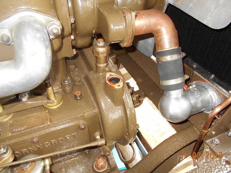
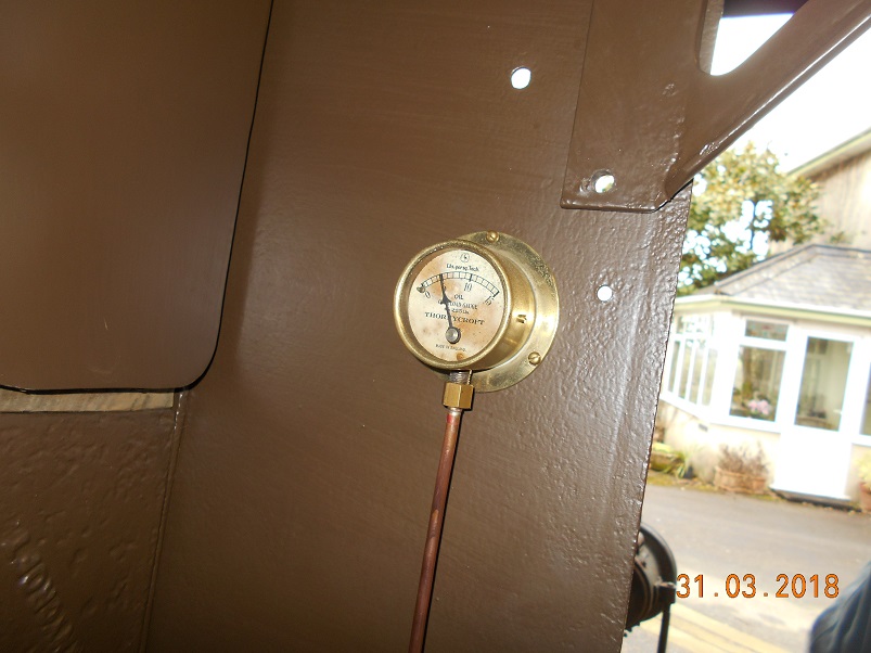
As Dad has mentioned, we are having a bit of a blitz this week with the first priority to get the engine running. First thing we have done is to evict the poor old Autocar from the shed and sheet it over in the drive to give Dad somewhere to work. There is only so much clambering over stuff one can do so we are trying to make it easier to meet the deadline. Once the decks had been cleared, I fitted the oil filler, if only to get it safely out of the way. Once in position, we had to try it out of course. About a gallon and a half later and the float began to indicate, much to our surprise as we expected that it would need engine vibration to move it. I wanted to prime the oil system before we run it so I took the plugs out, disconnected the oil pressure line and swung the handle until I ran out of breath. Well, it is six and a half litres even without the plugs! On the second go, we saw some oil come out of the pipe so I reconnected it. The next swing saw the gauge registering. It is coming to life at last! The next task was to mount the magneto. During my last week off, I made the magneto coupling so all that was needed was the flexi-disc. This is a piece of leather with four holes in it. Our museum friend, Mark who does our leatherwork, found a complete hide of pump leather in a skip some years ago. He rescued it but didn't know what to do with it. This was very fortuitous for us as most of it has found its way into our lorries! Mark used it to make the propshaft couplings and has also given me a piece for general use. As it is over 1/4" thick, it was ideal for the flexi disc. I marked it out with scriber and dividers and cut it with the Stanley knife. The centre hole was taken out with a wad-punch but I don't have a 5/16" wad punch here and wondered what to do about the stud holes. In the end, I used a wood bit run quite fast and that worked out OK> The coupling was assembled and the magneto bolted up from underneath. All was well so I moved onto the advance levers. I had made the levers during my week off so I just needed to cut a shaft to length and pin them on. I have put taper pins through the shaft but looking at the pictures now, what I should have done is put a much larger pin through the block but offset to catch the shaft at the edge of the hole. Oh well. I expect that this will be OK and I shall know for next time. The other end was pinned in the same way. And then final assembly with the location tube pinned between the arms of the casting to stop it moving axially. Throttle linkage and HT leads tomorrow! Steve


-
I don't know what material the roof sheets are. They are extruded as two layers with ribs between and are about 3/4" thick overall. They are a recent installation but the originals did about 30 years before becoming brittle. You couldn't walk on them but they resist our size of hailstones satisfactorily. Dad can tell you more about them. Steve
-
Mark has turned up with some mahogany bars for the longitudinal roof strips and a beautiful piece of ash for the footstep. Dad has continued with the painting and has finished the rope hooks, seen here in undercoat, and has also put the first undercoat on the wings. As always, space is a bit tight! Sadly, I have been at work but I have just sketched out the footstep and wing brackets so I know what we are going to do there when the opportunity arises. Getting a bit close now! Steve


-
Yes, spinning needs lots of practice and I just haven't done enough. I can get the result I want, eventually, but it would be nice if it was easy! Something else we have been doing for a while is the transmission brake lever. Now these come in different versions and we have opted for one with a transverse pull like that on the Portsmouth bus. The Carlton Colville lorry has a vertical pull so you can see that the lever has a bend in it to accommodate this. You can also see the ball joints which I have just made. We started off with another SG iron casting. As the lever rocks, the hole through which the tie bar passes needs to be oval so after drilling, I ran an end mill through it at two angles to generate a slot on one side. Hopefully, this will be enough. The tie bar is secured and adjusted by a wing nut. To stop it rotating and allow for the movement of the lever, the nut has a curved underside with a matching curve in the casting face. I simply created these features with a half-round file. Only the pivot casting remains now to have the bolt holes drilled and then it can all be put together. Something else for Easter! Steve


-
Dad started the day by tapping the pivot pin hole in the brake pivot casting. Rather sensibly, he used the mill to align the tap and keep it upright. Slightly off-line tapped holes can be intensely annoying! There just remain the four holes in the rear face to attach it to the chassis rail. I went back to the throttle linkage. After puzzling over the picture above, I realised that there is a floating link on the hand throttle shaft. This has three holes and is free to rotate on the shaft. The centre hole is pushed by a ball joint from the throttle pedal whilst the outer hole is connected to the carburettor. The link is pushed around by the hand throttle by a peg attached to the shaft. The last photo should make it all clear. In the mean time, I made the floating link in the usual manner. The peg drops from a boss which is pinned to the throttle shaft. It started out as a turning but was then cut and dressed back with a hack saw and files. The peg comes around and pushes it. I hope I have made it thick enough! I have started on the sidelamp bracket too but that's the end of my holiday. Back to reality tomorrow! Steve


-
After doing some more painting, Father started on the footbrake bell-crank mount casting. There isn't actually too much work involved which is the point of a casting. However, the thing is big and very awkward to hold. After a good cleaning up all over, he machined the top face and then drilled it through ready for tapping 5/8" BSW. Next part will be the mounting holes inthe rear face. Meanwhile, I have been working on the hand throttle lever. All my usual approach with a steel profile, silver solderd fabrication and lots of filing. This one has the added interest of a brass knob on the end. The ball turner came into its own again and soon made short work of the job. A bit of Autosol brought it up nicely. Secured with a screw from underneath. I am now part way through the throttle lever at the bottom of the column. Only one day left before reality strikes again! Steve


-
April 2nd if all goes well! Steve
-
Throttle and advance linkage is the current focus and this is what I am trying to replicate. This is the best picture I have and it is causing me a bit of head scratching. That is the bottom of the steering column to the right and just above the spring is the advance lever I have just made. The ball joint at the bottom is attached to the end of the throttle pedal. Whilst I ponder on what I am going to do about this, I decided to make a throttle linkage bell crank. This was done just as the others. Mind you, I think a better photographic background is in order for the future! At least that is one more ticked off. Throttle lever first tomorrow. Then I need to work out how all the bits go at the bottom. Steve.


-
Something I started on a long time ago was the ignition advance lever. We are fortunate in having an original example, albeit broken across the detent. It is actually a gunmetal casting so a fortnight in the pickle brightened it up a bit The original control tube was still in it but rusted off. This was removed by boring it out. The knob was then silver soldered back on and a steel detent made and fitted. The lever has been sitting on the bench for ages and so the time has come to make the actualting arm for the other end. As usual, this started witha silver soldered fabrication (can you see a theme developing here?) Filed to shape using a button for guidance around the ends. Centre hole bored out. This is quite big as the advance mechanism is controlled via tube fitted around the hand throttle rod. Ready to fit. I will cut the tube to length on the job and solder them both on. Another half-done job off my bench! Steve


-
The postman was a welcome visitor this morning as he delivered my ball-ended slot drill. It soon made short work of the buttons and plugs, I have now closed that job down which is great. Steve


-
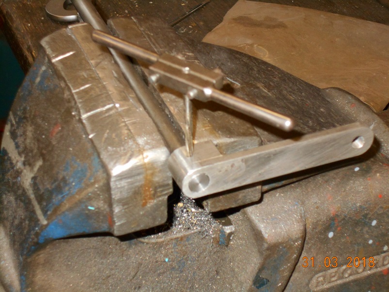
Thanks Andy. Dad has one of these but, as Barry said, it failed within a day! He now has another which he uses regularly. I still do it the hard way but the results are very pleasing. Actually, they laugh at me at work as I often say that I can stand by a vice all day with a file quite happily but five minutes with a piece of software which won't do what I want and I lose it completely! The magneto advance control has two levers on the ends of the shaft so I have made these up this afternoon as well. More silver soldered fabrications of course. This one goes on the end near the bulkhead. I will drill through and pin it in situe. The one on the magneto end had the extra challenge of a bend. Rather brutally, I put it in the vice and hit it until it looked about right. Then drilled it and milled the slot before filing the ends. The slot engages with a pin in the contact breaker and the control shaft is secured by a tube between the two bearings in the bronze casting so I made these as well. I just need another crank on the bottom of the advance control rod and I will be able to put that together. A job for tomorrow. Steve


-
The spinning is a bit hard on the Myford as the forces on the bearings are rather high. I had no option in this case. Even the disc was 7" diameter which is the limit. It got bigger during the process and I had to dress it back with a file to stop it clipping the bed! Have a go at spinning. It is a very useful skill to have up your sleeve. Steve
-
Work still going on apace. Wings are on the critical path and Father has been working on them. I have had the front wings in the loft for 25 years and we dug them out the other day. I orignally painted them before putting them up but it wasn't Bondaprime and the rust has started to come through. Father had top spend a lot of time cleaning them back before painting. David took on the rear wings and degreased them and primed them. Thanks for that David. I need to start thinking about the brackets as they are going to need some significant work in big lumps of steel. They are very heavy bits of ironwork and will need grinding to a curved section to represent the original forgings. In the meantime, I have completed the footbrake bell crank. I started on this some time ago by having a blank cut out by water jet machine. After the centre holes were drilled, it was then machined to thickness in several steps. Then the graft started. This item would have been a forging so the edges would all have been curved. Only way to create that feature was with a file! About four hours of filing later. Then the end holes were drilled out to accept the ball joints currently in work and the main pivot hole was bored and reamed. An additional feature is that both ends are cranked in opposite direction, This was done hot using the vice and an adjustable spanner for leverage. A good wire brushing and another one off the list. Steve


-
I'm sure it could but it would need some fancy tooling to get in there and we are pushed for time now. I'm taking the path of least resistance! Steve
-
Many thanks for that. I hadn't even thought of looking for a pre-cut blank.. I should have put more effort into generating a relief but it would have all been done with the dremel or a whetstone. I'm afraid I have taken the easy way out and ordered a professionally cut tool. I wonder if I will ever use it again? Cheers! Steve
-
I don't hold with this electrickery. Gas lights are good enough for me! The last couple of days, I have been fooling with the foot brake linkage. Rather unusually, it is all connected with ball joints rather than clevises. I am not convinced that this was a good idea but I shall continue with it until proven otherwise. We are fortunate to have one original joint. After stripping down and cleaning, I found that the internal thread is 11/16" x 26. Stupid size! I haven't got one of course so I had to order two taps and a die. Three blanks of 1" bar cut by hand. Oh, for Father's bandsaw! Then on to the plugs. These were a simple turning job before threading 11/16" and then cutting the split pin slots with a slitting saw. After parting off, I started on the balls whilst I decided what to do about the spherical sockets. Then onto the ball sections An Arrand spherical turning attachment. I have only used this once, to make the track rod ends so I had to puzzle a bit over how to set it up. All went well in the end and it was quite a satisfying turning exercise. Cutting the hexes. Now we come onto the spherical sockets. Generating these was a puzzle so I made up a D-bit in silver steel. I could not get it to cut properly until I got it so hot that I softened it at which point I lost patience and went and ordered a ball-ended slot drill. Can anyone offer tips for this sort of D-bit please? there must be a trick to it! More brake linkage tomorrow. Steve


-
I made the slotting attachment to the George Thomas design in the Model Engineer magazine some years ago. It is a wonderful tool and makes keyways very easy and satisfying. The spinning process, I picked up from this book which I obtained from 'Camden Books'. For speeds. the book says 'fast' which isn't very helpful. I tend to run at about 1000rpm which seems to work. The best thing to do is to watch a few Youtube videos on the subject and then just have a go. The book shows the tools so I made them up to the picture. This is the first time I have had a go at beading and, despite some practice, I made a hash of it. Oh well. Practice makes perfect. Just have a go as it is a nice skill to have. Good luck! Steve

-
Dad has been working on the throttle pedal as a back-burner job on and off for a while. He started by turning up the pedal face. Then he hacked out the profile the hard way! He brazed on the bosses and the pivot shaft and the pedal can now be used. However, it should be quite a slender elliptical section which will require a lot of filing. In the name of time saving, he has stopped at this point and we can finish it off later. We are definitely getting into the 'barest minimum' mode now. Nothing is being done wrong (except perhaps the oil fill tube) but we are aiming to do 'just enough'. It is still going to be touch and go though! Steve


-
Hi Doug. You certainly look closely at the pics! Yes, there is a clip on the back of the cup. Not quite sure why but the two fingers would hold the lid vertical whilst filling with oil. I will make one eventually but as the assembly is due for replacement, I am looking for time saving at the moment and will miss it out on this one. Actually, this cup was supposed to be re-used until I messed up the beading! I am pretty sure it should be brass and that the Carlton Colville one is just suffering from extended exposure to the atmosphere. Copper might have been easier to spin though. Steve.
-
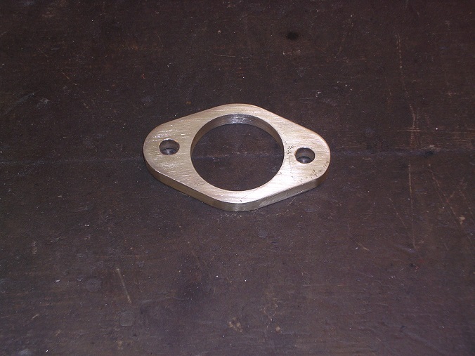
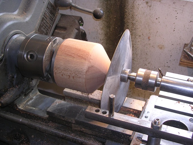
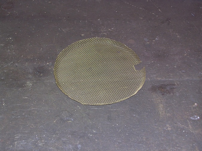
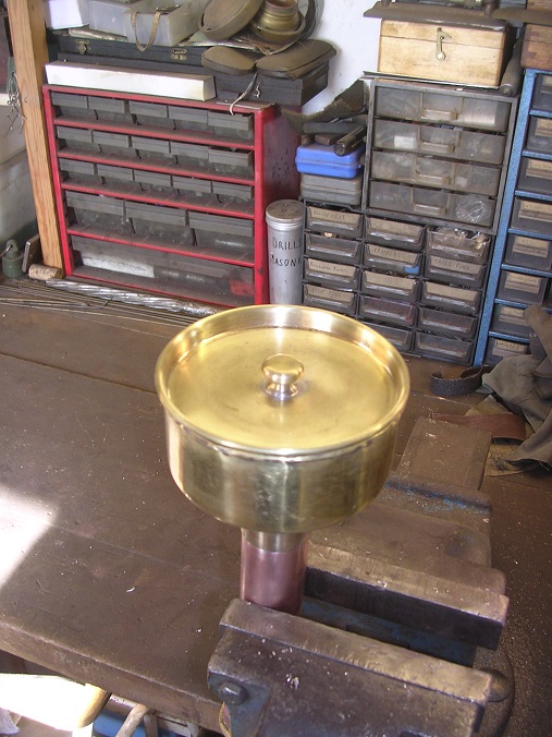
A week off work, Hurrah! I could get used to this. An opportunity to really get things done! I think the reason they all lost the oil filler is that it is copper and brass. Should anyone need Thornycroft information to aid their rebuilds then we are always only too delighted to help. I don't have full engineering drawings of everything we have done but I have an enormous folder of notes an dimensions. That is what comes of nearly 30 years of collecting data! Back to the oil filler. This is what it looks like. As you know, I have been struggling to bend the tube so, for the sake of expediency, I have put together an assembly using commercial fittings. This will be replaced when I find time to make a special pipe bender and can do it properly with no time pressure. I made the base flange a long time ago when I was getting bored with pattern making and desperately needed to cut some metal. The fittings were a gift from a pal in Exeter. Fluxed up for silver soldering. A good clean and job done! Then onto the cup. The only way I could think of producing it was by spinning from a sheet of brass. The first job, therefore, was to turn up a 'chuck'. I found some pieces of old school workbench which I laminated. These were beautiful pieces of beech. Then off we go. A disc of 20swg brass annealed and then rubbed with soap as a lubricant. I am not yet skilled enough to do it without creating ripples or to spin the ripples out. My most successful solution to this problem has been to remove the job and beat the ripples out with a mallet on a piece of wood before having another go. And again! This cup has a beaded top edge which is something I have not done before. Unfortunately, I got a bit carried away and broke the top flange right off. There was just enough metal left to turn over but it is rough and cracked so I will make another when I get around to bending the pipe. It will do. Then spin the lid in the same manner. This time I managed to bead the edge without breaking anything. The lid needed a knob which has a projection underneath to secure a spring. This was a nice turning job. Then the moment of truth, solder the tube to the cup. This actually went surprisingly well but I did treat it with solder paint first, hence the runs which soon cleaned off. The original has a gauze inside to prevent anything from entering the sump. Whilst poking around the workshop this afternoon, I found a shield from the back of an old fan oven, rescued for some reason. It was perfect! A rummage in the spring box found something suitable. Job done! This is only temporary until I can make a better one but it will allow us to run the engine. Start up is going to be the Easter weekend. Back in the shed tomorrow. Foot brake bits next. Steve