


.JPG.ce5d5173b9120e587cf914646a67c75d.JPG)
Pete Ashby
-
Posts
1,681 -
Joined
-
Last visited
-
Days Won
8
Content Type
Profiles
Forums
Gallery
Blogs
Events
Articles
Store
Downloads
Everything posted by Pete Ashby
-
Yep got the scar to prove it Pete
-
.thumb.JPG.fbe532a8a386c5010fe8daa1ff85aa23.JPG)
question Jeep Run Flat inserts question
Pete Ashby replied to Jessie The Jeep's topic in American Vehicles
There is no requirement for the run flat ring provided you are not going to drive 50 miles at full speed on a flat tyre :nut:, they can make getting the tyre off very difficult I have always removed them. The one thing I would say is that they do help to position the valve stem correctly so if you do away with them remember to put a couple of rubber O rings onto the valve stem before reassembly. There will be someone out there who will give you a price for them.......... how much ?? depends on how many punters I suppose :undecided: Pete -
The G503 forum is the place to go. This is an excellent site packed full of detailed information, the trick is to use the correct sub forum and then work the search engine in that forum to narrow down the search. Don't the manufacturers have archives ? the answer to that is yes in part Tony, but they are not so easily accessed as the Chrysler archives particularly from this side of the pond. There are guys on the G503 who have spent a long time trawling production figures and have comprehensive data bases of information. Pete
-
Excellent :D:D:D:D, truth be told it's probably worth more than any metal that's been buried in the dirt for 60 years Pete
-
Yes I used a 2 coat epoxy on my Leyland frame, very good, but you need to work quickly and wash the gun out fully as soon as you'r finished. If your frame is not badly pitted I would go with Richards suggestion of frame black it's easier to work with. Pete
-
:D:D well spotted that man...........should read half a metre :red::red::red: Pete
-
Tools you will need: Cut some wooden wedges (4 or 5 should be enough) they need to be about 5cm wide and 15cm long the angle needs to be around 45 degrees. Next you will need at least two good quality tyre levers around 500cm long. A large hammer A pair of strong boots To to remove the rims: 1 Lay the tyre and rim on the floor, walk around the tyre pushing down as close to the rim as possible this is to start to break the bead, this may take some time. 2 take a lever and hammer and drive the lever at 90 degrees to the rim and at an angle of 45 degrees to the vertical between the tyre and rim do not over do this as the lever will contact the rim base at some stage and may cause damage. 3 Lever down on the lever an at the same time drive a wedge in as far as you can beside the gap you have produced between the rim and tyre wall, now remove the lever. 4 Move to the opposite side of the tyre, ie from 6 o-clock to 12 o-clock opposite the first wedge and repeat step 3. 5 Keep doing this until all your wedges are in. 6 walk round the tyre again jumping up and down on the wall if your lucky the rim will pop off if not cut larger wedges with a 60 degree angle and go round again. If all else fails take it to a tyre shop and get them to do it. DO NOT be tempted to put air into the tyre at any stage even a low pressure can be highly dangerous Pete
-
I wonder just how much coolant you are losing?. To try to pin things down a little more have a think or disregard the following; If you have a leak head to cylinder I would expect to find that you lose coolant in the form of vapour out of the exhaust and pressurise your cooling system. Visible signs can be water constantly blown out of the overflow ( don't get confused by a little as the stat opens and the system comes up to temperature that's normal)or if you remove the rad cap bubbles or a lot of froth in the header tank (this may only be evident after the engine reaches running temperature). Try doing a compression test although in the case of a water jacket/cylinder leak this may not be definitive. You may have a crack in the distributor shaft housing in the block, this is not uncommon and will result in oil dilution without loss of compression however I would not expect to see any vapour from your exhaust as this is independent from the combustion chambers, unless it's extreme and you are sucking vapour out of the sump back into the inlet manifold via the closed breather when the engine comes up to temperature. I don't think this is likely but it ties in with my first question how much and how quickly is your coolant going down. As Richard has already said you may well have a head/gasket/block face/ stud/bolt issue I'm afraid it could be any one, or a combination of these, a compression test may help to narrow this down a little but you may well be down to stripping the head and careful observation for signs of water stain/rust marks and then doing as Richard suggests. Not really a definitive answer I'm afraid, with the type of problem you have it's very much a case of working methodically away from the most obvious and least expensive answer until you find the cause. I would suggest you get a pad and pencil and as you try/examine each option write the findings and results of tests down, you will think you'll remember but you wont and it will save you time and money in the long run. Good luck Pete
-
Looks like it to me Ian Pete
-
Somebody's laughing all the way to the bank then :shocked: Pete
-
The frames come in two sizes depending on use either 20' or 22 ' long by 3' wide all variants have 4' bogie centres. 22' frames are as follows: Workshop, Machinery, GS, Pontoon Search light. 20' frames: Breakdown, Coles crane. If its of use to you I have the sizes for a Pontoon No 5 MK 1 raft unit as follows: 22' long 7' 5" wide 10' 5" high these dimensions will be overall sizes across the the pontoon stations and to the top of the masts. Regards Pete
-
Not easy to tell from the photo but it looks like an overhead valve engine I'd make a pure guess at post war :undecided: Pete
-
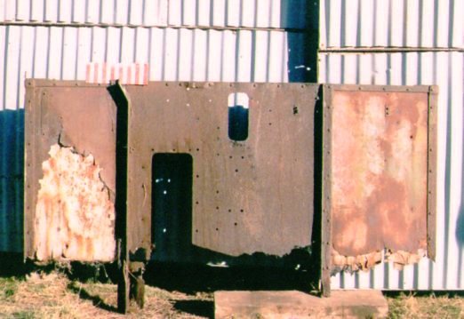
With the frame completed the engine and gearbox rebuilt and installed it was time to turn attention to the cab so it was duly brought out of storage for assessment. It quickly became apparent that the level of decay was far worse than I had anticipated. The Retriever cab in common with other military trucks of the period used a form of cab construction that was common during the inter war years. This consisted of an angle iron frame into which the cab sides and floor boards were slotted this was then joined at the front by the scuttle which in held the whole structure square and rigid. As can be seen in the following pictures there was nothing either square or rigid with the remains of my cab so the decision was made to use the remains of the cab frame and panels as patterns to facilitate new frame work and panels to be fabricated around the original scuttle which was surprisingly in very good condition. In fact the back of the cab fell off as we were moving it into the workshop, so the first job was to build a frame to replicate the main frame rails so that I could work from some datum points and fix the scuttle to the new sub frame and work back from there. I’m afraid these photos are all about decay but they give an idea of what I had to work with. The red and white scale you see in various photos is an aid to supplement measurements and sketches taken of various cab components all of which would need to be re fabricated. As each piece, either wood or steel was removed it was labelled and stored away as a pattern. Here we are looking forward to the drivers’ position and instrument cluster with the rear of the cab and seat box removed This shot is from a similar position as the previous one but gives a feel of the decay in the wood work of the floor boards Here is the back of the cab the construction is interesting as it is made up of two separate panels let into the angle iron frame, one on the mates side and one on the drivers jointed by a sheet of 16 gauge steel in the middle. This is the same rear panel but looking from the front of the cab you can see the rear engine cover in the middle the drivers’ rear seat back on the right This is a close up of the drivers rear panel and it gives an indication of how the cabs on these early war and pre war trucks were put together. There is an outer skin of 18 gauge sheet this has a small lip turned up all the way round then there is a sheet of thin ply wood then a another 18 gauge sheet on the inside with a lip turned the two lips meet exactly in the centre of the ply sheet and all the various bolts………and there are a lot…… hold the sandwich together in the angle iron frame. So for the Retriever cab that’s two rear panels and two side panels joined at the rear by a sheet of 16 gauge steel and then bolted into the angle iron frame which in turn is bolted to the scuttle and the frame……….ho hum not much work there then The next instalment will be a bit more positive as the frame and cab start to come together.


-
Jumping out of second on over run is the more common fault, either way as others had said it's time for a box out and rebuild. Check all shafts, bushes and thrust washers against factory specs and replace if out side tolerance values. The cost of and availability of parts is such now that it's not worth putting worn parts back in. Check all bearings for ware and look carefully at the syncro hub, toggles and blocking rings also the shift rail detent springs and balls. Have a look here http://g503.com/forums/ there are a series of articles with photos that take through a T84 gear box strip and rebuild step by step. Pete
-
Well there you are then Clive, I'm pleased to have given you a warm glow , No Iv'e not seen my old truck either, Neil Randel saw her on the 94 Normandy tour the year after I sold her but no one has seen her since. She went North somewhere in Yorkshire and yes she was a good one, ex French paratroopers with very low mileage and no rust at all complete with an original set of war time canvas. I do miss her sometimes and would love to know where she is now. Well you have jogged the old memory cells with the war on the line convoy, yes I do remember it well they were fun events and always well supported. No I didn't know we made into the D-Day after the battle, I'm not altogether surprised as the shots were very well researched and very accurate as I recall in fact you prompted a massive rummaging through old photos and Iv'e found some which did't make the book but may make you smile...... do you remember getting hit on the helment by a stray ball bearing !!! I'll scan a couple and e-mail them to you, happy days indeed, the world didn't seem so complicated then? now we must stop this trip down memory lane and let Vulture get on with his good work in this thread. best regards Pete
-
question Exhaust manifold leaking gasket advice m38a1
Pete Ashby replied to pockers's topic in American Vehicles
It's me that confused I'm afraid. The penny has dropped, you have the inlet valve in head exhaust in block engine don't you :red: ? Sorry for muddying the water, I thought you had the older up rated side valve. Just do as Ray said in the first place and get the exhaust manifold faced and you'll be good to go with a new gasket. Apologies Pete -
I'm impressed with that.... go out, find a tree chop it down and fit it to your truck :wow: Also really like the saw bench and as a man who burns wood I'm particularly envious of your wood pile :cool2: Pete
-
restoration Dodge command car & Bedford MW
Pete Ashby replied to 44 cargo's topic in Blogs of MV restorations
Very impressed with the dodge scuttle a lot of work there. Pete -
question Exhaust manifold leaking gasket advice m38a1
Pete Ashby replied to pockers's topic in American Vehicles
No not the carb to inlet flange........ the inlet manifold to block face. Both manifold flanges need to be parallel and and in line vertically with the block face. If this is not the case then when you pull up the manifolds the exhaust manifold will be held off the block face by the inlet manifold by the amount you have had machined off. I should say I have assumed that the M38a1 has inlet and exhaust bolted together via a hot spot and that you haven't got a multi branch manifold?. Pete -
question Exhaust manifold leaking gasket advice m38a1
Pete Ashby replied to pockers's topic in American Vehicles
Ray is right, you need to get the exhaust manifold faced but remember you will need to take both inlet and exhaust in together and have them both faced off by the same amount, as Ray points out in his last post an auto engineering workshop will know what needs doing. Pete -
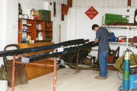
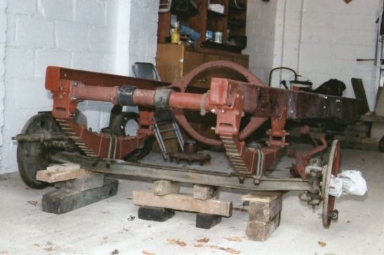
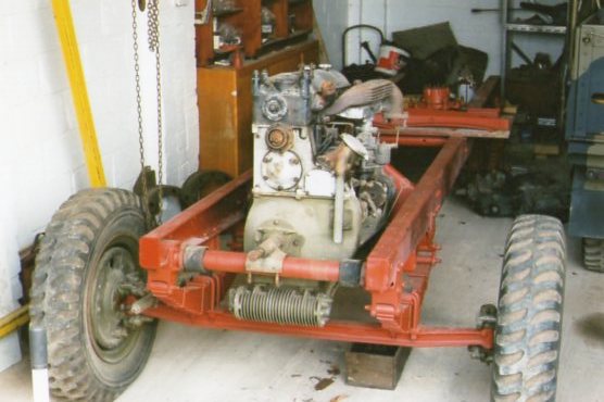
Time moves on to be precise about six years :embarrassed:, The Retriever project was stored away in a thousand labelled tins and pots and the big lumps stored away safe while I restored a 12 cab C15A for a little light relief and then moved workshops across the county, (this involved building a purpose built new one). so the date now is around 2003 and work restarts on the Retriever. Here you can see my son David working on the frame rails they have been cleaned and stripped and treated with a rust inhibitor prior to undercoating with a two pack epoxy frame paint. This provided a very hard surface finish that also filled in any imperfections from rust pitting. this photo shows the frame assembled and under coated and the front axle in position The front springs are on having been disassembled cleaned and painted and the engine has been un-crated and lifted into the frame
-
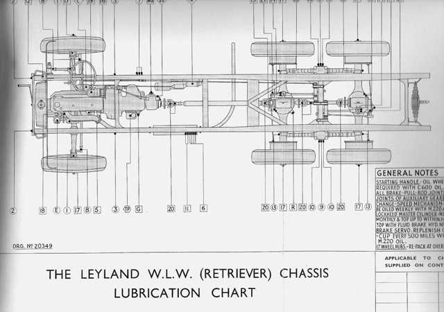
Ok so it's about one year into the project and work starts on taking the frame apart. I don't have too many pictures of this phase that would be of general interest as most are reference photos of greasy lumps of rust for rebuild purposes but here's a couple that set the scene. Before I started to remove any frame fittings I stamped all parts either L for left or R for right, obvious really, but Iv'e learnt the hard way that my memory is not as good as I think it is. Things are not so clear after several years when you go to fit things back on and find that they are handed or only fit on one rail only and it isn't obvious which one :undecided: Getting ready to remove the gearbox and cab supports. This is the handbrake linkage cross shafts to the rear axles............nothing is under engineered, the grease and the quality of build meant that everything came apart and there was very little corrosion damage or ware. Most of the oiling points on the frame are connected via a pipe system so that oiling is carried out at a small number of points on the frame side rail. This is very much in line with commercial practice of the day and indeed was common up until sealed systems became the norm. And this is what you finish up with....a pile of bolts and large lumps here you can see the rear axle case and in front the two frame rails laying on the floor. I thought I'd finish this section off with a copy from the manual of the oiling chart for the Retriever frame. This is reproduced in full on an etched brass sheet that is attached to the mates side of the cab fortunately mine is intact and has cleaned up really well.


-
Thank you Alex yes I do remember the cd that was good few years ago now your model and my truck may end up being finished at the same time regards Pete
-
Found what you want Robert after blowing a huge cloud of dust of my copies of Three on the Floor and getting diverted looking at adverts for jeeps for £200 MoT'd and Doge Command cars for £500 drive away.......those were the days. Right getting diverted again............ here's is the piece you wanted: From T.o.t.F No26 July 1976 Editorial section reported by the late Dale Prior: ' we would imagine that the Ford V8 staff car recently unearthed in Staines South Reservoir will have more than just wiring faults. Dale Prior sent us news of this one (presumably a WOA2) which appeared when the reservoir was drained for the first time since 1943. One cannot help musing how the V8 came to rest in the Staines Reservoir? ' Pete
-
Quite so Old Boy, us Brits have been demonstrating the finer points of our humour to our North European neighbours for 100's of years .........it has to be said mainly as a result of war........... Indeed on two occasions in the last 100 years we have successfully used it as a weapon against your Teutonic neighbours . Regards Chuckles
.thumb.JPG.fbe532a8a386c5010fe8daa1ff85aa23.JPG)


