


fv1609
-
Posts
11,563 -
Joined
-
Days Won
35
Content Type
Profiles
Forums
Gallery
Blogs
Events
Articles
Store
Downloads
Everything posted by fv1609
-
Both circuit breakers are in the box that has the inter-vehicle starting socket. But don't pull it apart until you have confirmed whether your are getting 24v at R & INS.
-
I'm sorry I can't relate to those connections at all. It is a few years since I have been inside one & that was a Mk 1 which is wired & constructed rather differently to the Mk 6. I can only visualise things if you can relate readings to the sleeve identity of each wire. At this stage the most fundamental thing to establish is that there is 24v from: IGN+ (supply to ignition switch) R (with ignition on that feeds into 10A circuit breaker) INS (with ignition on that is the supply from the 10A circuit breaker to the instrument panel) Unless you can get 24v at those key points, there is nothing to be gained at this stage taking readings within the switch itself I'm afraid. Would you like a scan of just the starter & ignition circuit without all the other wiring?
-
Oh crikey I said it was going to be an easy one but I didn't expect to be bowled out straight away. Well done Gordon you are spot on!

-
We all missed you last night Richard. Anyway its not an operating table.
-
To me it points to a problem in the 10A circuit breaker I assume your 24v is at IGN+ then with the ignition switched on you also get 24v at R? R is the ignition switched supply to the 10A circuit breaker. If you are only getting 12.2v on INS, as this is the supply out of the 10A circuit breaker the fault looks to be there.
-
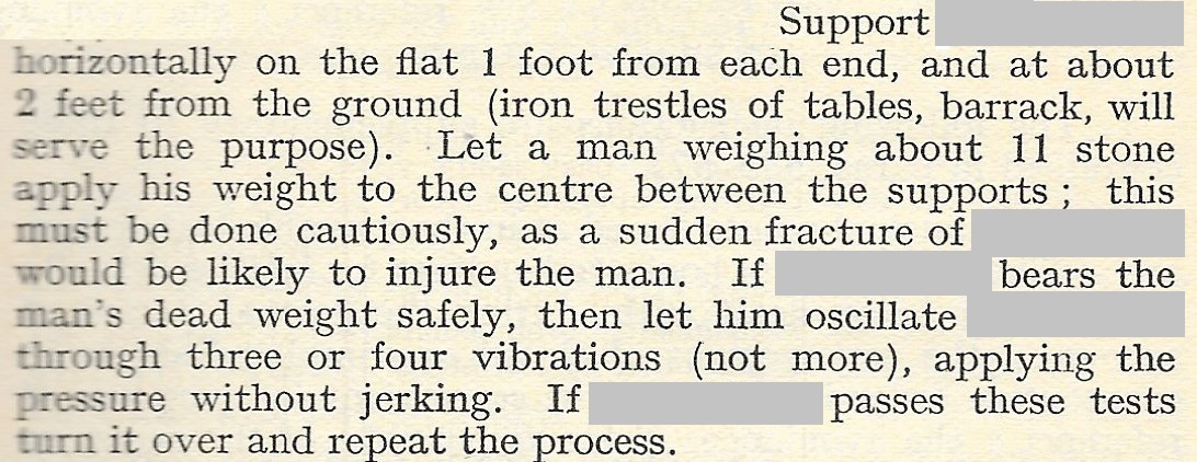
What's being tested here? If it helps this is 1937.
-
Well I thought you deserved an easy one as the last couple were a bit unusual. At least there were no 'peepers' who thought it might be to do with foul drainage I've got another easy one lined up, maybe tonight?
-

question MoT for first time
fv1609 replied to Surveyor's topic in Legislation, Licenses & Registration
I had a vehicle that was unregistered & it needed an MOT before it could be registered. I have the old certificate in front of me just with chassis number. In fact there is a printed annotation "When no registration mark is exhibited on the vehicle the chassis or serial number should be shown." But that was 1988 though. -
I've got a 353 UHB I can do a few pages but not the whole thing.
-

-
Yes well done Derek. Well too easy for the die-hard MO spotters it seems, who nearly all have assembled here. Picture coming up
-
Wally construction correct but it is for keeping water out. Someone has got the answer earlier which I will go & reveal once I can upload the full picture.
-
Good thinking Tony, but its just that it illustrates lifting the thing in two states of assembly.
-
Pretty broad shoulders there Lauren for a coat hanger of those proportions
-
Bernard you academics are really on the ball, I have re-checked you calculations & can confirm you are correct
-
Yes Wally
-
What's this all about?

-
Just make sure you don't have one of these jokers in there! These are all 12A plugs. The lower double female is 12A, but the upper double female is a 30A one. It holds the plugs in by the rubber lips but the electrical contact is unreliable.

-
An earth problem on the instrument panel will have no effect on the starter as that has its own earth. The switchboard starter switch just has to supply 24+ As the panel lights & fuel gauge are dim or intermittent it suggests that they are not receiving 24+ which suggests to me there is a fault in the 10A circuit breaker that is in the distribution box. The thing to do is measure the volts at R & verify it is 24+ then also this is the same on INS. INS is what come out of the circuit breaker. It must be measured under load with the ignition & starter on. At rest there may be some voltage coming through but due to grotty or open contacts the voltage can still pass through the winding that triggers the circuit breaker. But the voltage cannot deliver much current due to the resistance & lights will be dim.
-
Is your Switchboard No.1 still a Mk 1 or has it been upgraded to Mk 6? The Mk 1 switch contacts are relatively crude & the brass contacts erode back making switching unreliable & erratic. The switching on the Mk 6 is of quite a different design & much more robust for the current it carries.
-
Steve if you don't have a circuit diagram it is on page 69 of this: https://www.dropbox.com/s/y7yr2jjujgxuldo/ALL%20CHARGED%20UP%204%20ver4-2.1.pdf?dl=0 With the leads disconnected, to test the continuity of each circuit breaker with an ohmmeter it should read zero ohms on: 30A between AUX+ and B+ 10A between R and INS If they are not making contact at all, either coil winding would have a resistance of 165-191 ohms. If it is less than that there may be some high resistance crud on the contacts.
-
Steve those connectors are rated at 30A I'm not aware of any alternative bullet connector in the civilian market that can fit. Incidentally the smaller ones were originally rated at 10A but increased to 12A, certain types of commercial bullet connectors can fit, but the real thing is not that rare. The distribution box has no fuses, they are circuit breakers that require some sustained overload before they trip. Although when they do trip they do not break the circuit completely as there will be a residual voltage due to the winding still being in circuit. So a tripped or failed breaker may exhibit full voltage on a multimeter but due to the resistance the winding this will drop to very little once some current is drawn by a load. It is sometime since I have taken one apart. The most likely cause for failure is if moisture has got in & caused corrosion, but if it looks clean & doesn't smell charred. I would leave alone for now rather than make work for yourself. I have resistance readings if you want to test it before embarking on a dismantling exercise.
-
Very rare sometimes Colin at BB Engineering has them
-
WW2 British & Commonwealth vehicle restoration colours
fv1609 replied to LarryH57's question in I may be stupid, but......
Looking in MTP. No.46 1939 basic colour KG 3, dark areas DG 4 MTP N0.46 1942 England & N.Europe basic colour SSC 2 or KG 3, the dark areas SCC 1A Was black actually used very much or is that B&W photos just suggest it may have been black? -
Pete that certainly looks an interesting book, although I hope it distinguishes between the types of stores at different depots & sub-depots & not assume all supplied vehicles. Anyway we'll see. I hope some of that detail will be revealed in this, which I was lucky enough to win last night. http://www.ebay.co.uk/itm/British-Army-Ordnance-Regulations-1940-RAOC-RLC-Large-Manual-/371605320171?_trksid=p2047675.l2557&ssPageName=STRK%3AMEBIDX%3AIT&nma=true&si=Sa1zDxUk2K73EWJzAYGtqsX9Z7s%253D&orig_cvip=true&rt=nc


