


g0ozs
-
Posts
887 -
Joined
-
Last visited
Content Type
Profiles
Forums
Gallery
Blogs
Events
Articles
Store
Downloads
Everything posted by g0ozs
-
Jack I know of at least one satcom vehicle with aircon being reconstructed by an amateur in Lincolnshire - if the one you saw had a pedestal and sectional dish beside it, it would likely have been his Regards Iain
-
Jak This is most of the elevation kit for the ground spike antenna used with a 5.4 metre fibre glass mast. There is a metal adapter that fits the GSA base unit to the top of the mast (photo no. 4). The appropriate short coax for the frequency in use (one from photo no. 1 I think) goes from the GSA base unit down to the inductor unit (photo no. 3) that should be clipped to the mast. The normal long GSA coax then connects the bottom of the inductor unit to the radio. The combination of the correct length coax and the inductor unit provides a simulated ground for the GSA to produce the correct radiation pattern and a half decent match to 50 ohm radios. The nylon cord (Photo 2) is used when the GSA is suspended e.g. from a tree rather than on a mast. The key to success is to ensure that the strain relief cords and collars are used correctly and none of the BNC connectors are bearing the weight of the cable and inductor. You can improve the odds by putting a few turns of tape round the mast below the inductor if its springs are tired and weak, so it cant slip down. Inside the inductor unit are about 1/2 dozen turns of thin coax on a ferrite ring - so you can make a more mechanically robust version for a single frequency by using a longer than necessary coax from the GSA base to the radio and coiling up the spare at the same distance as the inductor would be below the antenna for that frequency and then securing the coil to the mast - that way you have two less BNC connections to come loose after the mast is up ! I think (I dont have a set to measure easily to hand) the cables between the GSA base and the inductor unit are 1/4 wave long. If you could measure the ones you have and list the lengths and labelled frequency ranges it would help me with something ! Regards Iain 73 de G0OZS
-
Jak If going the TUUAM/ARFAT route you should really use a No. 31 Mk 7 antenna base with two 1m rods and the cylindrical adapter under the rubber part of the base to completely duplicate the vehicle installation. If using other antennas the EVHF is what would usually have been used with a dismounted 353, or a inverted-vee pointed in the right direction for rear links. The GSA and EKGSA are only usable up to the 15 watt setting but adequate for local use. Power wise note that the 353 needs 3 to 4 amps on receive and up to 12 amps on transmit - the "10 amp" Widney Aish supplies intended for battery chargers tend to shut down when faced with a 353 on full power so you either need the 50A PSU, a vehicle supply, or batteries. I've always used a pair of 12V sealed batteries (ex UPS) in series attached to a LT box to use my 353s in the field as it's quieter and no heavier than a generator and 50A PSU !! At home I use a modern 24V 40A switchmode PSU which is way lighter and quieter than the 50A Clansman unit (and lacks certain disturbing failure modes inherent in all the Thorn PSUs of that vintage!) Regards Iain 73 de G0OZS
-
Rich I will keep working on salvaging the menus. I have had a bit of advice from the webmaster of the page at http://nigelef.tripod.com/fc_computer.htm which has helped me understand it, and eventually (possibly not for a few weeks) I should be able to produce a non-functional simulation of most of it now. What it seems to be is a single board computer emulating the original BATES hosted in a more modern PC which provides access to disk drives and acts as a VDU. I'm not that much further forward with understanding how to use the machine for non-BATES purposes which I actually bought it for however Regards Iain
-
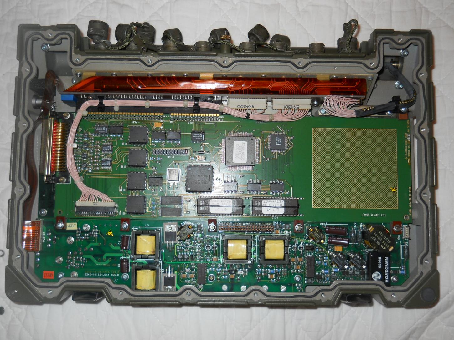
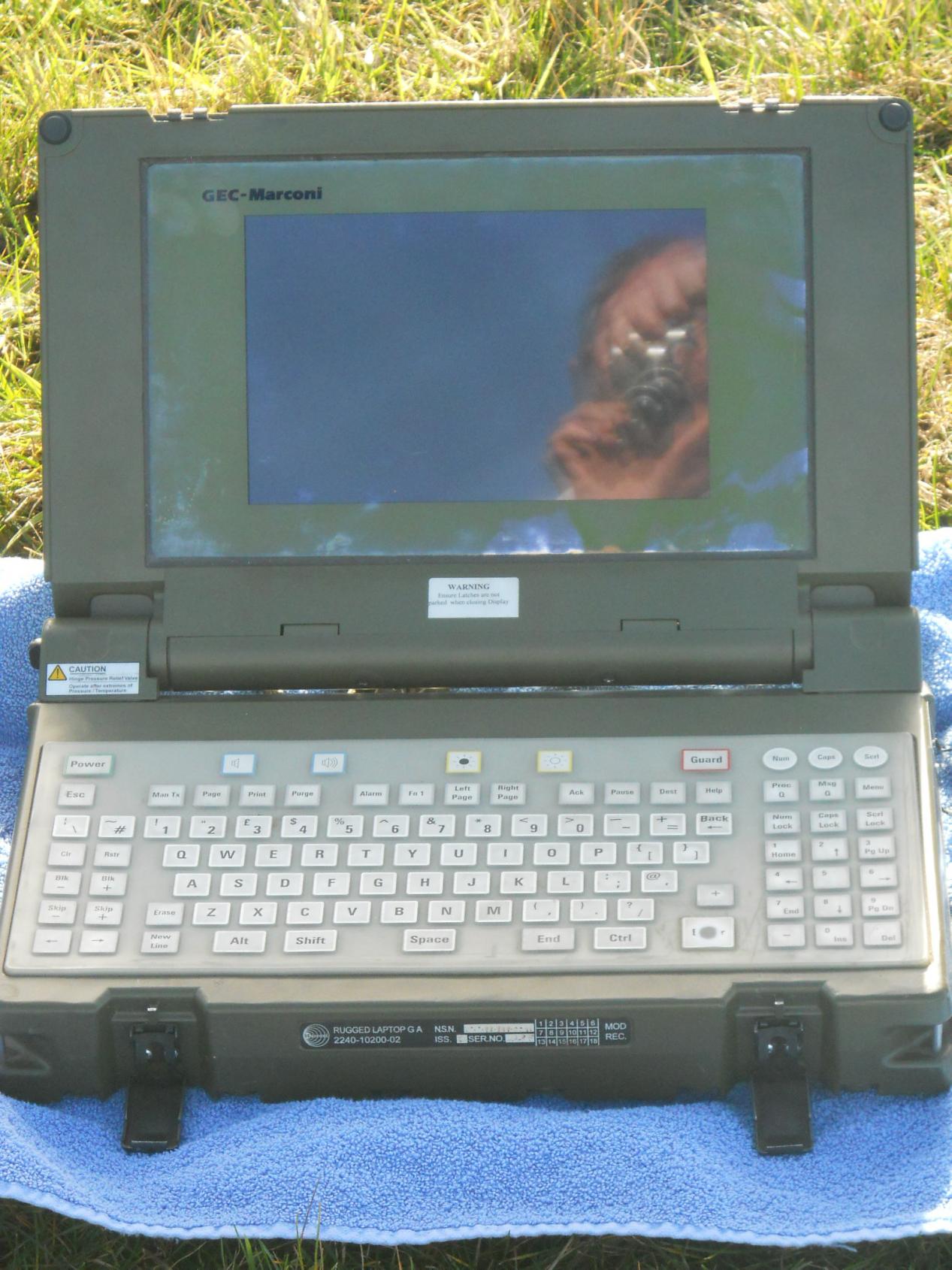
All Here are my GEC-Marconi laptop photos for comparison with the LXI - this is I guess from LACS rather than the FC432 based BATES. Note the custom card above the motherboard in the internal photo. I'd guess that this simulated the custom aspects of the original heavyweight BATES. Does anyone know the pinout of the 7-pin connectors ? They seem to go back to MAXIM MAX211 RS232 level shifter ICs on the custom ISA card which are in turn driven by AMD 85C30 serial communications controllers. The use of the 8530 suggests the ports arent simple RS232 for which the 85C30 is a bit over specified ! The full photo set is at: http://www.g0ozs.org/misc/LACS/ Regards Iain PS in case anyone buys one of these and thinks it is DOA, the power switch is on the right hand side near the SCRL and MENU keys and needs to be fully clockwise, after which you press POWER and GUARD together for at least 2 or 3 seconds to switch it on, when the NUM, CAPS and SCRL will light if all is well. There is no battery but it runs from a normal Clansman style 2 pin power lead.


-
More on the BATES topic than LXI I recently acquired a GEC Marconi Rugged Laptop from e-Bay seller "Advent60" with a corrupt PCMCIA hard disk. I was eventually able to recover some of the contents which turned out to be variants of BATES and BMETS. The e-Bay item was 261385263446 for those who want photos - I'll publish a link to some of my own once I get a chance to do a set in good daylight. The machine has a row of Clansman style sockets along the back (1 power, 6 x 7 pin male, 1 x 7 pin female) which are internally connected to an ISA card carrying a dedicated 80186 CPU and serial I/O chips. The PC motherboard was a 80386LE one with an embedded Datalight ROM-DOS operating system and 8M RAM. Examining comments in the PC code I think most of the dedicated software to interface to BATES peripherals runs on the 80186 ISA card. The machine had no permanent disk drives but there was a PCMCIA 130MB disk occupying both PCMCIA slots on a cover under the left side of the case. I found that the disk was readable by Windows XP and was able to recover it with the Windows XP disk check utility. Hopefully this will give some insight for anyone trying to revive one of these machines. I have had some difficulties photographing the rather dim EL display (if I use lights I get reflection and if I dont I need a 1/3 s exposure so get camera shake). What I have therefore begun to do is to produce a program that will simulate the BATES user interface on a generic DOS PC (actually using the 4DOS environment on FreeDOS to get easy line graphics and cursor positioning, and to make it possible to distribute without licensing issues). So far I have done the main menu and one submenu screen to prove the concept and will make it available as a bootable floppy if there is sufficient interest from reconstructors/re-enactors. Anyone interested please PM me so I can gauge demand. I have pasted below a reconstructed menu screen - it's not perfect because BATES used a different screen mode with more than the 25 rows of a standard DOS screen but I will keep tweeking until it looks better. Regards Iain


-
Andy Thanks for this. Counting the pins I think it is indeed a 60 pin connector (so not SCA SCSI) - can you confirm ? As such it probably has an internal adapter to the 4 pin power and 40 pin data connectors of the IDE disc. Regards Iain
-

Advice needed with Clansman headset connections
g0ozs replied to Hartas's question in I may be stupid, but......
Hi The clansman connections are: Note that this is the fixed socket on the radio - the free cable is mirror imaged looking into it. The Clansman ground (E) and the headphones (D & G) need to be taken by a separate lead to the external headphone or speaker socket on the radio, if there is one (or you can fit one). The 4 pins you have identified can be wired thus 1 Mic Hi = Clansman A 2 PTT input = Clansman F 3 Ground for PTT = Clansman E 4 Mic Lo (ground) = Clansman B Note that the headphones D and G are independent and can be used for different radios (e.g. CB in left and FM Broadcast in right) Regards Iain 73 de G0OZS
-
Mike The TUUAM got power and control signals through the 7 pin cable and the radio frequency input was the BNC coaxial cable. The other end in the back of the FFR went to an ARFAT which is an adapter to use the TUUAM (a RACAL BCC product from the same family as the RT351/2 manpacks) with the much more powerful Marconi RT353. The TUUAM can also be used with a clip-in 351/2 and an Initiate box which just has a "tune" button to be pressed after changing frequency. The TUUAM covers 30 to 76 MHz whereas most variations of CB are between 27 and 28MHz so it would be unwise to use them together. The CB can work with a whip cut to length because of the limited frequency range whereas the military needed the TUUAM (Tuner Unit Automatic Antenna Matching) to cover the much wider military VHF band without changing antennas. I would probably bypass the TUUAM and connect the CB directly to the antenna base and make up a 1/4 wave of Clansman rods cut to length. Note also that the antenna base for the TUUAM would have contained a cylindrical section which contains a transformer that is really part of the TUUAM circuit. The cylindrical section should be removed and the inside of the antenna lead connected to the centre of the antenna base (and the screen grounded as near to the base as possible) in the same manner as for a HF radio, when bypassing the TUUAM. Regards Iain
-
Hello Patrick and welcome in HMVF !
-
Rich I imagine he cant wipe them because he doesn't have a compatible machine ... I expect it will have Windows NT (probably NT4 which is contemporary with Windows 95) and some application software if it is still intact. I assume the BATES application replaced the numeric display and buttons of FACES with something similar on a CRT with a keyboard (the terminal being sold by Melchior 762) but I havent found any screen shots via Google. There is a good article on FACES and BATES at: http://nigelef.tripod.com/fc_computer.htm#FACE (scroll down for BATES, sadly no screen shots). BATES was contemporary with MS-DOS rather than Windows - what you have probably came from LACS the later more portable version. I'll try and post a basic Win95/DOS7 boot floppy on Monday (assuming I find my box of blank ones today!) which should get you a A:\ > prompt. If that works then we can try to reconstruct a BATES screen if anyone has a photo or manual they can share. Regards Iain
-
Rich If I click on the image it comes up about an inch square on my screen I assume the connector is at the end we cant see and the handle on the front would be for extracting it from the slot. The only new info on the ISO group site was the part number "A2N20452723" which however only finds the ISO group listing when tried in Google Before parting with £300 it may be worth trying the floppy boot method - if you want me to post you something PM me the address I should send it to. If you have a screenshot of the original BATES software I can probably try to make it look like that. Regards Iain
-
Mostly military radio equipment here - more the modern stuff like Clansman that can still be used on the air today. (I know a WS No. 19 will work but not many people use AM and I dont trust my morse !)
-
Rich Sounds like the 1st one has either a bad keyboard connector or a fault in the main unit if two keyboards are reported failed by the power on self test. The second one should be more promising if you can get into setup The computer shop guy should be able to help you boot it from CD or floppy even if he hasn't got a hard disk available immediately so you can fully test it. I expect the setup menus may also help him identify the options for the hard disk if it does have to be ordered on line. Regards Iain
-
Rich I'd try the computer shop for the HDD first if only because "sale or return" can be done in real time rather than postal time (although if it uses an 80 pin SCA connector it was probably a server disc rather than a home computer one so will need a shop that has business customers or recycles ex-business servers). The caddy is basically just a frame that adapts the 2.5" disc to the larger slot and ensures that the connector on the disc and the one in the slot are correctly positioned relative to each other so is "just" metalwork to re-create. If the e-bay seller has any decent photos they may help you explain what you are after. The keyboard fault is unfortunate - hopefully the spare will work. If you can get the keyboard working it should be possible to tell it to boot from floppy or CD-ROM rather than the absent HDD - quite possibly that will avoid the need to buy one if all you need is for it to look alive for display purposes. Depending on the BIOS you probably need to press "ESC", "CTRL-ALT-INS" or one of the F-keys to get in setup mode and tell it to use floppy or CD first. If you can do that I can make a boot floopy or bootable CD-ROM for you (PM me to arrange for me to post one, if desired). Do you have any pictures of the screen that you want to reproduce ? What was the e-bay item number for the claimed LXI original disk ? Regards Iain
-
I wouldnt have thought so ! The 322 amp is vacuum tube based but extremely rugged so is very heavy (37KG) and I would have thought the rubber mounts would make matters worse if it ends up with that much metal bouncing around. So I am also puzzled.
-
The 322 HF linear has a wider separation between the mounting bars than the other vehicular radio kit, I think. Regards Iain
-
Robin The 432 looks awfully like the one I saw near Manningtree a couple of years ago - the turret is I think fairly unusual ? http://hmvf.co.uk/forumvb/showthread.php?13807-Spotted-today&p=288972&highlight=manningtree#post288972 Regards Iain
-
Actually military technology often lags what is in civil use by the time it enters service at least in peacetime - the long procurement process and the need for components to be fully qualified to military standards means that what was advanced when ordered is usually available to end users earlier in consumer form and the military generally keep things for long after consumers have moved on - even more so in aerospace applications - so it was quite common to see mid 1970s processors in new military and space designs of the 1980s just because they had an established reliability record and those same designs lasted for 2 or 3 decades in use. I think the LXI is either an early Pentium or late 486 so rather ordinary for a machine used well into this century ! Iain
-
Majorworld The drive connector is some variant of SCA (see http://en.wikipedia.org/wiki/Single_Connector_Attachment ) used for quick replacement SCSI disk drives. I would probably try something like an IBM 90P1300 (Seagate ST973401LC) as a 2.5" SCA disk that is fairly cheap as surplus/salvage and fabricate a caddy if it works. regards Iain
-
Hi WS No. 38 came in infantry (backpack) and AFV variants. WS No. 38 (AFV) was usually fitted alongside WS 19 in armoured vehicles, I think mainly for infantry cooperation. The page at http://churchilltank.com/radio/ shows a typical AFV installation. Hope this helps iain
-
Forgot to add - the small slot with a pushbutton to the right looks like a PCMCIA slot - originally used for memory cards in early PDAs but later also common for crypto cards ( http://en.wikipedia.org/wiki/Fortezza )
-
@Marmite - the connector is smaller than the Clansman one - the parts that fit IARRCS (and hopefully LXI - they certainly look the same on the cyrptomuseum site photo i.e. a mini-clansman for DC and a mini-3pin for AC) are found by searching for DMC Z75 on the Xmod web site. All I have ever said is that these leads fit IARRCS and the connectors on a photo of the LXI to which a link was posted earlier in this thread look the same as the IARRCS ones. I guess we need to wait on the post arriving with Majorweld now to know for sure. @Majorweld - the connector looks familiar - I have seen other commercial SCSI drives with a similar one. I will scour e-Bay and PM you a number if I find one that looks right. But best to wait & see if it powers up before investing, and if all you need is a display booting from a CD or Floppy may be cheaper ! Iain
-
Rich Probably the sensible thing before going too much further is to get a power lead and see if it fires up as far as the BIOS - at that point if there is a screen display and there is a way into the hardware setup screens (it may have been locked out for security/to prevent end users changing anything) you will know if the computer is alive enough to justify the investment in a disc drive. It may even be possible to boot it from a floppy (or if the BIOS is modern enough) a CD. If you need a DOS boot floppy I can probably make one for you as I have some older machines around with DOS. If you just need a display it may be enough to boot from floppy or CD and display a text file that looks like the original application .. Based on the drive bay size it was probably a 2.5 inch IDE or SCSI drive in a sub frame/caddy that fitted the 75mm slot to provide some shock isolation - we would need a photo of the connector inside the drive bay to be certain whether IDE or SCSI although the presence of a SCSI expansion connector on the back of the PC suggests the latter. Regards Iain
-
Majorweld Slight confusion - I don't sell them - look for the NSNs I gave on http://www.thexmod.co.uk - they are about a tenner for each cable before P&P and VAT. I got my IARRCS computer (http://www.thexmod.com/item_detail.asp?id=11991) and cables there a couple of years ago - also minus disks - they have been in storage since my house move but I still hope to revive it when I get time. The cables you need for DC or mains power are http://www.thexmod.com/item_detail.asp?id=12752 and http://www.thexmod.com/item_detail.asp?id=13216 respectively. The IARRCS has the benefit of a floppy drive at least. Someone did get some IARRCS computers with disks that are now on e-bay (item 400272423410 ) at £500 each Regards Iain


