


g0ozs
-
Posts
887 -
Joined
-
Last visited
Content Type
Profiles
Forums
Gallery
Blogs
Events
Articles
Store
Downloads
Everything posted by g0ozs
-

restoration Simca Marmon SUMB MH600BS No. 18595
g0ozs replied to g0ozs's topic in Blogs of MV restorations
Mike Thanks - I will be interested in the mirror holders if (OK let us be optimists - when) you get them back to the UK. I fitted Hymer motor caravan mirrors on my previous SUMB as I appreciated the better vision when driving - the original small SUMB mirrors were only good directly behind. Iain -
Gary Maybe not quite so big is the "loudspeaker gun control" which has a built in battery and transistor power amplifier of the later larkspur era. These use a 600 ohm field telephone input so should be adaptable to a low power source such as the iPod. They are surprisingly loud for what they are but really need a 12V supply (the original battery was a 12V pack in a PP9 9V case). There is one pictured at top right of http://www.g0ozs.org/clansman/G0OZS/DSCN6255.html with the perforated grille. If you had more than one you could probably feed them in parallell. They work well from the remote output of a Clansman set which is how I use mine. There was a series of larger PA systems intended for a battery rather than a single gun under the "Apparatus Loud Speaking" name see: http://hmvf.co.uk/forumvb/showthread.php?10416-Apparatus-Loudspeaking-No-25-for-sale - I dimly remember that No. 23 was a bigger system with several speakers but cant find immediately accessible documentation on line. Regards Iain
-
restoration Simca Marmon SUMB MH600BS No. 18595
g0ozs replied to g0ozs's topic in Blogs of MV restorations
Found a good (if not cheap) new source of the 2 Pin 200A slave/jumpstart connectors to replace the one missing from the new SUMB http://www.hc-cargo.com/default.aspx?id=107&search=Nato%20Plug http://www.hc-cargo.com/default.aspx?id=107&search=Nato%20Socket They are also available via e-Bay as items 111070807509 and 111072349939 which is how I found them - ordered on Sunday and arrived today (Tuesday) very well packed. The actual items are made in China and branded Erich Jaeger GMBH if that helps anyone. -
Jack There is a bit more info at http://www.pyetelecomhistory.org/prodhist/mobiles/mobiles.html#FM900_Series_1983 - the FM1000 is the next generation. They have an EPROM with the channel programming data rather than a microprocessor so you will probably need a prehistoric EPROM programmer to shift them onto a useful frequency. There is an FM900 yahoo group I believe that has manuals for the civil versions - see: https://groups.yahoo.com/neo/groups/FM900/conversations/topics/6770 Regards Iain
-
While waiting for the VMARS membership to go through there is some RT353 technical information at ferret-afv.org/manuals/clansman_vrc353_description.pdf HTH Iain 73 de G0OZS
-
An antenna base ?
-
Very impressive - well done! Iain
-
show report Mid Suffolk Light Railway "Middy at War" 2014
g0ozs replied to g0ozs's topic in The meetings log and photobook
Final Batch


-
show report Mid Suffolk Light Railway "Middy at War" 2014
g0ozs replied to g0ozs's topic in The meetings log and photobook
Third Batch


-
show report Mid Suffolk Light Railway "Middy at War" 2014
g0ozs replied to g0ozs's topic in The meetings log and photobook
2nd batch


-
Here are my photos from today's event - enjoy !


-
Wireless Set No. 38 Mk II - mid to late wartime infantry manpack. A closely related WS No 38 AFV was used in tanks for infantry cooperation - the difference was use of a vehicle power supply rather than batteries. See: http://www.wftw.nl/wireless38-2.html Hope this helps Iain
-
Military vehicle display in suffolk 4th/5th May
g0ozs replied to michael1703's topic in Future events and meetings
A very enjoyable morning it was too. I'll post some snaps in the show report topic later. Thanks to any/all involved in organising the event who may visit the forum! Iain -
restoration Replica T26/vickers 6 ton tank build.
g0ozs replied to mitch's topic in Blogs of MV restorations
Mitch I am looking forward to seeing the finished item out and about - a really ambitious project and going very well so far based on the photos. All the best Iain -
Welcome here ! Iain
-
question Selenium Rectifier Repair/Restoration
g0ozs replied to stivvy's topic in Lubrication, Batteries & Electrics
Chris My understanding of selenium rectifiers is that they do not age well, so even a cosmetically good NOS one may be out of spec. I would go the silicon diode and resistor route, starting with 33 ohms per section (gives just over 10 if three sections are in parallel) and reducing to 10 ohms if the voltage drop is too much, given the ambiguity noted by Clive Iain -
question Selenium Rectifier Repair/Restoration
g0ozs replied to stivvy's topic in Lubrication, Batteries & Electrics
I seem to remember when I started in electronics in the 1970s you could still buy "Selenium Rectifier Substitutes" comprising a large silicon diode and a series resistor - so you could probably make a replacement that way with a modern bridge rectifier and wire wound resistor of a few ohms - the challenge will be calculating the resistor to give the same voltage drop on full load as the Selenium rectifier did, without a working selenium rectifier to measure. See http://w3hwj.com/index_files/RBSelenium2.pdf for a write up on doing it for low current radio applications. Hope this helps Iain -
Military vehicle display in suffolk 4th/5th May
g0ozs replied to michael1703's topic in Future events and meetings
Now in the diary - hopefully we will get there on the Monday Iain -
question Clansman Installation in a Saracen APC
g0ozs replied to Starfire's topic in British Radio Equipment
Looking at the diagram the basic ring topology is correct - if you end up fitting radios as well as intercom their harness ports (or the IBHA harness port) are connected to the IB2 interface box. -
question Clansman Installation in a Saracen APC
g0ozs replied to Starfire's topic in British Radio Equipment
Replying just so you know someone is reading ! I'm not an expert on AFV Harness installations - much more comfortable with standalone and landrover-style ones, so don't feel qualified unfortunately. There are people around here and in the ham radio community (look at the Vintage & Military ARS and the clansman_larkspur and WS No. 19 Yahoo groups) who have got most of it working and between them have collected most of the documentation. Hopefully someone from there is also here and can help, otherwise it will do no harm to join. Regards Iain -
restoration Simca Marmon SUMB MH600BS No. 18595
g0ozs replied to g0ozs's topic in Blogs of MV restorations
Mike Thanks. I've had stuff from rf-parts for radio purposes before but I didnt realise he sold vehicle bits ! This looks more like the switch in the original circuit diagram in MAT3437 with 8 terminals than my one I need to extract the one in mine which has a lot more terminals and figure out which ones do what I need - I really only want it to control side/head lights and tail lights (I don't plan to replace the IR or convoy lights and I don't think I should let the indicators and brake lights be possible to switch off as is the case with the original SUMB wiring). I will probably end up using a relay to actually switch the head lights as 12V operation implies double current and I have a 12V 30A relay somewhere. Regards Iain
-
restoration Simca Marmon SUMB MH600BS No. 18595
g0ozs replied to g0ozs's topic in Blogs of MV restorations
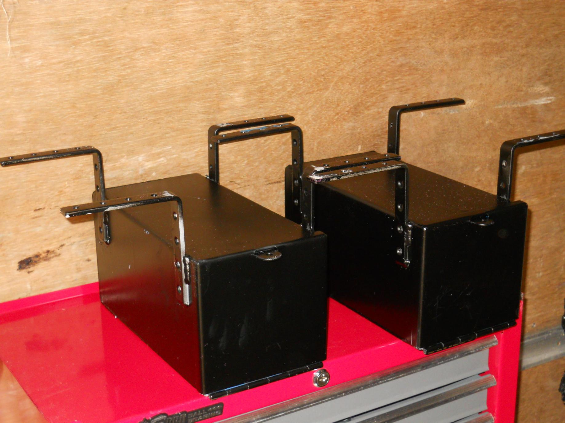
Replacement tool boxes that go behind the rear wheels - thanks to Dave at AWD services for the welding !
-
restoration Simca Marmon SUMB MH600BS No. 18595
g0ozs replied to g0ozs's topic in Blogs of MV restorations
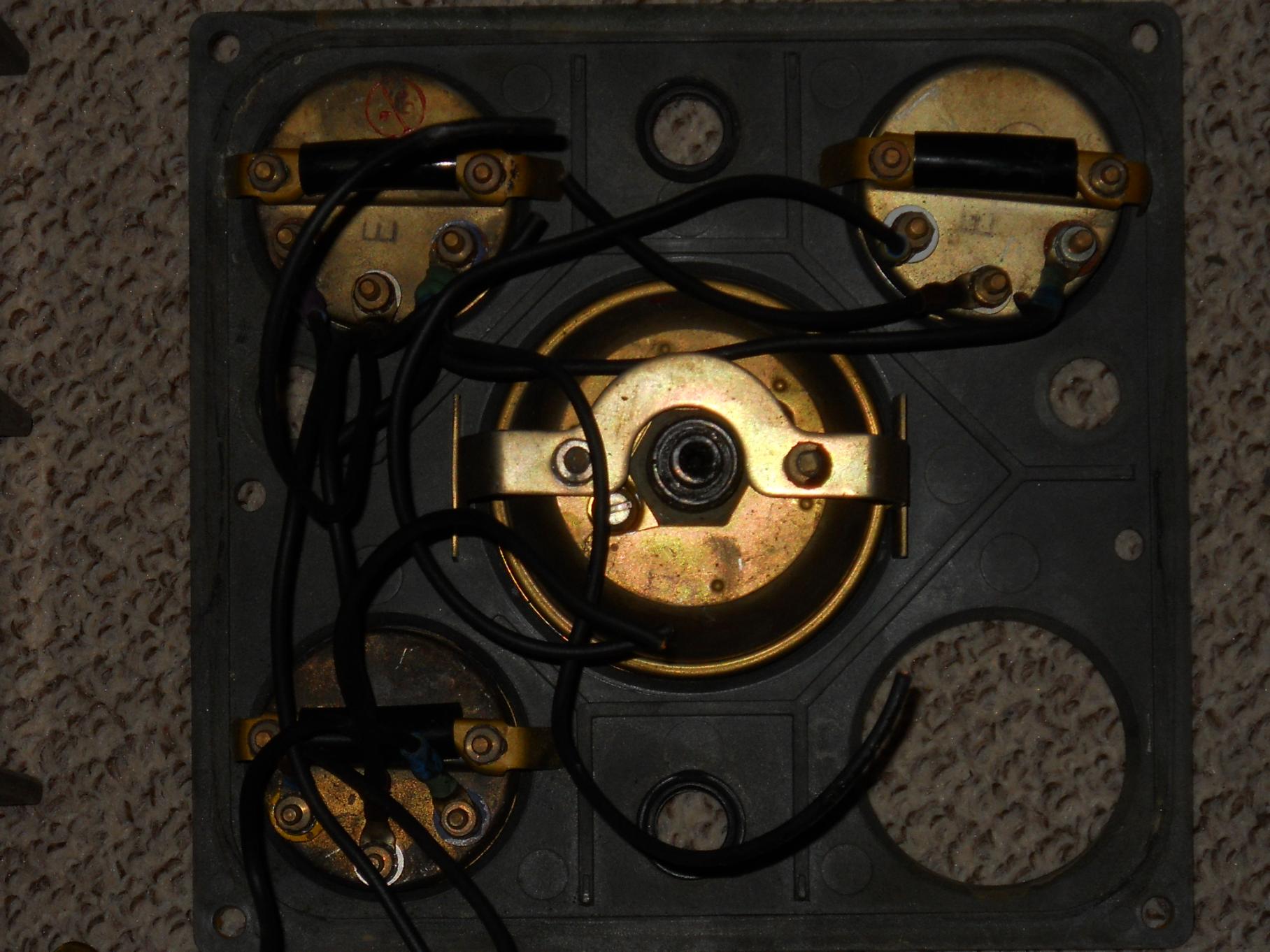
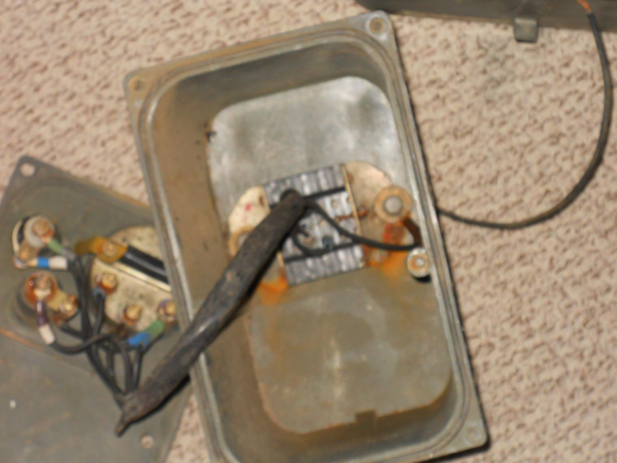
Made a start on stripping and rewiring the control boxes - because the harness plugs were left loose and got dirty and corroded I'm going to have to change them as well as change the lamps for 12V versions. As of now the speedometer box is stripped and I'm hoping to finish the air pressure and main switch boxes later today. Hopefully I can salvage the main light switch but I have durite replacements for the others which dont feel right. Air Pressure Box Main dial box - already stripped - ammeter out ready to fit voltmenter main switch box Inside the main switch box Under the main switch box - anyone know what these connectors are called ? I'm unable to find a source and they are all different pin layouts anyway so I plan on using modern molexes Back of instrument panel Inside the air pressure box - plenty of room for the new flasher switch and unit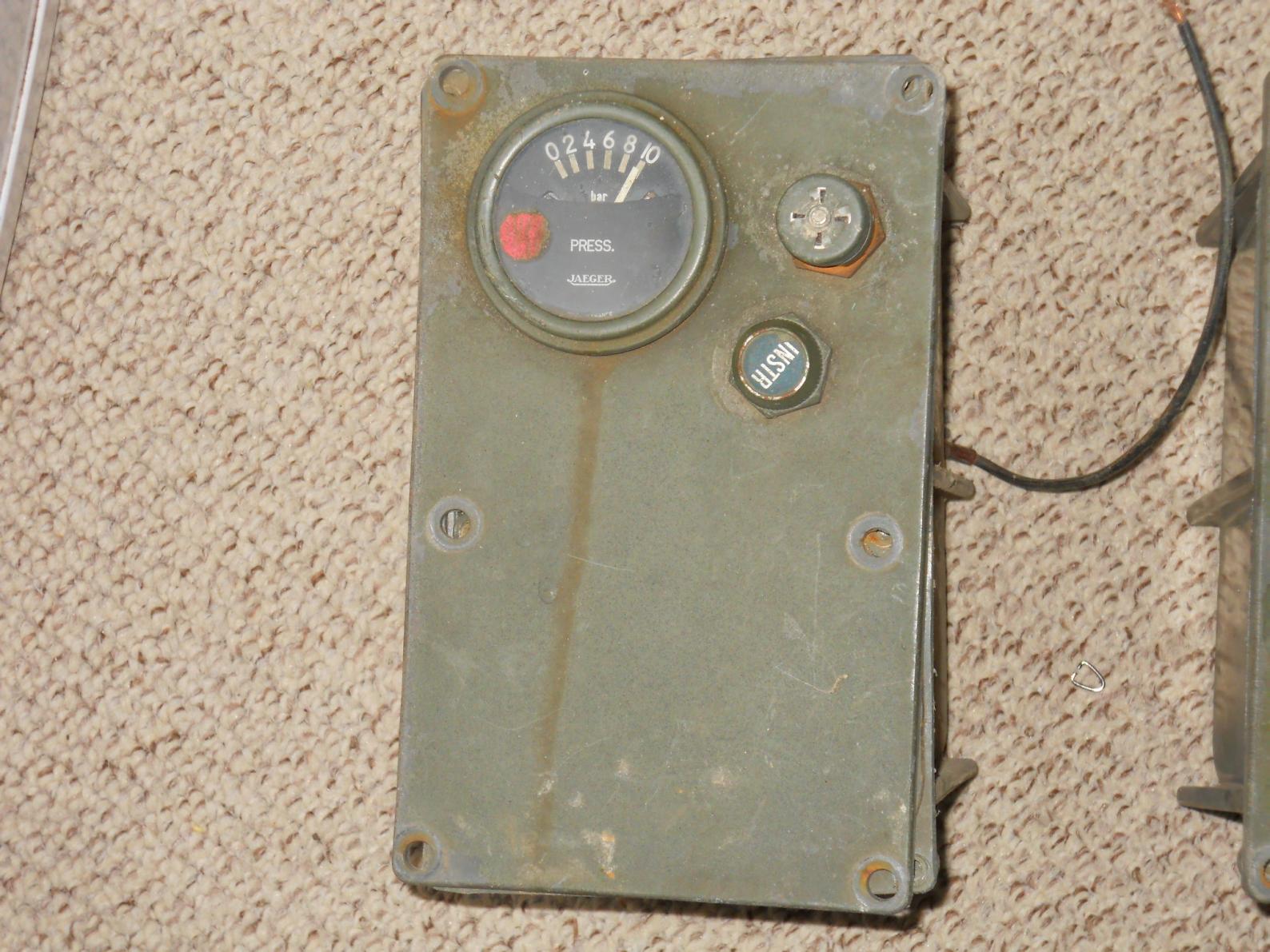


-
PTS Norfolk (seller gten98 on e-Bay) used to have refurb kits including spare knobs - probably worth asking if they have any left. Iain
-
question Top speed for 1944 Ford LAAT F60
g0ozs replied to POPPY's question in I may be stupid, but......
Mark I guess it depends on gearing as well but my petrol V8 SUMB with a little bit bigger Ford flathead (4.2 vs 3.9 litres I think) and about the same weight (3.5 tonnes unladen) could quite happily get to 50mph on the flat, so 30 sounds a little underpowered. Iain


