


Old Bill
-
Posts
1,669 -
Joined
-
Last visited
-
Days Won
33
Content Type
Profiles
Forums
Gallery
Blogs
Events
Articles
Store
Downloads
Posts posted by Old Bill
-
-
We are still doing something in spite of eating too much!
The engine is mounted on two pieces of steel angle which Father has already made. Whilst the RH one is bolted to the inside face of the subframe, the LH one pivots on a spigot bolted to the subframe to prevent the crankcase from having torsional loads imposed on it. We were fortunate in that the spigot survived on the shepherd's hut chassis but unfortunate in that it was completely exposed to the weather for many years, leaving it in a pretty rough state.


We felt that it could probably be salvaged by skimming the surface back and replacing the thread on the end so this we determined to do. The first step was to produce a datum so it was clamped down to the bed of the mill and the two spot-faces were cleaned up.


Two spacing collars were then turned up with careful attention paid to their thickness to keep the spigot true. The whole forging was bolted to the faceplate and 'clocked' into position using the only bit of uncorroded surface left.


After removing 3/16" from the diameter, the threaded portion was removed and a hole bored in the end to locate the replacement.

A short length of thread was turned up and screw cut nearly to size.

This is shown before the final clean up using a proper 1" BSW die to produce the thread form.


After cleaning and facing, the stub of thread was silver soldered into the end of the spigot.


The grease groove was then dressed in using the Dremel pencil grinder.

Tomorrow, we will add the split pin hole and Father can paint it ready for fitting.

Readers may be concerned about the strength of a silver soldered joint securing such a large nut. To be honest, we don't know why the nut is there because the two steel angles are between the subframe rails and bolted to the crank case. With no nut there at all, there is no way that the angle can move along the spigot. The nut only stops the angle from falling off whilst the engine is lowered in and is purely cosmetic in service. We think we will get away with it!
Happy Christmas everybody!
Steve
-
Yes, I understand. It wasn't too tight so I kept going but I was prepared to brace it if did tighten up. The stub is a pretty hefty forging as I found when trying to remove the ball joints. I can only just lift the thing with one hand! We hope to have it fitted by this time next week.
Steve
-
Not much although the plywood packer gave up and I had to find a piece of steel to finish it off.
Thanks for the offer Andy. I have a ball turning attachment for the Myford which I bought to do the Dennis ball joints. In the end, we found enough good ones to do the job so it has never been used. I am looking forward to having a go when the steel turns up!
Steve
-
Thanks for the video Barry. Nice to see it done. I have only read about it and make my patterns to suit. Fortunately, it seems that the moulder reads the same books!
Steve
-
Steve, where was the split line on this part and did the moulder have to do any fettling to make it work?
Barry.
Hi Barry.
I have drawn a red line along the split line for the mould:

The pattern would have been placed face down on the mould board and the sand packed around. After turning it over, the moulder would have cut the sand manually to follow this line and then filled the top half of the box. The split line of the boxes would be a straight line along the flat surface of the pattern and touching at the sharp corner on the LHS. For just two castings this is quite acceptable. For a lot, he would want a backing piece to fill this space and support the pattern during the first ram up. On turning over, it could be taken out and leave the voids which our moulder cut manually. The moulder is a very skilled man and can make good castings from the most unpromising of patterns. I do try to keep him happy though so that when a tricky one comes along, he is more inclined to intervene to make a good casting!
Steve
-
Over the Thanksgiving weekend, we decided to fit the newly machined and painted transmission brake drum in order check that the brake shoe pattern was correct and get the drum out of the way! After a scrape and polish of the spline, it went on with a few good thumps and a block of wood.

It is secured with a single nut which is itself locked with a spring clip which wraps around the outside and engages in a cross hole in the shaft and nut.

I marked the hole positions using a marker and, ignoring the drip of paint which seemed to have found its way into almost the right position, tightened the nut with a socket.

The pin was inserted successfully after switching the nut with the one from the other end of the shaft to get the holes to align....

Finally, the brake shoe pattern was held against the pivot shaft and the drum just to check that it was the correct length before sending it off to the foundry.
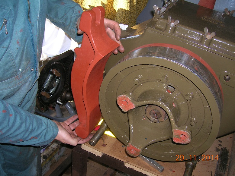
All was well, fortunately!
-
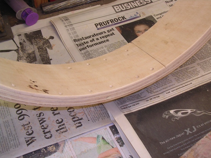
You have already seen the results of this pattern! However, there is some interest. A little while back, we were talking about how we were going to make the pattern for the rear brake drums as it is quite a size. Our joiner friend, Mark, offered to do the donkey work for us by using a laser cut ply ring with several layers of flexible ply for the drum itself. We didn't know you could laser cut plywood without burning it and the flexible ply was a revelation too. I gave him some dimensions and this is what he came up with, complete with draft.

It was a lovely job, made exactly to my measurements and perfectly round which is something I couldn't achieve. I then set about finishing it off, firstly by adding leather fillets.


At this point I realised that I had been very mean with the iron and if it did not come out perfectly round and true, I would not have enough to machine it back. I therefore set about thickening it up using an additional layer of this miraculous plywood.

It bent around remarkably easily and I secured it with PVA glue and all of my toolmaker's clamps. This was insufficient so I also added a further 34 woodscrews to hold it! This worked well and I simply planed the edges back and then removed the screws and filled the holes.


Two coats of Bondaprime and off to the foundry with the results you have seen.
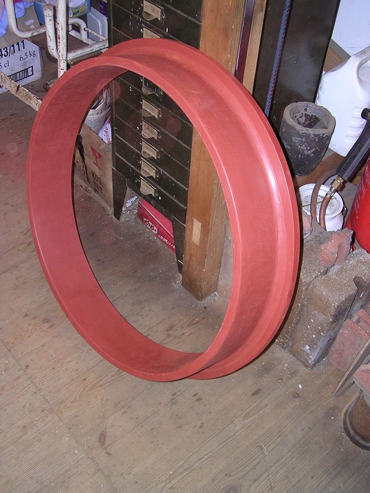
They are remarkably heavy and the foundryman surprised Dad by carrying both at once to the car. Neither of us could do that!
Father has been to the foundry again today with the transmission brake shoe patterns so we should see those before Christmas too. We are going to have plenty to keep us amused over the break!
Steve
-
When embarking on the restoration of your Thornycroft 'J' type this may be of interest !!. From 'General Routing Orders Mechanical Transport' - December 1915.
Richard Peskett.
Thanks Richard. Most useful, if a little worrying!
Steve
-
How do you roll dove-tails into a band?
Barry.
With special dove-tailed rollers of course! :???
Seriously though, do you think it might be a two-part process where the grooves are rolled first and then the ridges given a squeeze which spreads them out at the top?
Steve
-
Just for a change, a little bit of brasswork.
A while back, we were very kindly given a super fuel filter, not quite the right one but one which would do the job with no work and look presentable. However a couple of weeks ago, Tim found this on Ebay:

Comparing it with the parts book, it is exactly the right one although a bit ropey so we decided that it must be brought back and fitted.

Sorry about the awful pictures. I wasn't having a good day. First step was simply to strip it down to find it full of muck and corrosion, as expected. I pickled the gauze in sulphuric acid to dissolve off the corrosion and then straightened it gently using a small screwdriver and my fingers. Someone had unscrewed the filter previously with a pair of pliers and had crushed the bowl. They had also drilled out one end and tapped it for a tap.

I started with the bowl and, after annealing it, held it over a bit of bar in the vice and then tapped it with a hammer and chunk of steel to push the dents out.

Not perfect but an improvement.

Then I turned up a threaded spigot with the correct thread on the end and screwed it in with Loctite. I could have silver soldered it but the suction pipe is only soft soldered into the cap and I didn't want to disturb it.


Finally, I turned up some new union nuts and nipples.


A quick polish and it has gone into store ready for when we need it.

-
So, 2 tons per square inch on a 14" ram sounds like 300 tons. That's a fair bit more than I would have guessed.
We didn't actually get to the limit of the gauge. At least, I don't think we did. It was on the shelf in the workshop! However, there are two pumps of different diameters and each has two pivot positions. To get the first pair of tyres to let go, we were on low ratio of the small pump and it was as much as one man could push on the handle so I think we were well up. Mind you, the lorry was broken up in 1937 and the tyres had been worn out before then so they can't have been moved for at least 80 years. Once they went, it was relatively straightforward to keep pushing.
Steve
-
That is an interesting point... i.e. how big does it need to be... Suppose I was desperate and had to make one. What pressure do you think is required?
The ram is 14" diameter and the pressure gauge is dual calibrated in cwt/in² and Ton/in² up to 2 tons! We used all of it to get the rear tyres started as Tim will tell you shortly.
Steve
-
Another good tip. Thanks John!
Steve
-
The bronze bushes are fully floating in the wheel and on the axle, both front and rear. This was part of the subvention scheme specification so that they would be interchangeable between manufacturers. The Dennis is actually running on at least one Thornycroft bush as it had least wear!
Thanks for the tip, Ted. I will keep that one in mind.
Steve
-
Welcome Adrian!
Don't be shy to join in. Consider that we are in a bar just chatting about the things we love. Everyone has something interesting to add and there is always something to be learned. The only difference is that so many of my friends are a long way away. Half way around the world in some cases!
Come in and enjoy it!
Steve

-
True. A bigger lathe would have made life a lot easier. However, the joy of this game is 'This is the equipment I have got. How am I going to do it?'. There is great satisfaction in overcoming these challenges!
Steve
-
Thanks Andy. You are very kind. It is always good to have another string to the bow!
Steve :-)
-
Mug restoration.
Thanks Arjan. I will remember that for next time. The bits are landfill somewhere by now......
Steve
-
You are going to want one of these for machining the inner radius:
https://picasaweb.google.com/lh/photo/lorjlRbUi9B2VQy0Cd0KcNMTjNZETYmyPJy0liipFm0?feat=directlink
(already used for the same job on Jez)
Unfortunately, I don't have ready access to a borer but my friend Adrian does have this large lathe. I must go and speak nicely with him........
Steve
-
Hi Barry.
My intention is that the split line is along the concave surface. In other words, the moulder puts it on his board face down as shown in the penultimate picture, fills the box and then reverses it so that the concave surface faces up. he will cut the sand away down to the top of the clevis area before filling the top half of the box. The clevis is tapered slightly as is the rib down the back to allow it to be drawn. That is how my mind is working but the moulder might have a fit when he sees it! We shall see.
Sadly, I dropped the Dennis Eagle mug last week so it is no more. It is also irreplaceable as we have a new logo. Very sad!
The acid is sulphuric acid from an old battery. I use it for pickling components before and after silver soldering to remove the flux. It has been there ten years now and is turning into a copper sulphate solution. It needs replacing but these 'sealed for life' batteries are making it hard to do!
Steve :-)
-
Absolutely wonderful! Looking forward to seeing some more soon!
Well done!
Steve :thumbsup:
-
Exciting stuff! Well done!
What is the story of that one? Is it a modern one or hundred years old?
Looking forward to seeing it in due course!
Steve :-)
-
Another way of boring wheels (if a lathe is not available) is to put them on a radial drill. I did this with a tractor wheel a few years ago, with a homemade tool holder.
Marcel
The nice thing about this hobby is working out how to achieve something using the equipment at your disposal. That one is quite impressive!
Steve :-D
-
I think we might notice an inch eccentricity, even at our speeds!
Steve :-D


WW1 Thornycroft restoration
in Pre WW2 vehicles
Posted
We have had a leisurely afternoon fitting the sump to the engine. First job was to give it a final clean using a nylon brush in the pistol drill:
The oil filter suction tube was fed in from the end and secured.
Then the oil level indicator and float was fitted. The float sits in the oil and supports a thin aluminium tube in a gunmetal housing. These were repaired many moons ago and have been in storage awaiting this moment. It was nice just to have them ready to fit.
We treated the sump with a bead of modern silicone gasket and then held it up and nipped up the nuts.
Tomorrow's task is to fit the cover over the timing case and then the oil pump.