


Old Bill
-
Posts
1,669 -
Joined
-
Last visited
-
Days Won
33
Content Type
Profiles
Forums
Gallery
Blogs
Events
Articles
Store
Downloads
Posts posted by Old Bill
-
-
Yes, I can see now that this one has a heavy cloth (Hessian?) or a mesh backing. I wonder how they got the letters so straight and neat as there is not the faintest sign of a wobble. I hadn't thought of using pins but even they will be difficult in small letters. Other plates have a textured background of dimples or pyramids. Was some sort of laminate available at the time which could be glued onto the pattern backboard?
Thanks for your comments. An intriguing puzzle!
Steve :-)
-
Glad you are learning from the discussions. There is so much knowledge out there and it is a shame to waste it!
Your first lathe is a very exciting prospect. Very soon you will not be able to understand how you lived without one!
Good luck and have fun!
Steve

-
Hi Barry.
In our household at least, 'Wracking' is 'twisting and flexing under a varying load'. It could be a marine term as Grandfather was a shipwright and I think of ship hulls wracking in heavy weather.
Steve
-
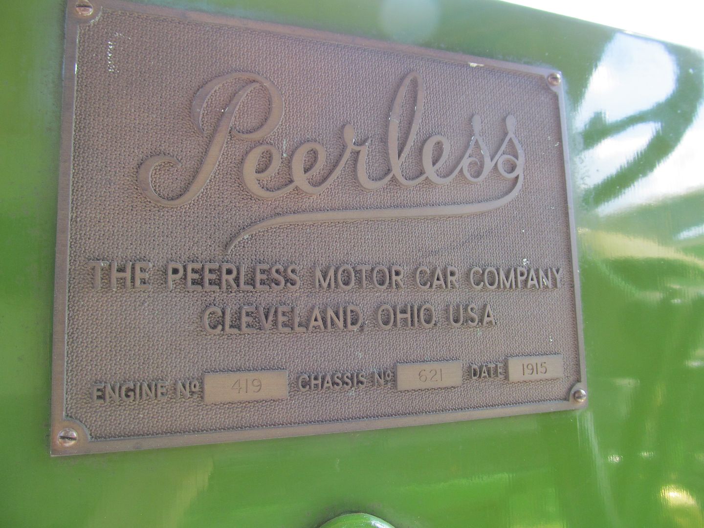
We don't have this plate for ours and are going to have to make one. Can anyone tell me how they produce the background texture on a casting like this? Is it a sheet of material cut around the letters or maybe with letters stuck on with a thick glue? I really don't know but a lot of old plates have this style.
Steve
-
I have had a look through the catalogues and have ordered a pair of LT 1 7/8 thrust bearings. These are exactly the right OD and are big enough for a 1 1/2" bore bush to be pressed into them. Dad will turn up the bushes from bronze and just machine a shoulder to locate the bearing at the top. This should give us a good reliable solution with a minimal use of material which Father tells me he already has in stock from a lucky buy at some autojumble. The next step is to decide whether the king pin should be skimmed or is good enough to use as it is. This will determine the size of the bore.
Steve :-)
-
I think the spoke pattern depended on who supplied the wheels. We have sets of both but chose the Y-spokes because we liked them better. Our front wheels are stamped 'RS&J' on one and 'S&C' on the other. I take these to be 'Ransomes, Sims and Jefferies' and 'Shrewsbury and Challoner' but stand to be corrected!
The chassis is not a Subsidy type, like ours, as the wheelbase is a foot longer and the hole drillings are quite different.
Steve
-
pattern making as well....although i think what Steve has acheaved in the Dennis thread was outstanding...
You are too kind. I am just a backyard bodger who manages to get the required result in the end. I am not brave enough to set up my own foundry. I shan't live long enough to do everything!
John. That is quite some trip. I am so pleased that you have got the right wheels. They will really make the job and are undoubtably a boost to morale as well. We are looking forward to seeing the finished job, whenever!
Did you get a picture of the four wheel drive tractor or can you remember what it was?
Cheers!
Steve
-
I have the great good fortune to have a few days off this week. Mostly, they are dedicated to chores but I did find a couple hours to go in the shed yesterday and have a look at the engine breather. This is a simple bronze elbow, bolted to the top of the crank case and directed into a thin steel tube which brings the hot air from the exhaust manifold to the inlet to the carburettor. There is no seal. The casting just pokes into the side of the tube. Over the years, vibration of the tube has eaten into the side of the elbow.


Step one was to cut the end off and trim it back with a file.

Then I turned up a new end in gunmetal.

Silver soldered it on. (My favourite process!)

Dressed it off with a file so it is all ready to fit. Unusually, the joint is showing but I don't think anyone will notice.

Back to the chores!
Steve
-
Yes, just like that!
Steve
-
On another note... its great to see the engine going together - I cannot wait to here it run. You mentioned scrapping in the bearings - are they cast-in-place Babbitt or are the bronze backed Babbitt shells?
Best regards,
Terry
The shells are solid white metal castings with no backing. They are about 1/4" thick and simply dropped into the crank case and onto the ends of the rods. I have not seen them like that before!
Steve
-
that gasket material you have used on the crankcase inspection covers....is that stuff made by flexitallic?....as they are fairly local to me (cleckheaton)...
I don't know who makes it. It came in a roll from Beaulieu Autojumble years ago!
Steve
-
Great line up,,,, would be looking even better with appropriate Peerless in the same uniform:cool2:
One day, one day! Thornycroft first!

-
We wish you could have been there too. We are all becoming very popular at the moment! The Crossley looked splendid with the wreaths on your wonderful trailer.
Cambridgeshire is pretty flat, Doug, so we could happily cruise at 12-15mph. Probably achieving 5mpg or so.
Steve

-
Sorry, no video yet but I have been sent this pic. It works!

It runs well, I understand but is suffering from an oil pressure of 165psi when it should be around the 20mark! The relief valve is due for investigation.
I went to the museum a fortnight ago with the magneto we have had rebuilt for the Thornycroft as I knew it's history. I started to fit it but thought I would have a look at the drive key position compared with the contact breaker to see if it needed re-timing or I could just fit it and this is what I found with the key straight up in both cases:

Much to my surprise, the contact breaker cams are in quite different positions and I don't understand why this should be so. The RH mag is my Simms SR4 (clockwise) and the LH is the Museum's Simms SR4LX (clockwise). Can anyone explain this to me? Does the SR4LX have an anti-clockwise cam ring fitted? I looked for alternative fixing holes for the cams themselves but none were evident so it is a bit of a puzzle. Something else I would like to ask is can anyone tell me the difference between an SR4, an SR4LX, an SR4LEo r an SRM4? I'm sure there is a difference but it must be quite subtle.
Once my mag had been fitted, the lorry gave a chuff, almost immediately but refused to run further. Since then, the lads have got it going but I won't hear the story until the Shuttleworth Old Warden show tomorrow. The weather is not looking good but I am sure we will find something to talk about! I will post some pics in due course.
Steve
-
I hear that the Maudslay ran for the first time today. When I have the full story, I shall pass it on but it is now all set for the WW1 day at Old Warden on Sunday. Praying for a dry day!
Steve
-
There is no indication of an impulse coupling and we have just a standard vernier type. I have gone through the Museum stores but with no luck. I have been looking for one for the Thornycroft for when the time comes but they are like hen's teeth, it seems. There are two plug holes in each cylinder but no signs of a distributor of any sort to enable trembler coils to be used.
Actually, the magneto arrangement is quite bizarre. One gets the impression that the engine was drawn up and the magneto forgotten entirely! As a result, it is on a bracket bolted to the chassis and chain driven from the front of the crank. Not sure what this is doing to the earthing but we have run a wire from the bracket to the block to try to help the spark a bit.
I went along yesterday and the lads were playing with the inlet manifold and the valve timing. They wanted to check that the manifold was sealed properly but unfortunately, broke a stud getting it off so there was something else to fix. They also reached the conclusion that the camshaft was one tooth out so they will have a go at that next week as well. We didn't get the opportunity to try to start it again.
The joys of old engines with no manual!
-
Yes, I did file them off again but not quite so brutally!
The engine was finally set up on Thursday and initial attempts were made to start it. It was, not unexpectedly, very stiff and despite having a number of people on the rope, it did not run. I went along yesterday after work and we had another go but it still won't start! Not even a 'chuff' which is very disappointing. It appears to be getting fuel OK but the spark is very weak. The magneto has been checked by a specialist and found to be OK but it is the electrical system which remains in doubt. We plan to try changing firstly, leads, then plugs and then to a known good magneto and see what happens. It will go eventually!
After all of that, the engine is noticeably freeing up and one person can swing it now but, gosh, do I ache this morning!
Steve :-)
Sorry. Forgot to take the camera.....
-
All good progress and nice to see. How did you cut the spiral grooves in the shaft? The pitch looks very large for normal screw cutting. My approach would have been doing them by hand with a pencil grinder following a rough spiral marked with a pen but yours are a proper professional job!
Do you think the phasing of the ends is deliberate or accidental? if the gearbox output flange and the differential input are not parallel then you would need some phasing but I am not sure how to calculate it.
Thanks for sharing!
Steve
-
Here's another one.

-
Yes, exciting times. They hope to start the engine in the next week or so. In the mean time, here are some more pics of some of the things we have done.
One of the lads has made up the fuel tank and soldered it up. It has been tested to 5psi.


I then took on the lamp brackets. These had been bent outwards to accept some bigger electric lamps but we want to fit some Lucas 742 oil lamps.

The first task was to straighten them using some heat and the vice.

It can also be seen that the prongs had been hacked about so I cut them off and turned up some new ones.


After milling the end square, I drilled a pilot hole using a simple jig to align it. The underside is drilled to the diameter of the prong.

Then they were simply silver soldered on.

At this point, it became obvious why the sides of the spigots had been filed off!

A final clean up and ready for painting. One more step in the right direction.

-
Thanks Chaps.
Number one project at the moment is to give the Dennis a permanent home but local authorities just don't understand the needs of the average lorry restorer! I am trying to fit in some time making bits as well as taking the Dennis out and this earning a living really gets in the way too!
I am pretty sure that the big radii only occur on the ends with just the corners broken elsewhere. Interestingly, our original plates have square holes in the centre whereas the Carlton Colville ones have round ones.
Some pattern making is planned next.
Steve :-)
-
You have a wonderful shed, Cel. So many interesting things everywhere!
There is great joy in using old tools but I am pleased to see some guarding on the bandsaw!
Wonderful progress as ever.
Steve
-
Our next outing will be to the Shuttleworth Collection WW1 flying day on August 10th. The three of us are going together again. I have also been gently encouraging some more friends so we may well see two more Great War era three tonners making a total of five.
A rare sight if it comes off!
Steve
-
Thanks Caddy. We had a great day thanks to all the organisers. Tim has posted some photos here:
Steve


WW1 Peerless Truck
in Pre WW2 vehicles
Posted
Wax is an interesting idea. The letters could just be pushed into it which would give the crisp edges. If the letters had long pins and the wax was a significant depth, they would be held well enough for a master to be cast.
Someone will know for sure somewhere!
Thanks!
Steve