


Old Bill
-
Posts
1,670 -
Joined
-
Last visited
-
Days Won
33
Content Type
Profiles
Forums
Gallery
Blogs
Events
Articles
Store
Downloads
Posts posted by Old Bill
-
-
Everything we take off is kept until the end. Real scrap, bushes and pins and such like will be binned but the old pistons will be labelled and boxed and go into store. Silly really but they might be useful to somebody one day.
Steve :-)
-
One thing the lorry is short of is a proper period steering wheel. The one it has, has been 'adapted' but does not fit very well and looks too new. From the best pictures we can find and looking at other Maudslays in the museum, it appears to be remarkably similar to the one we should have on our Thornycroft so Father had two castings made with one allocated to the Maudslay.

To attach it, I have made a 3/4" BSP nut and spigot to be attached to the column.


Today, I set the wheel up on the faceplate and bored it through to fit the spigot which has a 4.5° incl taper and a keyway. I had the spigot available to try in the hole in order to get the depth right and allow some space for the nut to pull up.


Finally, I cut the keyway using a boring bar with the bit ground to suit the slot and planed it out by winding the carriage back and forth. It was a bit laborious but effective.

Once I have faced the front, I shall present the wheel to the volunteers for someone else to polish the casting!
Steve :-)
-
Hi Andy.
No, we haven't fitted a gasket under the block. We had some debate about it but as there was none there when we took it apart and it isn't mentioned in the parts book, we decided not to. It would, however, have helped with the tappet clearance!
Steve :-)
-
We started today where we left off yesterday by fitting another piston to number two rod, securing it with the spring clip without breaking it and then by fitting the remaining rings. This all went well and the rod was bolted to the crank and tightened right up. This showed the bearing to still be a little tight but a couple of scrapes soon sorted it and the nuts were secured with split pins. Two rods down.

A brief intermission was taken to salvage four spring clips from the other pistons ready for cleaning up and reducing in size to fit the smaller pistons.
That achieved, we decided to fit one block to protect the rings and see how it all looked. The chain block was used to raise it and the engine was wheeled underneath.

After wiping the bore and pistons with an oily rag, Dad slowly lowered the block whilst I poked the rings in with a piece of wood and a screwdriver. I remembered from the Dennis that pushing the rings with ones finger tips is not a good idea as the block can suddenly drop, trimming one's finger nail, if not more!


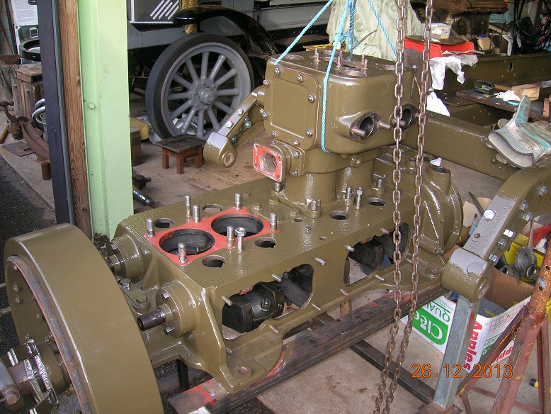
Once fully down, the block was held with 5/8" nuts on the new studs made earlier. The cam followers were also fitted and clamped down.
At this point, I wanted to grind the valves in but was dismayed to find that our re-cut valve seats have dropped so far that there is no longer any tappet clearance.
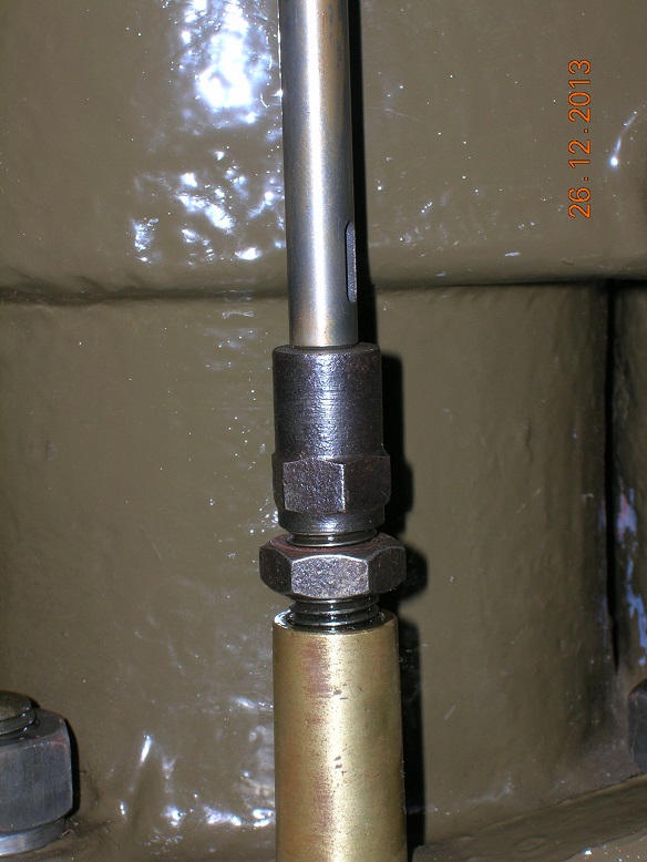
I need to find about 0.060" and propose doing this by trimming the end of the valves and possibly facing a little from the tappet. I would prefer to trim only the tappet but there is just not enough metal there. Another challenge to be overcome!
Steve

-
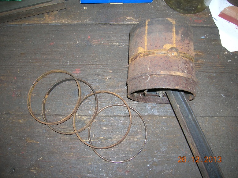
After fitting all the gaskets and covers, the next step has been to 'gap the rings'. The rings we have are for 110mm bore which is slightly bigger than the 4 5/16" of our liners so I have dressed the ends back to give a clearance between them of 0.012". A gap of 0.002-0.003" per inch of bore is recommended on the scraper ring packaging so I have simply followed that.


Unfortunately, after completing fifteen rings, I had a disappointment when I found that the last scraper ring was too small and already had a gap of about 3/8".

All of the packets were correctly marked but one is undersize. I shall have to contact the supplier in the New Year but it is a bit of a disappointment as we cannot do much more to the engine. I can do a bit though so I have fitted the first piston to a rod by pushing the gudgeon pin into the newly honed bore. It went beautifully and I had then only to fit the re-sized spring clip to secure it

Disaster! I have obviously not got my heat treatment quite right and two of the clips broke in my hands. Closer inspection revealed cracks at the breaks but it was most annoying.


I softened the two remaining clips a bit further and my third attempt at fitting one was successful and worked a treat.


Then the other rings were fitted uneventfully and the rod was ready for the engine.

When fully torqued, the bearing was a bit tight but another blue and scrape sorted that and the rod is now secured and pinned. I will try to do another tomorrow and perhaps we can at least get the front block fitted.
Steve :-)
-
Thanks Chris. That is a very good piece of guidance. I'm just going out to scrape a little more as I have torqued up the first big end completely and it is just a little too tight.
More later. Happy Christmas everyone!
Steve:)
-
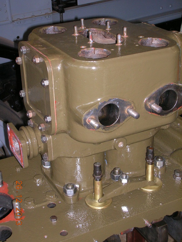
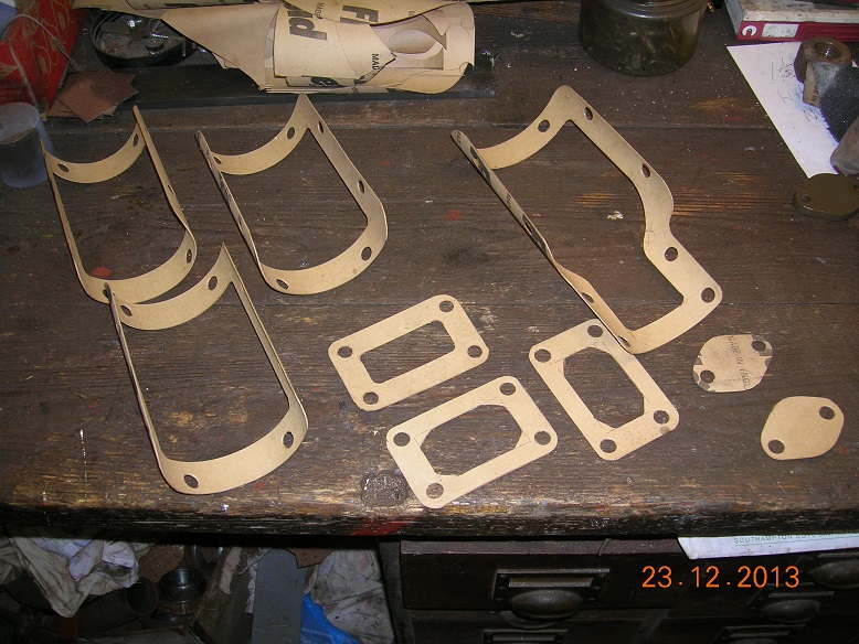
Next part of the job is to assemble the blocks. Firstly, all of the necessary gaskets were marked out and cut using a pencil, rule, Stanley knife and wad punches
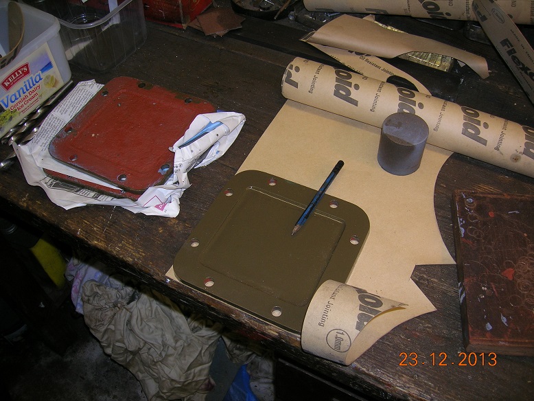
Then the threads were cleaned up with a die nut before fitting the first cover. As the mating surfaces were so poor, red Hermetite was used to help the seal.
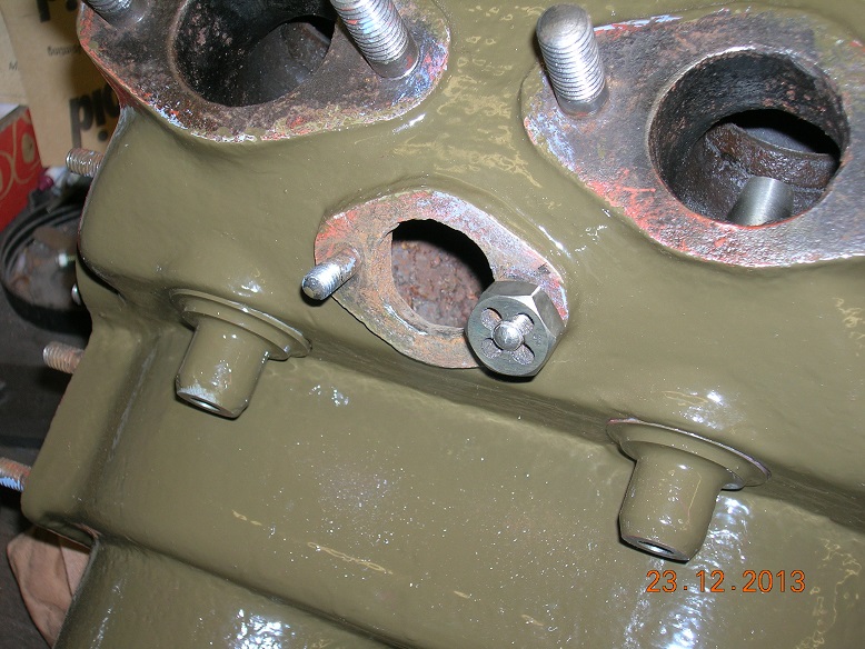

Then all of the other covers were fitted including the pump mounting casting.


This has proven to be more than a day's work but the results are quite pleasing. The next task is to gap and fit the rings before permanently setting up the rods on the crank.

Plenty to do tomorrow!
-
Thanks Richard. That's an interesting item I have not come across before.
Should the rods fall around the crank when fully tight or should there be some resistance? At the moment, I have two which fall freely and two which require a slight push. What I really need is to see an expert do it and then feel for myself!
Steve.
-
The time has come to start putting the engine back together! The first job, of course, was to find the bits which proved to be a bit of a challenge so it will be good when they are all bolted together again. We started by hanging all of the con-rods on the crank and nipping them up to see how they fitted.

They were not excessively worn but all had a little sideways wobble and a longitudinal clearance could be felt when pushing them up and down. To remedy this, I filed 0.006 - 0.008" from each shim in stages until when we did them up again, they gripped the crank.

We blued them and rotated them around the crank in turn to find the high spots in the white metal which were then scraped back and the process repeated until they could be rotated around the crank smoothly without wobble.

One question I would like to ask is how tight should they be? I just keep going until I think they feel 'right' but I have no idea what that should be! I must say, though, that we were subject to official supervision throughout the process.

Now I am going outside to do some more. Gasket fitting today!
Steve :-)
-
Doug.
When we first got the chassis, it had been protected underneath a shepherd's hut and there was one good patch of army green which a friend of mine brought up with Brasso. The third batch of paint that we bought for the Autocar and all subsequent batches have matched it exactly so we are confident about the colour of our British vehicles. We used the same paint on the FWD because we have no better information for a US lorry but suspect that it may have been lighter originally. Leaving the Thorny chassis outside under a sheet for twenty years had, unfortunatley, destroyed that patch of original paint and the sand blasting finally finished it off.
Steve
-
Mind you, military vehicles were grey with black lettering up to about 1915.
Steve
-
Yes, it certainly feels better to be able to put things together, if only to reduce the amount of stuff on the floor around us!
Steve :cheesy:
-
That would be interesting to see. We had a slotter at work but it was scrapped a few years ago (it was marked 'War Finish'!). I never saw it in action. I worked at Aveling Barford for a while and they splined gears by pulling a single long broach through. Long means over ten feet! I never saw that in action but the tooling was all stored around it.
Steve
-
Thanks for all the ideas Chaps. I will let you know how I get on!
Steve
-
Wonderful job! Thanks Cel.
Steve
-
Hi Cel!
Great to see some positive progress again! Please can you tell me how you went about re-metalling the big ends? Which bits did you heat and did you 'tin' the shells? I did the Autocar years ago and they have survived, more by luck than judgement I think.
Do I understand correctly that you built up the main crank shell by adding white metal a bit at a time with a soldering iron? That sounds quite a difficult procedure which I would never have thought of doing and I would love to hear how it went.
Keep up the good work!
Steve :thumbsup:
-
An interesting idea. What is the 'right consistency'? The cork has to hold together as part of the tap. I don't want it falling apart and go losing a tankful. We have to pay twice to fill it as it runs beyond the maximum spend!
Steve
-
That's an interesting thought Andy. Laying my hands on liquid nitrogen might be a bit tricky though! I am currently thinking of grinding it by using the Dremel with a small wheel, mounted in the toolpost. I have managed to drill a hole through a reconstituted cork from a bottle so I might be able to mount it on a mandrel and attack the outside. A bit of experimentation is needed I think.
Steve
-
What a wonderful piece of work! I am looking forward to seeing it in the flesh!
Cheers!
Steve :thumbsup:
-
-It appears to be have been made out of steel, with a separate rim, rather than cast in one piece in aluminium. Perhaps the need to protect steel spokes from rust might explain why they are coated as well as the rim in this case?
I'm afraid we are rather taking some liberties with this wheel. It was originally a steel tube rim surrounding a cast steel centre, not aluminium, and coated with celluloid or similar all over including the hub. We are using aluminium just because it is the easy way out and it will be disguised by the powder coat. Of the ones we have seen, all are in poor condition except the gun lorry of course. Unfortunately, when I last saw that, I didn't think to take any pictures of the wheel!
Steve
-
Guys, how are you going to coat the rim and spokes?, I have an Austin 7 steering wheel needing the same treatment.
As Richard says, we plan to use glossy powder coating again, just like we did with the Dennis. That worked well at very reasonable cost. This picture shows it on its return but before cleaning and tidying the finish at the ends of the spokes.
Steve

-
Steve,
How exactly do they cast this? I was puzzled by the Dennis wheel and the recent pictures have raised the same question. There must be a simple trick but what is it?
Hi Barry.
I haven't actually seen it done but I think that the wheel is placed face down on a board with the drag around it. It is then packed with sand completely including under the spokes. When the drag is turned over and the board removed, the moulder cuts the sand away down to the centre line of the pattern using various spatula like tools. The cope is placed on top and a sprinkle of parting sand is applied before filling up with more sand. When that is lifted off, the pattern can be removed.
This approach is fine for the one-offs that we do but I think he would probably want a backing piece made up to go underneath if he was doing very many.
I remain to be corrected!
Steve :-)
-
Very nicely done. A random thought, but you could probably have used acrylic false nail tips for those finger grips!
Hi Andy.
I hadn't thought of those. Rather outside of my usual shopping experience!
 I did spend some time trying to find something that might do the job but the brass was the only solution that I could make work. It doesn't Araldite very well though so I may lose some in the moulding process. We shall see.
Steve
-
How amazing. You can learn something new here every day!
Steve


WW1 Thornycroft restoration
in Pre WW2 vehicles
Posted
I'm sure that would be fine but I don't want to part with anything until we have completed the job. I have been caught that way before!
Keep in touch!
Steve :-)