fv1609
-
Posts
11,567 -
Joined
-
Days Won
35
Content Type
Profiles
Forums
Gallery
Blogs
Events
Articles
Store
Downloads
Everything posted by fv1609
-
I'm afraid you don't Tony :-D
-
What's this all about?
-

introduction INTRODUCTION from John Attlee
fv1609 replied to attleej's topic in Introductions & Welcomes
Welcome John I have spent many a day rummaging through the Museum's EMER collections as Brian will testify :-D -
restoration Now the work will start with 13BK33 FV1611A
fv1609 replied to Rover8FFR's topic in Blogs of MV restorations
I think the holder doesn't get a mention because it is out of view or obscured by the fire extinguisher in all illustrations in the UHB, ISPL & EMER Technical Description. Out of sight out of mind, so it gets forgotten about! In fact the EMER runs out of steam & goes a bit wonky at the end of the description on internal fittings because it shows the driver's door with the fire extinguisher & Pouch Drivers General Purpose. The illustration is the door of a Hornet not a Pig. The Pig door has the bracket for the First Aid kit. The earliest CES I have is 1969 & the machete is not included at that stage. It is included in Hornet CES of 1966 & shows: "Machet 151n. blade KE/5110-99-003-8127 Machet sheath KE/5140-99-003-7818" -
restoration Now the work will start with 13BK33 FV1611A
fv1609 replied to Rover8FFR's topic in Blogs of MV restorations
Yes it is -
restoration Now the work will start with 13BK33 FV1611A
fv1609 replied to Rover8FFR's topic in Blogs of MV restorations
Well what you bought were Dale's, this panel is mine & to be used in my refurbishment ok? Not a coincidence the ERM is deliberately constructed that way for them all -
restoration Now the work will start with 13BK33 FV1611A
fv1609 replied to Rover8FFR's topic in Blogs of MV restorations
I do actually have a spare one of those complete with VAOS label. But anyway yours looks fine & you'll have to make your own label First digit of 5-digit serial number '2' on yours merely indicates it was originally built as a FV1601 whatever later conversion took place FV1611, FV1613, FV1620, FV1621, FV1622, FV1623, FV1624 the basic chassis number remained the same. '3' indicates it was originally built as FV1602 FFW whatever later conversion took place ie FV1612 '4' indicates it was originally built as FV1604 '9' indicates it was originally built as FV1602 FFW but rebuilt as FV1609 & received a new chassis plate with '9' replacing '3' Start of sequences 20001 00 BK 01 GS (originally CT) 32311 23 BK 11 FFW 43301 33 BK 01 Wireless Light -
restoration Now the work will start with 13BK33 FV1611A
fv1609 replied to Rover8FFR's topic in Blogs of MV restorations
First digit is a coincidence will explain later. Four digits are by design. -
I would have thought the driver would have been RCT rather than a medic.
-
Silly me I was forgetting this is 1963, the 4th antenna mount was introduced from Oct 1964.
-
Mk II you are a tease you'll get everyone confused, but you are correct it is indeed that. Yes I was forgetting yours has one of those covers. I do have a very rusty example but can't really justify fitting it. If it was a post-factory mod then I suspect it is lost for all time in EMERs WV N257 Nos 1-44 (less 37) that were cancelled & destroyed circa 1968. I would dearly like to see what those 43 EMERs contained. Every WV EMER set I have examined has dutifully been devoid of these instructions. :cry: Yes tart it up a bit before you show it to Jim. Perhaps later he could demonstrate to correct way to paint it for you
-
Thank you Wayne for sourcing these. Jim is to be congratulated in having the foresight to take decent pictures showing the ERM & with a decent camera. I note that the FFR has not yet acquired its 4th antenna mount so strictly speaking may still have been a FFW. I note the fairly rare rain cover (for open windscreen) over the horn/headlight switch. I have a hunch that was on early Sankeys & not on ROFs. But not seen enough examples to be certain.
-
There were broadly two Series II ambulances those based on Rover 9 & those on Rover 11 I sent the Rover 11 UHB supplement to the mods last week for posting in the section with other Rover Ambulance pdfs. So it should be up soon.
-
But who would have the courage to display that scheme at a show? It certainly would be tempting
-
It is indeed. I had a bust shaft on a Birfield & a mangled up pinion wheel. So swapped the whole rear axle although that was missing a wheel station so had to move that from the old axle. All good fun.
-
Not very good but it just about gives the idea.

-
Excellent stuff thank you. Keep em coming! That's the third Christmas variant I have seen. I have also seen a Christmas Flying Pig converted to a desert island in the summer with palm trees & the Pig wearing sunglasses!
-
Usually the resistance of the ballast resistor is equal to the resistance of the coil. In a 12v system the total resistance of the two in series is about 3 ohms. This allows about 4 amps to be switched at the contact breaker, this is the practical limit of reliability for a mechanical switch like this. (A switching transistor in an electronic ignition system can switch much higher currents & this allows a coil to have a lower resistance, carry more current & designed to give more HT from the additional magnetic field produced) A ballast resistor has two functions. 1. During start up the ballast resistor is short circuit & applies the full battery volts to the coil, although this may be a bit lower due to the drain of the starter motor. Depends how good the battery is. Prolonged hanging on the starter button (more than 10 secs) can overheat the coil. (A feature not actually utilised on Land Rovers with a ballast resistor) 2. To boost the HT output. This can be in high performance vehicles but in MVs particularly in screened ignition systems operating on 24v. Adding resistance to the primary circuit offsets some of the effect of inductance of the coil. It has the effect of reducing the time constant of the circuit. The result is that at high revs the engine can perform better by a more rapid collapse of the magnetic field in the coil when the contact breaker opens. This is used in screened systems to try to compensate for the HT that is lost by trying to 'charge up' the capacitance in the screened cables. So in summary if you vehicle is 12v & the resistance of the coil is about 3 ohms you don't need a ballast resistor. Capacitors (condensers) As these have been brought into the discussion it is important to differentiate between the two types that may be found around an ignition system. There will often be a capacitor in the feed to the coil (SW) this might be rated a bit above the normal vehicle voltage say 25v. Its purpose is to try to dampen down some of the interference from the contact breaker from entering the vehicle wiring system. It is of limited effect & in FFR vehicles a more sophisticated filter is often built into the ballast resistor enclosure. The important capacitor is the one in or connected to the distributor this is rated at about 500v, as the back EMF in the primary winding when the contact breaker opens is around 300v. The small spark at the contact breaker is the effect of this voltage. Without it the points will wear more rapidly because the greater spark occurring when the coil is switched off will be less abrupt there will be a reduced HT output. The capacitor can have the effect of improving HT output by 30% compared with no capacitor. Capacitors rarely fail outright but the insulation will deteriorate with time even if unused. The only way to get a reliable assessment of capacitor performance is to test it at its rated voltage. Trying test with a multimeter might only weed out a few absolutely awful capacitors, it will not distinguish poorly performing capacitors that are contributing to poor engine performance.
-
Looking forward to it. As always there is an open invitation to bring any ignition components for testing particularly screened systems. Very few people take me up on this, there is no catch, no fee. I can test distributor capacitors, rotor arms, coils, insulation breakdown in screened cables, sparking plugs & measure HT up to 20Kv. Although I have previously tested coils by resistance, inductance & insulation breakdown. I have now built a device to run up an ignition coil so you can see the sparks fly. Also I can now measure insulation leakage up to 200 gigohms using a 5Kv source. One might assume resistance stays constant but as far as insulation breakdown goes the resistance goes down with increased voltage. The 5Kv source allows sparking plugs to be observed as to whether any spark they produce is actually where it is meant to be! I will be with my Pig & probably the only one there - that is Pig I mean
-
At least the TRB on that Hornet was always pretty tight. Although not always so with the torsion bar securing bolts which needed constant checking.
-
Um well yes. It was a 14-year relationship that cost me many thousands, one doesn't forget these things.
-
That's a super job Luke & I look forward to seeing it evolve. Given that you are clearly doing a precision job there are few points I should mention how the storage Hornet differs from the display one. Apart from not having that cage(!) I imagine you can get freer access without visitors wanting to climb in as well! IR Lamp boxes - I made these they are closish copies but the actual construction may differ from original Main arm latches - These steady the arm when driving & are designed to fall downwards once the arm is raised. I push fitted two wooden blocks so that the latches were held open once the arm was lowered again.This avoided someone standing underneath holding the latches open. Exhaust system - As you have realised the front exhaust system differs from the rear exit on prototypes & Pigs. For this there is a distended belly plate. A replacement exhaust was impossible to find. The silencer I fitted was used on a Bedford Midivan & the tail pipe from a Citroen car. You will note that the original has more of a sweep to it. Main ram canvas - The original had rotted through I had a saddler make up a copy but the eyelet arrangements may not be accurate. Tilt ram - This was seized & the seals etc no longer available. I had a new metric ram made, few would know but it does differ a little. Repaired locker - People would tell me that it was crude, but that was an in service repair NATO socket - I fitted that as I used to tow a trailer to shows. Although there is a NATO hitch (still missing on the display one?) that was for recovery, towing etc rather than for normal use with a trailer. Fin & wing storage - I think some of the slide rails in the rear are missing. Best to check with the display one. Battery tray - This was missing. I made a sliding tray I think quite unlike the original. Based on the materials I had & ease of use. Transfers - The large coloured 2 RTR crest although authentic is wrong for the Hornet, but it was all I could get at the time. I was able to get one transfer that is correct being the small silver crest on a black square. Mud flaps - Not sure if those are original I think I may have made those from the floor of a Fiat Panda. The original has several broad vertical ribs. Other points. The separation firing kit on the wing is of course is detachable. One quite famous book dismisses it as "may not be original". The anti slip tracks under the upper jerrycan although now pointless are original as it goes back to the time before the extractor fan when the jerrycan was mounted on the off-side. Leave the bridge plate blank. The display vehicle for some reason shows '7' when it should be class '6' but the bridge class was never marked up in service. I don't know whether you have decided to have Mk1 or Mk1A missiles but the venturi differ as does the wing illumination flares/lights. I have seen these mixed up before. But of course it will depend as with the markings what time period you want to represent or whether there will be an option for different markings. Anyway good luck with the project.
-
Luke I'm not sure that the information you have been given is correct. There were two main batches of production Hornets being completed in July 1962 & January 1963. Both of the those Hornets were part of the second batch. The prototypes were built in mid 1961-early 1962. The wooden bodied mock up in 1958. The display Hornet 06 BK 66 was struck off to the RAC Museum on 23/10/70. The reserve Hornet 05 BK 02 was struck off to the Airborne Forces Museum on 23/7/70 & was with at least two other museums before it appeared at Bovington. But I'm afraid I'm no nearer to answering you query about the racks. You could consider making a model of a prototype. Then you need not have those large racks & I could provide a photo of the power unit & no need to make the fan cowl, smoke dischargers, IR headlights, separation kit on the wing, nullometer etc :-D
-
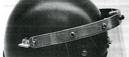
I sold all my Army helmets but my recollection is that the ART helmet had a visor with a narrower arc than the turtle. I don't think there was a visor for that second helmet. The one below NI Combat Helmet of which 2,300 were issued for troop trials for all units (was to be the forerunner for the "new general service combat helmet"). But you don't see to see many of this type around.

-
Similar but I think that you will find the visor for Anti-riot helmet with visor (ART) civilian pattern in your picture & below will be too narrow for a turtle.