


Danny P
-
Posts
299 -
Joined
-
Last visited
Content Type
Profiles
Forums
Gallery
Blogs
Events
Articles
Store
Downloads
Posts posted by Danny P
-
-
You're right, haven't answered you but were thinking you would send the picture anyway at some time. Sorry for my misunderstanding. I would love to come to Arnhem but am afraid the truck will not be ready by then. So, a picture and some measurements would be great as an alternative, but please take your time Davey as I appreciate your help.
Thanks,
Danny
-
Hope I'm not too pushy when I remind you both again to my questions. No further responses so far!
Who does not ask will not become wiser! :blush:
Danny
-
Richard,
That door beam is really a piece of art. I had to make new ones because of the woodworms that made cardboard from it. It is not a straight beam but has a certain angle. Yours looks original but straight and therefore that little curved wooden front piece towards the wing will be outside your door. You will not be able to fit the angle iron towards the bulkhead and door beam in this way. That front piece should all rest on that curved metal plate where the wing goes to and with some canvas between it. If you need some pictures I can take some if you like?
Danny
-
Davey, how many slotted blocks for the battery cable are fitted and at what location were they fitted? Would it be possible to get the measurements of those blocks.
Jeremy, would it be possible to get the measurements of the pick axe blocks, if you have some time?
Thanks,
Danny
-
Jeremy,
Could you give me the cutting list if you don't mind? Trying to safe some money on my project. Postage costs to the Netherlands always annoys me unless you can let the blocks float through the channel.

Thanks in advance,
Danny
-
On the left picture the pick axe blocks which were fitted in my late bedford mw which, to my opinion, are poor reproductions. On the right side a picture from the internet of some, I believe, correct reproductions for the (early) mw. Does anybody know if these blocks were made according to a certain standard or would they differ in each truck?
I might be asking too much for the original dimensions of these blocks?

Danny

-
Jeremy,
You have done a great job in a relative short time! My compliments to you!
Danny
-
Type of distributor on my truck is DVZ6A. There are some more numbers on it but can't get close to it because the vehicle is parked too close to the wall. Hope this will help a bit.
Danny
-
There is a data plate with the chassis number at the left side of the vehicle under the hood and a plate at the top of the dash with the contract number.

Danny

-
Andy,
If I'm right there is a number on the distributor. If you need that number I can have a look at mine.
Regards,
Danny
-
Thank you both, Andy and Jeremy,
On reflection it seems to me unlikely that the box is (spot)welded to the floor. It would not be practical to do it either before or after the placement of the floor.
Many thanks,
Danny
-
Box finished by spot welding the parts!


Just need to know if the folded edge at the below side of the box is (spot) welded to the floor. Andy ......?
Danny
-
Many thanks for your help Andy!
Could you do me one more favor? If you look into that box you can see a folded edge at the bottom. Is it spot welded to the floor or is it loose?
-
No responses so far! Hope somebody will help.
Another additional question; is this box also spot welded to the cab floor plate or is it only bolted to front board of body and side panel?
Thanks,
Danny
-
The bottom of the box behind the passenger seat is rotten so I have made a complete new box for my bedford MW(picture 1). The question now is, how does the folded edge of the small side plate look like at the bottom of the corner (picture 2)? Is it also with an angle of 45 degrees just like the top (picture 3)?
Picture 1: new box

Picture 2: rotten bottom of box (how does folded edge look like at bottom?)

Picture 3: folded edge at top of the box with an angle of 45 degrees

Another thing is, the box is bolted to the front board of the wooden body with, which I believe 5 carriage bolts instead of six. The lower hole, which is the sixth, is smaller and is not used because it is in conflict with the floor of the body. Any thoughts about this unused hole and its size? I have not drilled this one in my new box, but if it is original I will do so.
Hope somebody will help

Danny
-
Yeah, that was the most obvious answer I was hoping for. Thank you Andy for helping me with this!
Danny
-
Can anybody help with my last question about the passenger seat of my late bedford MW to finish the job. The "Z"-brackets seem to be welded to the seat but how, spot welded? I can't find any sign of welding on the seat or brackets.
-
Thank you Andy! Do you mean like the picture below? One last question, are the "Z"-brackets spot welded to the seat or at a different way? A picture of yours would be great!

-
Thanks, that will do!!
-
Thank you Ron and Jeremy! What diameter do I need. Do I need a certain oversize, soak them in water to soften and fit?
-
Those four small holes are not original to me. But look at the back if the four small holes have some burrs, if so, they were drilled afterwards.
Danny
-
The corks of the main petrol tap from my bedford MW need to be replaced. Does anybody know the exact diameter and how to make new ones myself? Or would there be a better alternative like rubber?

Thanks,
Danny
-
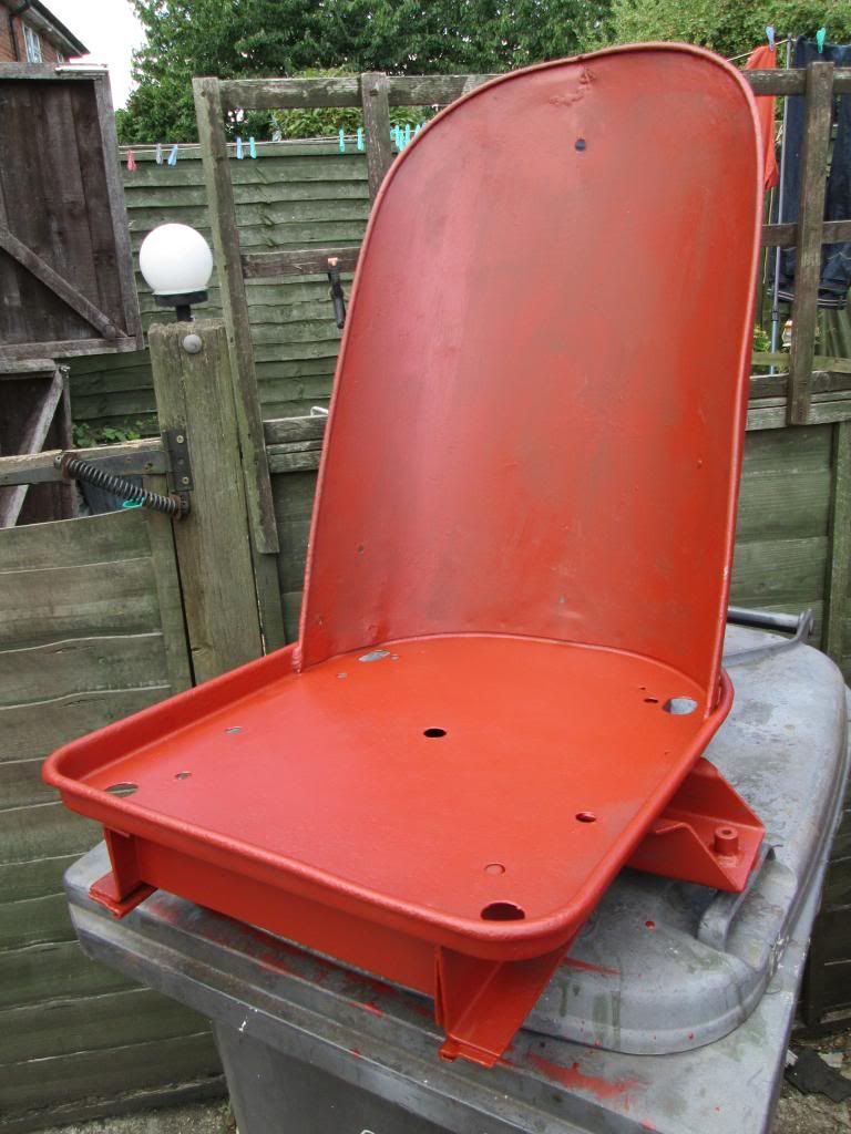
I'm sure somebody can help me with the mounting of the passenger seat in a late bedford MW.
Below the brackets on which the passenger seat was mounted at a distance of about 32 cm from center hole to center hole. The distance corresponds to the welded bolts in the floor plate.
On the second picture is the seat placed on the brackets. You can see the bracket through the smaller hole of the seat but you can also see a small gap indicating that the top of the bracket in not centered to that hole.
So it is a mystery to me how the seat is mounted to the brackets, assuming that the smaller hole as indicated is for the mounting of the seat and assuming the brackets are correct. Can anybody help please?

Remarkably the driver seat is just like my description of the passenger seat (taken from another thread) but has a different structure below.


-
Floor plate of cab sandblasted and primed. Sandblasting of the inner side of reinforcements went very well and I let in some diluted bitumen from different sides and angles for maximum preservation.


For the passenger seat two bolts are welded on the floor plate at a distance of about 12.5 inches. The back of two angle irons were screwed to these bolts. Subsequently, when the seat is placed on these angle irons none of the bigger holes in the seat match with the top of these iron angles.
Before, the seat was attached with some tiny rivets to the iron angles which seems not original to me. You can still see the tiny holes in the angle irons and you can see the line of welded holes in the seat where the rivets have been. CAN ANYBODY PLEASE HELP ON HOW THE PASSENGER SEAT IS MOUNTED?

Danny


cab tool blocks in a bedford MW
in British Vehicles
Posted
Thank you Dave, very useful pictures and dimensions!
Somebody who has the dimensions of the pick axe blocks as mentioned before (1 floor block and to clamping blocks)? Trying to make some progress on the cab now!
Danny