


Danny P
-
Posts
299 -
Joined
-
Last visited
Content Type
Profiles
Forums
Gallery
Blogs
Events
Articles
Store
Downloads
Posts posted by Danny P
-
-
Thanks!
-
Have posted a wanted ad in the past but now I cannot find the option anymore! So, how to post a wanted ad with the relevant prefix?
Thanks
Danny
-
John,
That's a beautiful bedford!:wow:
-
Andy,
I'm glad to see that the bracket is fitted with two bolts but the bracket itself has a strange shape to me. I now have seen several different brackets and still do not know which one is correct. Besides you have the trailer socket fitted where the axle flood lamp should be to my opinion. Oops, and now I see your bracket isn't in the middle of the rear cross member! So is this an extra bracket for the trailer socket? Increasing confusions!
John,
Thank you very much for your help about the chains! How was your test drive today?
-
I was hoping for at least ten links, so this makes sense, otherwise the pin will not come out of course! Thank you for that John!
Hope everything goes well during your road test. Enjoy!
-
John,
Do you know how many links are used for the petrol cap chain and tow pin chain. I assume the chain for the tow pin is longer than the petrol cap chain?
-
Thanks fellows, but the answers confuse!
I have a NOS Butler dif lamp but the fixed bracket on that lamp is not bent in such a way the lamp will pointing down to the dif when bolted straight on the chassis rail?
I mostly have seen nowadays pictures with the dif lamp on a bracket in many variants but like the picture of T Corbin is showing.
The "Bedford authorised service parts" book is mentioning a bracket along with two bolts for fixing the axle floodlamp (see picture below) but also with a remark "no longer serviced". Besides, the length of the bolts in that list is only 9/16 inches which implies the thickness of the bracket would be 3-4 mm remaining (very short bolts and thin bracket then???).

And what about the picture below?

It is showing a relatively long bracket with the dif lamp. You can also see a clip with the electric cable just at the right side of the bracket on the rear cross member. That's the place/hole where the trailer socket is fitted on T Corbins picture.
With this information and the picture above I would say the bracket would be about 1 inch wide and only 3-4 mm thick. But what would then be its total length, and how is it bolted on the rear cros member (angle pointing to the front or rear)?
Who hooks up in this detail?
-
Does anybody know how the bracket for the axle floodlamp/convoy lamp on a late bedford MW looks like (dimensions) and how was it fitted to the rear cross member of the chassis (having two holes for the attachment)? Is the angle of the bracket pointing to the front (like this ┌) or to the rear of the vehicle (like this ┐)?
And what kind of chain is securing the towing yoke pin for a trailer coupling?
Pictures are welcome
Thanks!
-
Yes, still working on my bedford MW restoration project but at a slower pace, unfortunately ...:undecided:
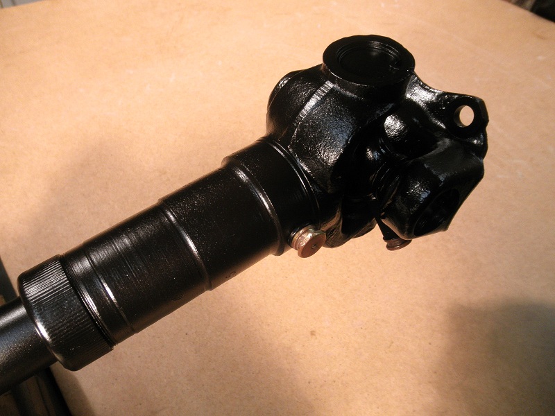
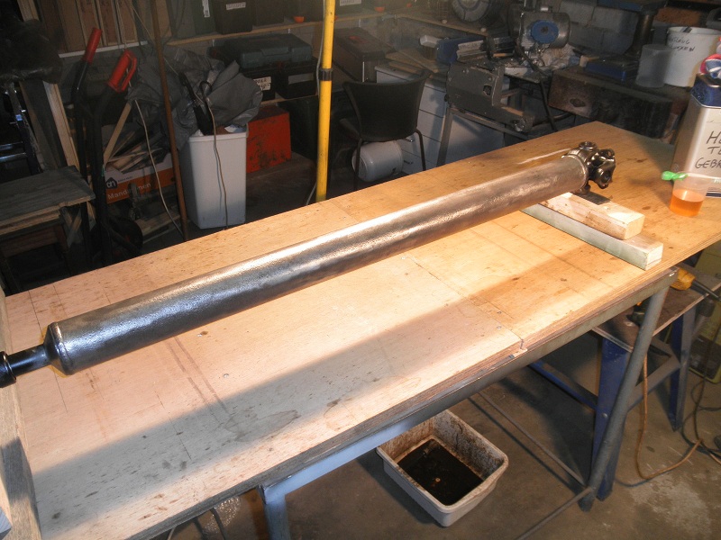
Drive shaft

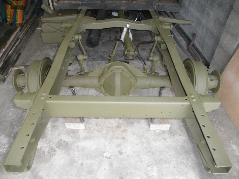
Reassembling the restored parts on the chassis
Drive shaft needs to be connected

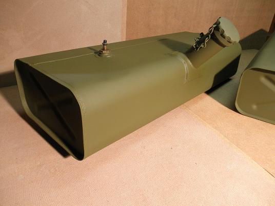
Petrol tank fitted

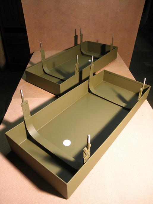
Frame work, perfect fit

Need to finish the rear brakes, handbrake and exhaust. Then the wheels back on and I can once again drive her out of the garage after two years.
-
These pictures once were on the Forum. If I'm right posted by rippo (John). You better ask him for measurements. John, if you don't mind ....


-
Your petrol tank looks OK! Still tin-plated. I used a paint remover paste which acts upon the paint. The paint will swell and can be easily removed. Do not sand blast your petrol tanks because it will remove the tin layer. You will need a special/universal primer which adheres to the tin.
-
Such a nice movie with that camera on a stick, accompanied with the right music! I got a smile on my face looking at it!
Well done!!!!
-
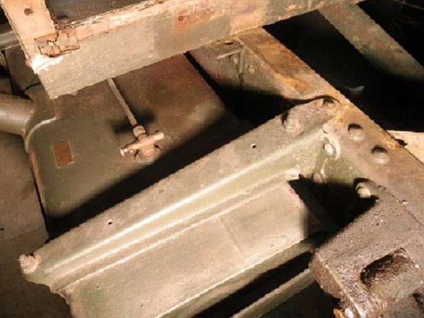
Can anybody help on the dimensions of the spring plate securing the tow pin as demonstrated in the pictures below. I've only measured the total width and length of the plate from an early Bedford MWD which was 5 cm x 20 cm (first picture).
Then I found out that the width of my broken plate must have been 4 cm wide at the side of the two bolts as presented in the second picture.
So I maybe have missed that the plate might be not fully rectangular but somewhere diagonal from 4 to 5 cm?
I have created a new plate which is 4 cm wide and rectangular for the first 5 cm of length at the two bolts side, then diagonal from that point to a width of 5 cm at the end of the tow pin side as demonstrated in the second picture. Is this right or should the plate also be partially rectangular at the tow pin side. If so how many cm?
And what is the dimension of the gap for the pin. I have made it 2.7 cm x ...?
Would appreciate to have the exact dimensions since I hesitate I have done it right and my masterwork was only an exercise!

What material was used for this plate? Is it special flexible spring plate or just iron plate? Just iron plate may bend if you push to hard the pin down!
Thanks,
Danny


-
You can always learn from the pictures during your own restoration project! Not a long time ago I had a question about the exhaust. I was under the assumption MWD's were fitted with the long exhaust pipe ending at the rear of the vehicle until somebody mentioned the short stubby pipe. This MW is also fitted with the short stubby pipe which confuses me again???????
It will be quite a challenge to restore this one!:box:
-
Thank you all for replying, now knowing I will be safe on the road!:drive:
-
Thanks Louis,
Because of my curiosity I've tried to figure out how the brake master cylinder works. As you can see on the picture below there are two brake fluid reservoirs with two different volumes. No.4 for the front brakes, no.8 for the rear brakes. When the push rod is pressed in brake fluid is first taken from reservoir no.8, then taken from no.4.
Consequently more fluid will be needed for the rear brakes and therefore reseroir no.8 is arger than reservoir no.4.
So, in detail, when the push rod is pressed in the primary piston no.9 will build up pressure in primary cylinder no.6; fluid will come out for the rear brakes. Subsequently when the pressure in the primary cylinder is high enough the secondary piston no.5 will move forward and pressure will be built up in secondary cylinder no.2; fluid will come out for the front brakes.
Does anybody agree with my theory? The question that remains: is more fluid going to the rear brakes because of the distance to build up the same pressure as the front brakes?

It's better to know that you understand than to do what you think you know!
-
Just to be sure! I've dismounted the brake master cilinder from my Bedford MW for reconditioning and refilled it with brake fluid.
Then I've tested it by pushing in the cilinder at the push rod side of course. I noticed that brake fluid first came from the outlet for the rear brakes, then with some delay, brake fluid came from the outlet for the front brakes. I also noticed that more fluid flows from the rear brakes outlet than from the front brakes outlet. Is this correct?
-
Hi Jules,
The 900 x 16 Bar grips will not fit your British rims. If you insist you have to shave them about half a cm if I'm correct. There are some professionals who can do that. You should not do it yourself because it has to be correct around the whole tyre!
-
Hi Pete,
Regarding the picture below I assume the MWC had also a long tail pipe!

-
John,
I thought so! Yes, already have the long bolt and distance piece to fit the pipe at the rear cross member. How about the length of the long tail pipe then? 52" developed length, is this correct?
Any body else any ideas about the MW exhaust?
-
I was going to buy a new exhaust for my Bedford MWD when someone told me that the MWD would have had the short stubby tail pipe of about only 6.5" long. I was under the assumption that all MW's would have had the longer tail pipe of about 52" long but these would only be fitted on the MWR, so fumes did not get into the back of the truck where people were operating the radios.
So far I've never heard or read about the stubby tail pipe and therefore I would like to know if this is correct? And why are, as far as I know, all MW's I've seen fitted with the long tail pipe? Maybe it has something to do with the year of production? Who can tell me?
stubby 6.5" tail pipe

longer 52" tail pipe

-
John,
Thank you for that picture of the correct location of the body mounting bolt. Now I can see that there is little space for that bolt because of the muffler bracket on one side of the chassis frame and the petrol tank bracket on the other side of the chassis frame.
Do you also have a picture of the front pipe connection to the muffler? I would like to see how far away from the muffler the front pipe is bent for reproduction.
Thanks
-
Thank you gents. I must admit I was wondering wether to 'wing it', but I will make some further enquiries. I have also emailed Norman Aishe (Bygone Bedford Bits).
There's an article on the web which can help:
Type 'luvax' in the search bar and then select the article (4) 'rebuilding luvax girling shock absorbers'.
I wonder if new seals are available or if it is possible to create new ones?
-
Other things already done ...
Sand blasted parts from GS-body, petrol tank straps and wheel nuts
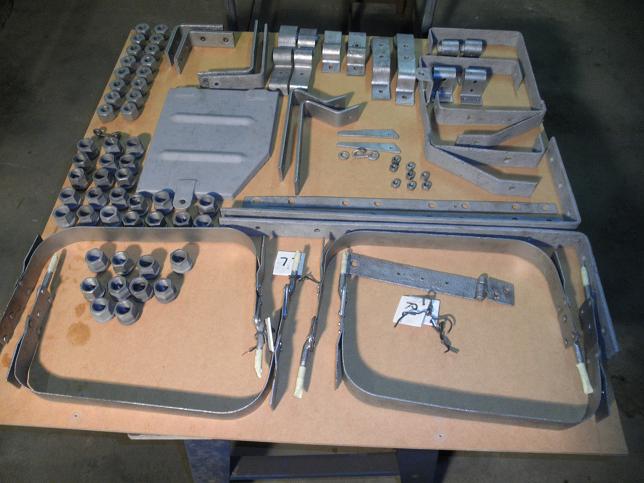


Petrol tanks cleaned with paint remover

Petrol tanks sprayed with primer and olive drab matt

New petrol tank supports

Satisfied with the work done!!!
Did not know but I probably have attached an images of the petrol tank how it was previously.


bedford mw square or hexagon nuts?
in British Vehicles
Posted
I'm using the "bedford authorised service parts catalogue (7/MW/PL9, dated June 1947) as a guide for my bedford mw restoration project. Striking in this catalogue is the listing of hexagon nuts for MWD body fixing.
In the catalogue only hexagon nuts are listed with all the carriage/coach bolts for front-, side- and tailboard fixing.
I was under the assumption that also square nuts are used, for instance, for tailboard fixing?
I know for sure the side boards are fixed with hexagon nuts. And how about the inside of the GS-body? I have square nuts inside as presented in the picture below.
So, according to the catalogue this is incorrect? I've seen other bedfords also having square nuts. One thing I'm sure, going through the catalogue, it will drive you nuts :nut:, but I still like to know the right application for the body! P.S. I have the side drop down version of the GS-body. Who has the knowledge?