


Danny P
-
Posts
299 -
Joined
-
Last visited
Content Type
Profiles
Forums
Gallery
Blogs
Events
Articles
Store
Downloads
Posts posted by Danny P
-
-
Hello Danny,
Nice work, did all this on mine, did you put grease between the leaves when you put the spring together?
Regards
John
Hi John,
I 've read a lot on the Forum wether there should be grease or not between the leafs. I think it will not harm especially because of the centre bolt and clips which will prevent slipping. I also ask Maurice who has a lot of experience in restoring wwii vehicles. He adviced me to use a little bit of copper grease between the leafs. So I used just a film of copper grease.
-
Next stage of my project:
Sand blasted wheel hubs and new oil seals placed
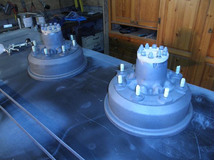
Finishing in olive drab matt

Rust removed from spring leafs (not sand blasted) and primed

Finishing in olive drab matt


Shock absorbers

Date of production April 1945
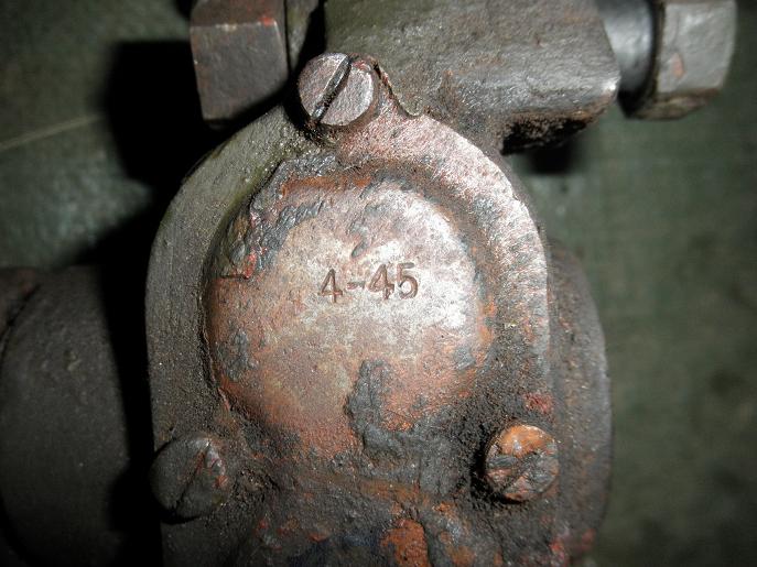
New hydraulic oil, gaskets en sprayed

Universal joint and flange of the bevel pinion

Sand blasting

Re-assembling

Next pictures to be expected: re-assembling of rear axle, springs and shock absorbers
-
Let's shake hands since I'm restoring a late bedford MWD at the moment! I hope we all can support you during the restoration through exchanging pictures, experiences and answers to the many questions that will come! I wish you good luck with the restoration project!
Danny
-
Production line of the carriers pitty its only 70 years ago and not in my garage
[ATTACH=CONFIG]74259[/ATTACH]
Look at that tower of four carriers! Apparently there were no safety procedures at that time?!
-
Finished making second dropside, and fitted the first one.
Looks like you're making progess on that body now! By the way, what wood did you use? Pine? I can see you treated the knots against falling out I guess? Is it just wood glue?
Good job, you're quicker then I am.:undecided:
-
Hi Danny,
Its good to see that you are putting so much effort in this lovely wee truck....
My Bedford heart is bounching faster now...
Its so much fun to drive these wee Bedfords.
Keep up the good work and post more photo's when ever you can.
Cheers,
Louis
p.s. what is your engine number..??
Hi Louis,
The engine number is 72177 and it is the original one as the number is also on the bulkhead.
Regards,
Danny
-
Nath
Just recently aquired an MWD, that needs some minor work and a general tidy up. But the canvas is well worn so I will be looking to have a full set made with a copola ring. Perhaps if there are a few of us after a set it may make it more worthwhile to produce.
Andy
Hi Andy,
I might also be interested in a full set for the MWD late version but a copola ring is not absolutely necessary to me! Curious what you can do!
Danny
-
Hi Danny
Nice restoration, as I can see on one of your pictures the Bedford has formation signs from the brigade Piron.
Has your MV served with this brigade are is it only because the last Belgian owner gave put these signs on.
Keep up the good work and on this forum you will find a lot of information.
Guy
Hi Guy,
I do not have any history about the bedford yet. Maybe someone recognizes the bedford. I bought it in Belgium so it could be that the previous owner has put the Brigade Piron on it. I think the bedford may also have run in Great Britain before since I noticed typical British flashers. So maybe someone (abroad) recognizes the vehicle????
I would like to trace the history or meet the previous owner(s)! Chassis number is 66674, shock absorbers are dated 4-45 and vehicle contract number is S8216.
-
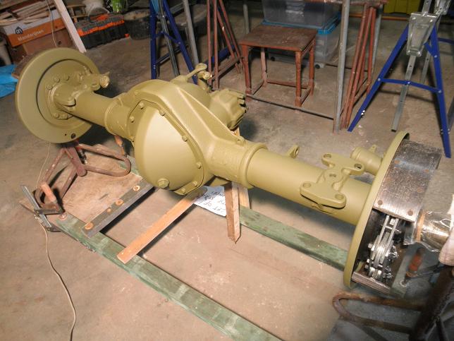
Rear axle olive drab matt

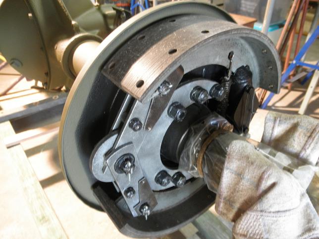
Differential

Flange plate

Brakes cleaned and reconditioned
Next pictures to be expected soon: hubs, springs and shock absorbers!
-
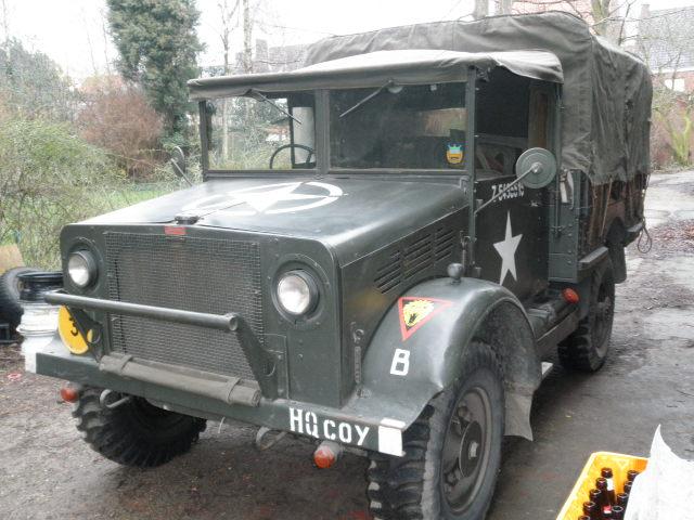
Some have already made acquaintance with me through the many questions I have asked all about bedford MW restoration. I 'm pleasantly surprised at the positive response and support from other vehicle owners. Many thanks to these people.
I now realize that I should return a favor by posting the first pictures of my Bedford MW restoration project.
As found in Belgium
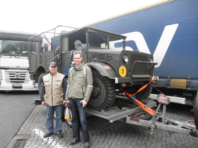
Transport to Maastricht The Netherlands (I'm the one on the right)
Body removed

Axle and paint removed

Starting removing rust
Primer sprayed on

Olive drab matt sprayed
Removing rust, primer and inspection of Rear axle


Next pictures are following soon!


-
Hello Danny,
I tried to get these parts from Norman aishe, But he didn't have any, and so far i am yet to see them on a bedford.
The way i have done it on my bedford is. I got a new front pipe from John Mortor. He said he had copied them from original parts. fitted the front pipe, them fitted a NOS silencer to it, them measured the gap between the bracket on the chassis and the one on the exhaust. It was around 3 inches, i made up a tube this length, and bolted it together with a castle nut. I left out the thackery washer as i didn't have one, but in light of the comment above i think i'll try and find one. Like yourself i'm a bit confused what the thackery washer will do, But it makes sense it need to flex.
John
Thanks John,
I found the following in a 1942 dated driver's handbook quoted:
The silencer is secured to the chassis frame by a single bracket. A spring washer is fitted between the nut and bracket. Use 7/16 SAE and 1/2 A/F open end spanners, but do not tighten unless loose.
There's also a figure in the handbook demonstrating the bolt and nut attachment of the silencer to the chassis bracket and it looks like the double spring washer is between the two brackets. So the bracket quoted must be the chassis bracket. But no distance piece! Furthermore the distance between the two brackets in the figure would then be maximum the size of the thackerey washer which is a flex of maybe half an inch. The distance piece stays a mysterie to me!
-
the distance peice is to get the correct tension on the thackery washer this allows the silencer to twist in relation to the chassis mounted bracket.
I don't get it! The bolt plus flat washer is going through the bracket, then the thackery washer is going over the bolt, then the silencer en finally the lock washer with the nut. I assume the distance piece is a hollow tube which is also placed over the bolt? I can not think of a construction to get a tension with the thackery washer. It must be easy, but maybe I don't have my day today! Can you or someone explain please?
-
According to the Bedford authorised service parts list the exhaust silencer is attached to the chassis support bracket using the following fasteners:
• bolt, special, silencer to support bracket
• washer steel, 5/16" small flat, silencer to support bracket bolt
• washer, thackray (double spring washer), 7/16" silencer to support bracket bolt
• nut, hex. slotted, 5/16"-24, silencer to support bracket bolt
• distance piece, silencer to support bracket
Questions:
- What kind of bolt is used? What is special about it?
- Is it a brass bolt and brass nut?
- Where is the distance piece for? What are the dimensions and how is it attached?
-
While wandering around the Spartan at the weekend deciding where to start, I convinced myself to take advantage of the fact the vehicle is already half stripped and get stuff like shotblasting out of the way first. Don't want grit getting all in my repaired electrics and engine etc..
What sort of prices have people paid for mobile shotblasters to do a (CVRT sized) vehicle?
I'm toying with trying to save money and do it myself. I can borrow a 5/6hp petrol compressor and a hand held shotblasting gun from the usual suspects are only about £20/30.. obviously I'd still need the blasting media and a respirator but I'll need that for respraying anyway.
Has anyone got any advice/experience on this or is this one of those jobs thats just better left to someone else?
Cheers,
James
You'd better do it yourself by hiring a sanblast cabin the size of a garage for the big parts and ask friends or your employer for the smaller parts. Especially the smaller parts will be time-consuming and as you know time is money. So, it will be a way of choosing the middle of costs but you will be satisfied at the end. Besides, you don't have to clean all the mess at home! Look before you leap!:cool2:
-
Hi Danny, sorry about the delay in replying. I have rebuilt my cross members by copying the remains of the originals, but I dont have any mudguards to refer to so will make them to fit. There does appear to be differences in body construction from the little I have seen. Rippo is really the man to ask, maybe he'll be along here soon!
In the mean time I have continued with the body sides. I could not find any suitable hinges anywhere so have fabricated some, hope they dont look too bad and will pass muster! One dropside now has the metal edging all the way round.
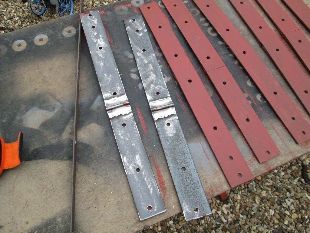
I like your creativity for the hinges. Maybe you should round the corners a little bit like the originals? It is a good alternative to progress your project. There may be an oppertunity in the future to exchange them by the originals if necessary. Fairly an easy job to do I think!
-
Hello
Coming together nicely paul.
I'm not to sure what danny is asking, can you put some pictures up?
I already wrote a draft version for a new post but lets just put it on here!
I‘ve got a question about the GS body and framework of my Bedford MW!
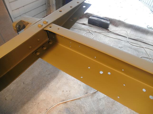
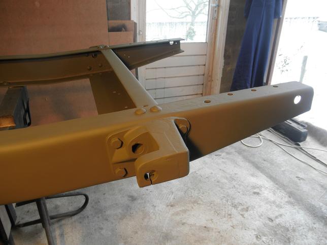
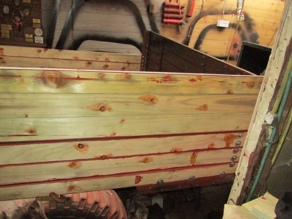
I’m not sure about the dimensions of the beveled sides of the beams towards the mud flaps are attached. I’ve seen some pictures of other restorations which I’ve enclosed to explain my question.
In the first picture below you can see a red line and circle I’ve drawn. With this line and circle you can see that the end of the short beam, above the rear axle, is not in line with the beginning of the beveled side for the mud flaps on the other beam. Is this correct?
To be correct in the first place, when attaching the mud flaps they will closely fit the total width of the beveled side of the beam and will even extend outwards the frame so that they will be in line with the outside of the side boards.

(double click on the image for enlarging)
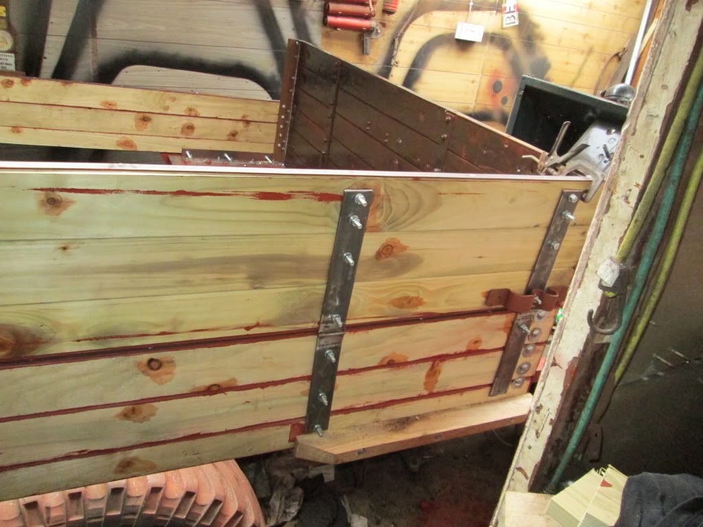
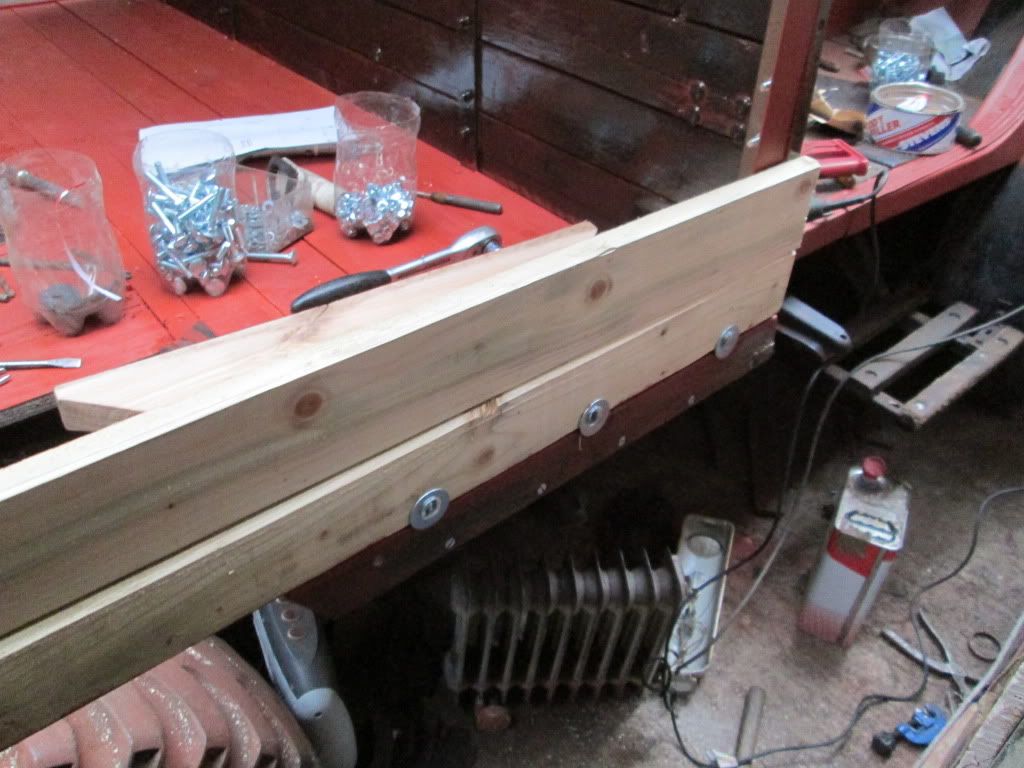
The next picture is the wooden framework of my Bedford. Again I’ve drawn a red circle at the same location as the circle in the first picture. Both locations look similar to me. I’ve also drawn a dotted line at the location of the wooden wheel box.

Subsequently the inside of the wooden wheel boxes are covered with one big iron plate 90° angled and two small iron plates which are having a small edge 90° angled on two sides as presented in the next two pictures.

As you can see in the pictures the small iron side plates are having a big chamfer flap on the overall width which will fit the beveled side of the beam where also the mud flaps are located (double covering). Is this correct?
The next problem will occur when fitting the total wooden box on the frame.

The box will not fit the dotted line of my second picture, due to the chamfer flaps which will closely fit the beveled sides. As far as I know, the centre beam above the rear axle should end in line with the inside of the wheel box and should not end somewhere under the floor.
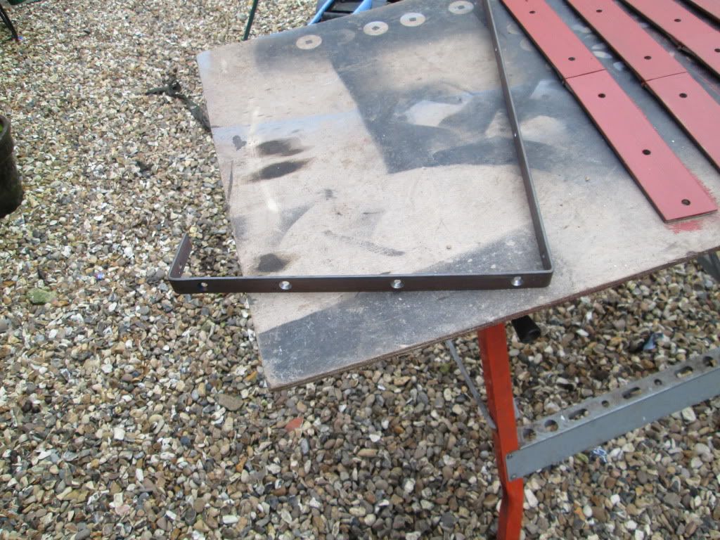
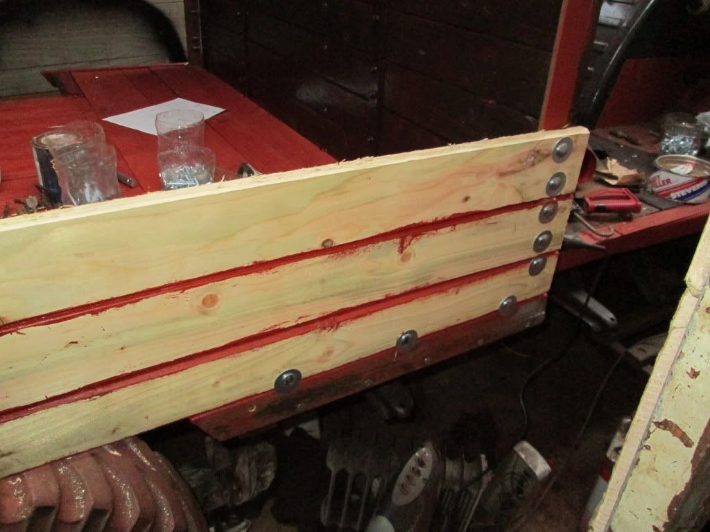
Finally a picture of my own wheel box upside down. You can see there are no chamfer flaps. The side plates are just about half an inch to one inch below the wood

At first sight it all looks OK but studying these pictures there is something strange or is it that I do not understand the construction?
Can anyone help on this or reply with some pictures from a same location (inner side of the wheel box)?


-
Hello Danny,
I used rubber strips on my truck. I have a couple of old petrol tanks and there is bits of rubber on them. Also cotton will hold water against the petrol tank. If the straps are trimmed nicely, once the petrol tanks are fitted the straps can not be seen.
Regards
john
That will also be a good advice, thanks!
-
Soak the end in a greasy glue such as Areldite. best to get some proper metal end clips and afix those. If they are cotton it is worth soaking them in something like Nikwax cotton proof, stops them absorbing water.
Thanks to all
-
Hello Danny,
These bolts nearly always strip the thread as the manual says to peen the end of the bolt when assembling. I got mine from the local engineers supplies 3/8 UNF, if your struggling i can get some and send them to you at cost.
Regards
John
I've sent you a private message :laugh:!
-
I want to use the webbing in below picture for attaching the petrol tanks to the brackets. Therefore I have to cut the roll into pieces. I've tried to melt the ends to prevent fraying but it is 100% cotton. Do I need to sew it or can I use a suitable glue?

-
I'm looking for 8 original spring leaf clip bolts or good alternatives for my Bedford MW (4 on each side). They are 3/8-24TPI and 3 or 3.1 inches length. The alternatives must be at least grade 8 or higher. Can someone help on this please!

Thanks,
Danny P
-
I have started building up the body sides, but owing to wife's slipped disc have had few other jobs and errands this weekend!
Nice to see that someone is also reconstructing the body. I have a question about that. If I look at your picture of the floor you can see the wooden beam in the center just behind the wheel. To the left and right of this beam we have the beams to which the mudguards are attached. I can see at yours that the bevelled edge of these beams are ending equal to the end of that center beam. I assume that, when attaching the mudguards to the bevelled edges, they will closely fit towards the inside ends of these bevelled edges. Subsequently, having the correct mudguards, this will imply that the mudguards will protude aside from the floor. And that's correct. Because, when finishing the body, the sides of the mudguards will run in line with the side boards.
I had to reconstruct the beams with the bevelled edges at my bedford with the assumption that the mudguards should closely fit towards the inside ends of the bevelled edges as described above. But when I placed my mudguards they were about 1-1.5 inches away from the end of the bevelled edge. Does this mean that my mudguards are too small or do they not closely fit towards the end of the bevelled edges? What should be the width of the mudguards then? Maybe I have some mudguards from another British wwii vehicle?
Could you help me on this, or anyone else?
Danny P
-
My truck is chassis number 18073 (chassis numbers seem all over the place!?) Contract T8957 MW. I also have a number stamped in one of the original body bits, 14198 - any ideas?
I need a brass plate for the body side and the Bedford chassis number plate for the dash if any one has such things or knows of anyone reproducing them?
So this is a 1940 dated truck according to Richard Farrants list. Typical that the contract number of this early bedford is at the end of the service parts list. My approach that the contract numbers would be in a chronological order is then totally misplaced!:-D
Danny P
-
What Danny has got on information is not entirely correct , In the files wich Bart Vanderveen had ( in his Bedford book he also made a short list with numbers and for ease said first delivered in 1940), it started at chassis 1001, and in sept 39 the first contract for 50 MW for AA service were delivered , from there there were 2 more contracts , one which was finalized in 1940. Easy way so see 3rd batch is the fitment of double working shock absorbers , and beefed up military step brackets . first 2 batches had the pre war civy step brackets.
Hello Maurice,
Are you refering to the chassis numbers vs. production dates or my approach regarding the chronological order of the contract numbers in the parts list?
Regards,
Danny P


Bedford MW restoration project 2012/2013
in Blogs of MV restorations
Posted
John,
That's the reason why I chose for copper grease, to prevent long term attraction of dust, sand and dirt sticking to the grease with the risk of sanding your leafs!