


Old Bill
-
Posts
1,661 -
Joined
-
Last visited
-
Days Won
33
Content Type
Profiles
Forums
Gallery
Blogs
Events
Articles
Store
Downloads
Everything posted by Old Bill
-
Hi Andy. It was PTFE which started me on the cork trail in the first place! Sarah, one of the Jezebel crew, kindly pointed out that PTFE swells in petrol which is why the original tap jammed up. I am hoping still to be able to open it when we go to recover the Dennis from storage prior to the Brighton run. Steve
-
Ok, I will make a point of it. The thought of losing 30 gallons of fuel in the road rather frightens me! I also have in stock, an ordinary old fashioned cork cut from a single piece. I think I will try making one up from that whilst I still have the procedure in mind and the tools on the bench. Steve
-
Good thinking! I will go and syphon some petrol. Yesterday, I carried on and finished the tap. First, I turned up two sleeves with a 5/8" BSF thread. Then I turned the old thread off. Silver soldered the sleeves. A good clean up and it is ready to fit (pending cork trials of course!)


-
Lovely job! These things really finish a project off. Steve
-
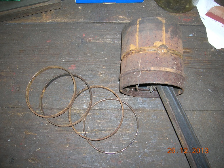
With Brighton getting close again, I thought it was time I did some work on our own lorry! I have, therefore, been looking at the fuel tap issue once again. Whilst rummaging in a box of bits, I found this tap which I had forgotten about. It was obviously designed for a cork sleeve but this is missing so my thoughts turned once again to the challenge of machining cork. I found a cork which I held gently in the three-jaw and drilled through at 3/8" diameter, very gently at high speed. This was successful. The outside diameter presented more of a challenge.Many years ago, a dear friend had suggested that cork and rubber could be machined using a grinding process. I therefore set my Dremel pencil grinder up in the toolpost of the lathe with a grinding disc and pushed the cork sleeve onto a piece of bar held in the chuck. With the lathe running at 300 rpm and taking 0.005" cuts, I ground the surface with this result. It quickly became apparent that some dust extraction might be advisable! I did try heavier cuts but the wheel soon clogged so I stuck with five thou until the body of the tap pushed on. After removing the sleeve, I cut a couple of notches with the Stanly knife to engage with the drive dogs and then assembled with a drop of oil. A quick poke through with a drill to give the 'open' position and Bingo! The task for this morning is to put the correct threads on the tap to suit the lorry. One question remains, however. The cork is reconstituted crumb so will it survive without breaking up? I know it is alcohol resistant (!) but what about petrol? No doubt we will find out in due course! Steve


-
The Subsidy scheme was introduced to try to provide the military with a group of similar lorries and reduce the need for spares. Unfortunately, the war started before it really got going so there was a very small pool for the government to pull from. Various items were standardised such as wheel bearings, tyre sizes (881x120 on the rear and 720x120 on the front) and control positions. Interestingly, the Thornycroft has grease lubrication at the hubs but the Dennis specifies oil. 'Oil' is even stamped into the fill plugs in the hub caps. Whilst I think that oil is the better solution, there are no seals of any sort so the oil runs from the hub cap, straight through the bearing and down the inside of the wheel. We are OK at the moment as the bearings are new but once a bit of wear builds up, I can't imagine it staying in the hub for very long! Steve
-
Hi Will. They won't have been tapered bushes here as part of the 1912 Subvention Scheme specified the size of the wheel bearings, amongst other things. They are plain parallel bronze and fully floating with flat thrust washers at the inner end. Dennis used the same system as their 'Subsidy A' was also an approved vehicle. Ours actually runs on Thornycroft bearings at the rear as the ones we had were the best fit! I too am surprised at the amount of wear in the front wheels but have yet to inspect them. We are going to Devon shortly to pull the Dennis out of storage ready for Brighton so I shall take a look then. It may well be that we have to have them skimmed out and make over-sized bushes to suit but fortunately, I know a man who can do that! The joint in the wheel is a perfect rust trap and I don't know why this new pair have survived so well. There may be a bead there but I should be very surprised if there is. Most companies used spoked wheels but I wonder whether there was a problem in getting these big castings so Thornycroft went for the plate construction. We will never know now, I guess. I understand that the plate wheels were made for Thornycrofts by Taskers at Andover. Brighton is getting close now so it is time I did some more Dennis. Steve:-)
-
Hi Dan. As Andy says, I would ignore it! Our FWD also has three cracks just like that. They don't leak when parked but are inclined to weep when the engine is running. They are an annoyance but don't stop us running and I think the risk of doing more damage trying to fix them is quite high. Leave it alone and see what happens! Steve
-
Hi KAGA. The answer is that you talk to people and join a forum like this! Please will you start a thread to tell us about your FWD as we are all keen to see it. We (Great War Truck aka 'Tim', Father and I) have such a beast which we did fifteen years ago and have taken lots of photos through the rebuild process. I also have a photocopy of the original US Army manual which is truly outstanding and can copy that for you as well. Let us know what you are up to and what you need and we will do our best to help out. Which part of the world are you in? Good luck with it! Steve
-
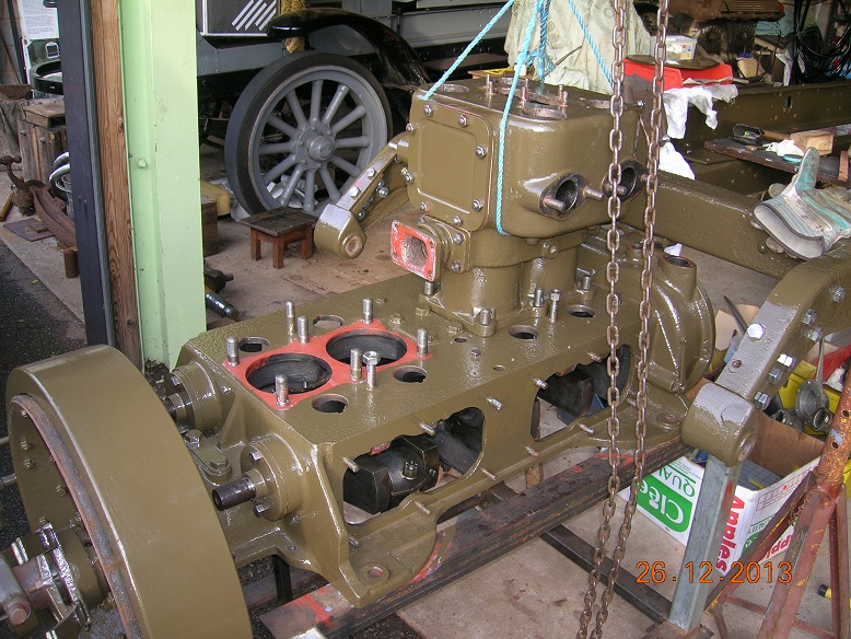
The Museum has now confirmed that the Maudslay has been entered for the London to Brighton run this May. It is now all hands to the pumps! The hood bow hinges were drilled for screws and filed to remove the sharp edges. A polish with the flap wheel finished them off. Then the special pivot bolts were fabricated using silver solder. And the complete set of parts were laid out for a photo. They were mounted on the seat box yesterday to confirm the heights and the hood bows will be fitted to them this week, ready for the canvas man to make the hood. This is the last major part outside of the direct control of the Team so the sooner the bows are away, the better. The steering wheel continues. As you can see, it is too big for my mill to be able to face the boss so a mate in Taunton very kindly allowed me to use his. The wheel is now with one of the TEam for polishing before sending to the powder coater. The bonnet has broken hinges and only one handle so I have made up some new ones. This is the pattern: First, I made a plasticard template and filed out four blanks. The arms were than dished by tapping them into a curved groove cut into the top of a piece of MDF. The main shape was dished by beating on a leather sand bag with a bossing mallet. The edges were tapped over a stake before polishing. Two replacement bonnet hinges were fabricated using my favourite silver solder. The engine is now in as you can see from this terrible picture. Quite a lot of work is still needed to connect it to the rest of the vehicle, however! The body mounting brackets arrived this week as well. They have been made by a local fabricator and have come out rather well, needing only a little tidying up and filling around the welds. Still a lot to do but I will keep you posted! Steve :-)


-
Hi there! Yes, progress has been a bit slow recently. This having to earn a living really gets in the way! For the last twenty years or so, I have managed around 360 hours per year working on my various projects ( I have a chart in my workshop; sad git!). Last year, it dropped off to only 220 for a variety of reasons and this has slowed things down. I am also giving a few hours to the Maudslay project at the moment to get the thing ready for the Brighton run this year. That is going to be another last minute dash but we should do it, even if not complete in every detail. I will post a few pics of that later too. How many hours do you chaps devote to your projects? More later! Steve
-
Interesting collection. Not quite enough of the lorry to identify. I wonder how many more collections like this there still are around the country? Steve
-
I would agree with Richards postulation that it is American. That primer is identical to those in our American built Autocars. I am pleased to learn of 'Park Drop Forgings' though. Something else to look out for! Steve :-D
-
I have been doing a bit of blacksmithing today, by bending the steel parts of the hood bow frame. These are simple flat strips but have the ends curved upwards and a joggle to dodge the vertical parts of the frame when the wooden bows are the same width. I am a very inexperienced blacksmith so the quality of work is nothing special and will require a lot of cleaning up to hide the hammer marks but they should do the job. The process starts with the lighting of my home-made firepot. This is fed by the fan from my dust extractor. Then knock the curve over the beak: Flatten it out. Bend the first part of the joggle one way. And turn it over to bend it back. Repeat for the opposite hand and there are two hood bow irons. No time at all to bend but a lot of hours still needed to clean up and finish! Steve :-)


-
Hi Will. Many thanks for your kind comments. It is wonderful for us to be able to share our pastime with so many friends we have never met. We have had so much advice and encouragement and it is most gratifying to think we can encourage someone else in their project. I am convinced that anyone can do this sort of thing, though. You just have to want to do it! Good luck with the three wheeler! Steve :-)
-
Thanks Matt. I'm glad you haven't got bored with it yet! Perhaps we will meet on Brighton seafront again next year. We are hoping for nine Great War vehicles this time so it should be worth seeing! Steve. :-)
-
I'm sure that would be fine but I don't want to part with anything until we have completed the job. I have been caught that way before! Keep in touch! Steve :-)
-
Everything we take off is kept until the end. Real scrap, bushes and pins and such like will be binned but the old pistons will be labelled and boxed and go into store. Silly really but they might be useful to somebody one day. Steve :-)
-
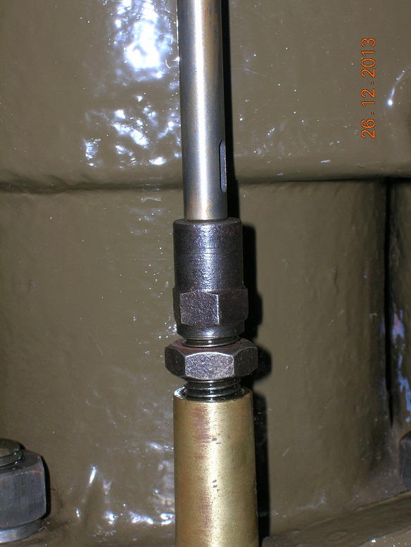
One thing the lorry is short of is a proper period steering wheel. The one it has, has been 'adapted' but does not fit very well and looks too new. From the best pictures we can find and looking at other Maudslays in the museum, it appears to be remarkably similar to the one we should have on our Thornycroft so Father had two castings made with one allocated to the Maudslay. To attach it, I have made a 3/4" BSP nut and spigot to be attached to the column. Today, I set the wheel up on the faceplate and bored it through to fit the spigot which has a 4.5° incl taper and a keyway. I had the spigot available to try in the hole in order to get the depth right and allow some space for the nut to pull up. Finally, I cut the keyway using a boring bar with the bit ground to suit the slot and planed it out by winding the carriage back and forth. It was a bit laborious but effective. Once I have faced the front, I shall present the wheel to the volunteers for someone else to polish the casting! Steve :-)


-
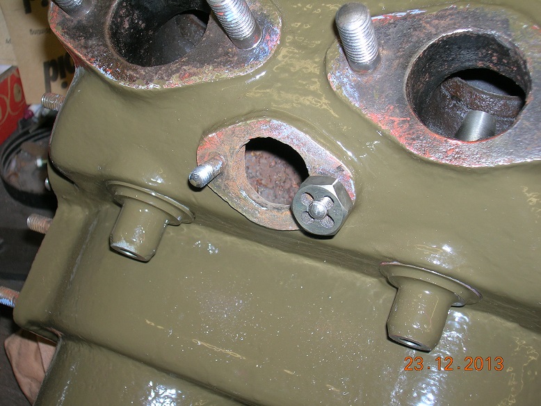
Hi Andy. No, we haven't fitted a gasket under the block. We had some debate about it but as there was none there when we took it apart and it isn't mentioned in the parts book, we decided not to. It would, however, have helped with the tappet clearance! Steve :-)
-
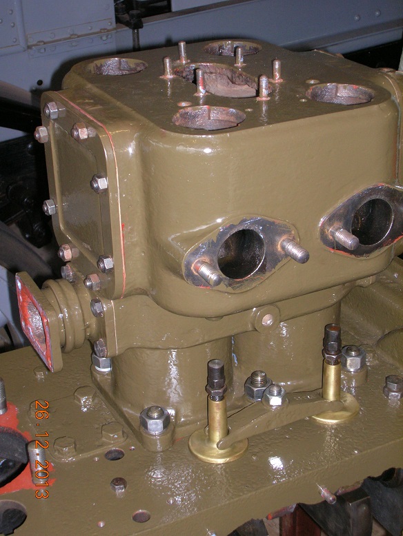
We started today where we left off yesterday by fitting another piston to number two rod, securing it with the spring clip without breaking it and then by fitting the remaining rings. This all went well and the rod was bolted to the crank and tightened right up. This showed the bearing to still be a little tight but a couple of scrapes soon sorted it and the nuts were secured with split pins. Two rods down. A brief intermission was taken to salvage four spring clips from the other pistons ready for cleaning up and reducing in size to fit the smaller pistons. That achieved, we decided to fit one block to protect the rings and see how it all looked. The chain block was used to raise it and the engine was wheeled underneath. After wiping the bore and pistons with an oily rag, Dad slowly lowered the block whilst I poked the rings in with a piece of wood and a screwdriver. I remembered from the Dennis that pushing the rings with ones finger tips is not a good idea as the block can suddenly drop, trimming one's finger nail, if not more! Once fully down, the block was held with 5/8" nuts on the new studs made earlier. The cam followers were also fitted and clamped down. At this point, I wanted to grind the valves in but was dismayed to find that our re-cut valve seats have dropped so far that there is no longer any tappet clearance. I need to find about 0.060" and propose doing this by trimming the end of the valves and possibly facing a little from the tappet. I would prefer to trim only the tappet but there is just not enough metal there. Another challenge to be overcome! Steve


-
After fitting all the gaskets and covers, the next step has been to 'gap the rings'. The rings we have are for 110mm bore which is slightly bigger than the 4 5/16" of our liners so I have dressed the ends back to give a clearance between them of 0.012". A gap of 0.002-0.003" per inch of bore is recommended on the scraper ring packaging so I have simply followed that. Unfortunately, after completing fifteen rings, I had a disappointment when I found that the last scraper ring was too small and already had a gap of about 3/8". All of the packets were correctly marked but one is undersize. I shall have to contact the supplier in the New Year but it is a bit of a disappointment as we cannot do much more to the engine. I can do a bit though so I have fitted the first piston to a rod by pushing the gudgeon pin into the newly honed bore. It went beautifully and I had then only to fit the re-sized spring clip to secure it Disaster! I have obviously not got my heat treatment quite right and two of the clips broke in my hands. Closer inspection revealed cracks at the breaks but it was most annoying. I softened the two remaining clips a bit further and my third attempt at fitting one was successful and worked a treat. Then the other rings were fitted uneventfully and the rod was ready for the engine. When fully torqued, the bearing was a bit tight but another blue and scrape sorted that and the rod is now secured and pinned. I will try to do another tomorrow and perhaps we can at least get the front block fitted. Steve :-)


-
Thanks Chris. That is a very good piece of guidance. I'm just going out to scrape a little more as I have torqued up the first big end completely and it is just a little too tight. More later. Happy Christmas everyone! Steve:)
-
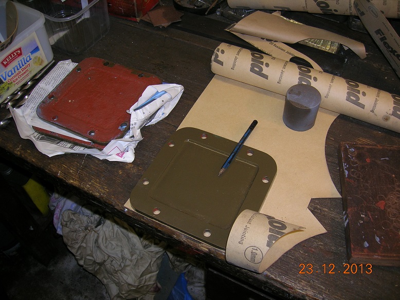
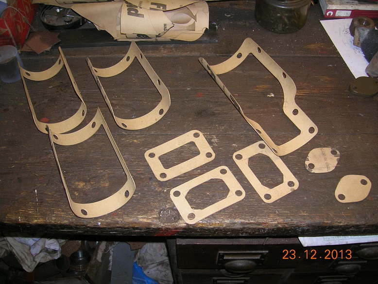
Next part of the job is to assemble the blocks. Firstly, all of the necessary gaskets were marked out and cut using a pencil, rule, Stanley knife and wad punches Then the threads were cleaned up with a die nut before fitting the first cover. As the mating surfaces were so poor, red Hermetite was used to help the seal. Then all of the other covers were fitted including the pump mounting casting. This has proven to be more than a day's work but the results are quite pleasing. The next task is to gap and fit the rings before permanently setting up the rods on the crank. Plenty to do tomorrow!


-
Thanks Richard. That's an interesting item I have not come across before. Should the rods fall around the crank when fully tight or should there be some resistance? At the moment, I have two which fall freely and two which require a slight push. What I really need is to see an expert do it and then feel for myself! Steve.


