


Old Bill
-
Posts
1,664 -
Joined
-
Last visited
-
Days Won
33
Content Type
Profiles
Forums
Gallery
Blogs
Events
Articles
Store
Downloads
Everything posted by Old Bill
-
Thinking a bit more about the track rod, the ball joints would benefit from hardening. The originals were not very hard but that might have been because the surface had corroded away. Anyway, I decided to case harden the new ball joints. First step is to heat them to a bright red using the propane torch. Sorry, you can't see the glow but I ran out of hands at that point! Once red, they were stood in a tin of case hardening compound, known as 'Kasenit'. This is a grey powder, very high in carbon. The carbon soaks into the surface of the steel locally converting it to a 'high carbon' steel which can be hardened. The balls were then re-heated to bright red before quenching in cold water. They look quite rough at this stage but a stiff wire brushing soon cleans them up Track rod next. Steve (Trying to keep up with that Human Dynamo, Ben!)


-
Why are you interested in Cohendet? It is a pretty obscure make to pick on! Steve
-
What do you do in your spare time, Ben? Amazing progress. You put us to shame and there are three of us! Steve
-
Sorry Barry, you will have to wait a bit longer. Too much going on here. Earning a living gets in the way too! Steve
-
Thanks John. That one is excellent. It seems that the secret of getting the job off is to have a highly polished, metal mandrel, I am amazed at how far he spins it without annealing in between. I would have treated it at least half a dozen times. Not brave enough I guess! The job will have to wait now until I am in Devon again to use the Colchester. It is a bit big and brutal for the poor old Myford! Steve
-
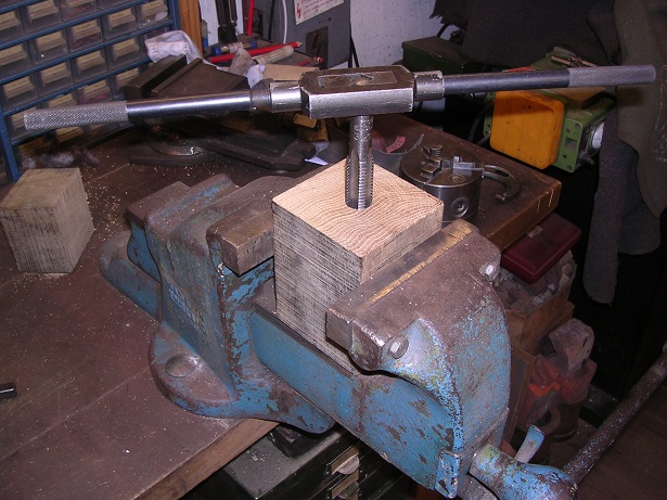
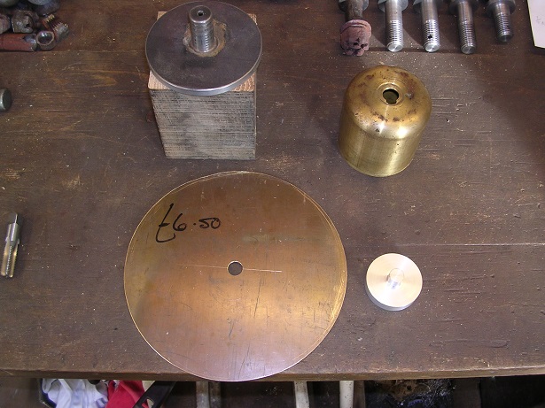
I have been preparing for the spinning exercise today. I had a rummage under the bench and came up with a splendid piece of oak which has been there for twenty years. It is hard as hell! This is good as when I have spun onto softer material, it has come out with a wood grain finish. This was faced off, drilled and then tapped 3/4" BSW to suit my back plate which I hold in the chuck. The next pice was the follower. This is a plate the diameter of the flat part of the cover with a central spigot to locate the disc. It is clamped up by using the revolving centre in the tailstock pushed into the centre on the reverse side. Then it was time to cut out the blank. Our local second hand tool shop had a piece of brass in stock, big enough to make two, just in case I make a mess of the first one. It was roughed out with the nibbler and then filed all round to make a smooth edge. I think that this makes the edge a lot easier to finish and removes any stress concentrators reducing the chances of cracking starting around the edge. That finished the spinning preparations. Further progress will have to wait until I can use Father's Colchester again. Finally today, I turned up the mounting adaptors to attach the cover to the top of the king pin and give a tapped hole for the stauffer. We are getting close to being able to hang the front wheels now, the next big milestone!


-
Yes, that could certainly be done although I have never tried it. It does depend on getting the right size tube to start with, though. I would have to have a few goes to judge the tube length as well. Another possibility. Thanks!
-
Don't worry. You certainly put me to shame! Steve
-
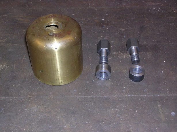
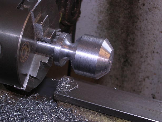
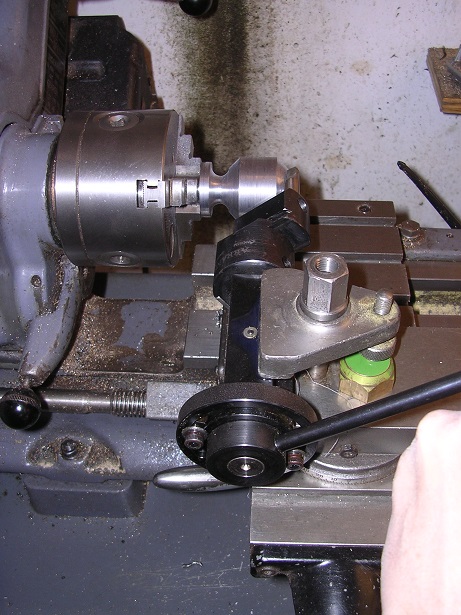
I shall do some spinning preparation tomorrow. In the mean time, I have been making track rod ball ends. Initially, I was hopeful that we could salvage the original ball ends but closer inspection revealed them to be pretty sick. The only solution was to make up some more. Fortunately, the originals were not hardened at all so it started off as a simple turning job in medium carbon steel. Dad did the donkey work, turning the shanks and screw cutting the 3/4" BSW threads. I then put them in the Myford and turned them roughly ball shaped. I now had the puzzle of generating a ball shape reasonably accurately. I did consider my spherical milling approach, previously seen in these pages but felt that a better approach might be to use a ball-turning attachment. I therefore acquired one from Arrand Engineering. It requires a boring head to be mounted on the end to carry the tool but I found that mine doesn't fit! Fortunately, I was able to borrow Father's, also made by Arrand. The boring head simply unscrews from the taper shank and then onto the turning attachment which is mounted in the toolpost. The tool is controlled by moving the lever in the foreground, gently and smoothly. I did have some trouble though as I had ground the tool with a standard knife edge. The turning attachment is meant for model engineers and balls of about 1/2" diameter so my 1 5/8" ones were stretching it to the limit. As a result, it was all flexing a little bit and the knife edge on the tool tended to drag it in to a deeper cut before springing out leaving a series of steps. I was at a loss to know what to do about this until I ran the tool backward with the knife edge trailing. It then gave a nice consistent smooth cut at a depth of 0.005". This was slow but quite satisfactory considering what I was expecting it to do. I left 0.002" on for a final polish with emery and they came out well. Now I must ovehaul the female sections to match!


-
All done in one go? What sort of speed? Steve
-
They look fine, Andy. What speed did you use and what sort of tool? I have used a bronze tool on steel in the past because my lovely hardened steel tools were ruined in no short order! Did you do them in one go or did you heat them part way through to reduce the cracking?
-
Thanks Andy. Yes, that's a good one. There are several on Youtube and I have bought a DVD from this bloke as well. Sometimes, though, you just want to talk to someone! The trouble with these old lorries is that you need so many skills and it is very hard to obtain them all. Never mind. One at a time!
-
Thanks Steve. You certainly have helped me out. My spinning has come about by buying a book, making some tools and having a go. I have never been able to speak with anyone who actually knows what they are talking about on the subject! I always put a hole in the centre if I can so that I can have a locating pin as I am concerned about the disc flying out at the start of the job. Incidentally, please may I have some guidance on speeds? This one will be brass, 16swg and the initial diameter of the disc will be 8". My book says 'fast' but I don't know what that really means. I feel inclined to try about 400rpm but I would value some guidance please. Cheers! Steve
-
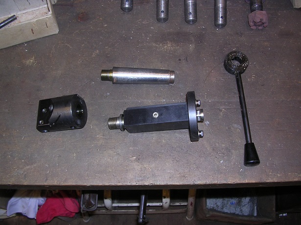
We did do a little more over the weekend. First thing was to fit the governor casting (without butterfly!). Of course, it needs some linkage. I had a rummage around and found some ball joints that we had bought years ago. They were just right! A quick clean up and a rod and the effect is complete. Finally, we made up the starting dog and fitted it to the end of the crank. A couple more bits done. Must press on with the front axle now as we really want to get it on its wheels.


-
For just one-off, I will start with this approach. It is nice to know, however, that there are a few more strings to my bow if need be! Many thanks!
-
That is still only a factor of three! Full size locomotive boilers are designed with a factor of five and our models run at eight! Fascinating clip though. Steve
-
Thanks Steve. It sounds like I should be making a metal chuck/mandrel so that it doesn't get a grip. I hadn't thought of drilling the middle though. I will put a hole in the centre of my blank so that I can have a locating peg to prevent the unformed disc from flying out at speed. That might prove more excitement than I want! Steve
-
Deep drawing would work. The challenge for me is to make the part with a minimum of tooling as I only want one! Worth keeping up my sleeve. Thanks for the fascinating clip! Steve
-
Wonderful! You can learn something new every day! Thanks!
-
Hi Hedd. It is 3 3/16" dia by 3 3/16" long and 16swg. It is going to take some pushing around which is very unkind to lathes! Steve
-
Rollforming sounds interesting. How would that work? I think of it as a progressive folding process for producing long, two dimensional sections such as gutters and haven't seen it produce cylindrical items. I'll try anything which gives me the results I want! Yes, annealing is essential and if anything, I do it too much. In the clip above (Thanks Chopa!) the spinner carries out a tremendous amount of forming in one hit whereas I tend to remove the part, re-anneal it and then put it back for another go. My concern about getting the piece off the mandrel is that I want to remove it, anneal it and put it back a number of times. The difficulty is that it is parallel and has to slide the whole way along the mandrel. The split mandrel in the clip above is tapered two ways so once loosened, the part comes off. I could make the mandrel out of aluminium which would prevent the brass from getting a grip but I don't want to go to that much trouble. A nice piece of oak or mahogany will do the job well, as long as I can get the thing off! Waxing the block and then gently warming the brass sounds like quite a nice approach. Incidentally, what is 'Spelching'. I've not heard that one before and my dictionary isn't being very helpful either! Cheers! Steve
-
Thanks Jake. I must admit that it desn't look a good solution. It is how they were made though so I must try it first. The worst that could happen is that the nut backs off and takes the load off the ball race making the steering very stiff so I should soon notice it! No doubt time will tell. Very pleased to hear that you are enjoying this. It is the only reason for doing it after all! Steve
-
That is a good thought and should work well on a wooden former. I'll try it! Steve
-
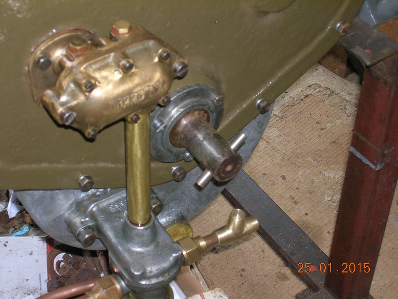
Hi Ian. This lorry, like so many others of the period, had a speed-limiting governor. With experienced drivers so rare at this time, there was a tendency to see how fast the vehicle would go by holding the foot down until something broke! Governors were fitted to prevent this and should limit the vehicle to about 14mph. Our engine was missing the governor so we made up a replacement (page 61 onwards). It works by bob-weights swinging out against springs and actuating a butterfly in the inlet manifold to throttle the mixture and limit the speed. From a driving point of view, I don't want that function. It's bad enough driving in modern traffic without sudden unexpected reductions in power output so we have put everything back just to make it look right. If some future owner, many years hence, wishes to have it, the butterfly can simply be fitted once again. Cheers! Steve
-
I think that is the most likely reason. The grease would come out the sides as the stauffer was screwed down. On that front, I shall screw in a Tecalemit grease point and prime it with a gun before fitting the stauffer. Much less messy! Steve


