


Old Bill
-
Posts
1,669 -
Joined
-
Last visited
-
Days Won
33
Content Type
Profiles
Forums
Gallery
Blogs
Events
Articles
Store
Downloads
Posts posted by Old Bill
-
-
Many thanks for the links. Unfortunately, they all have double coil spring locking washers rather than the Thackery anti-rattle washers so they are shaped to bit in rather than just fill the space. One has some Thackery washers but they are all small and used predominently for carburettors.
Thanks for the suggestions though.
We will keep looking!
Steve :-)
-
That's interesting. Several of the old Thornycroft machine tools ended up with the Hampshire County Council Museums Service and were used in their workshops when I volunteered there years ago. The HSE visited and had a fit which we thought was very unfair. Everything was appropriately guarded. The tools were just very old and were built with a different mindset from today. Oh well. Happy days.
Steve

-
Well, the ambulance is a Renault but the one showing battle damage, I am pretty sure, is not as there is no sign of the scuttle mounted radiator. It does look like a big staff car.
I shall await some input from the Gurus now!
Steve
-
We are generally pushing on with the controls now. Dad has picked up the castings for the quadrants but, amazingly, hasn't taken any photos of them! He did take a picture of the laser cut handbrake ratchet which has saved a lot of hand work.

He has also been painting some of the gear lever parts as well.

He has started to clean up the gear change quadrant. It still needs a good bit of filing due to the shortcomings in the pattern and the reverse stop needs some adjustment to suit the lever. Once this is done, it will be ready for engraving with the gear numbers.


He has drilled the bolt holes and also those for the handbrake quadrant. It is beginning to look quite good.


Of course, it needs a handbrake lever to fit. The one we have was very corroded around the quadrant and also bent. The press more or less sorted the bend out and our good friend Adrian, kindly built up the wasting with weld.

This has been dressed back and filled but requires a final tweak to the bend to make sure that it fits between the quadrants before final painting.


No pawl has survived so I have machined one up copying a very corroded one that we have.


I have also made a new pull-rod but cannot set the position of the pawl until it is trial-fitted, the next time in Devon.

Two new pivot pins have been turned up, 1/32" oversize to accommodate most of the wear, but the copper rivets are just dropped into the holes for trial purposes.

Finally, Father has turned up a new throttle pedal face.

I am giving the pedal shaft some attention at the moment but thoughts will shortly be turning towards the steering column. Always something to do!
Steve
-
I have just undertaken a minor modification. The throttle pedal as built is too high and is crippling on th ankle after a couple of hours so I have taken a leaf out of a very old book and fitted a heel block.

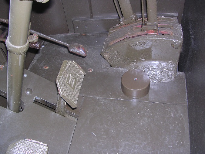
Nothing very clever but it should be more comfortable to drive next year!
Steve
-
Thanks Richard. These are actually double coil spring washers so the ends point upwards to dig into the nut. The Thackery washer is more of a flat spring to stop rattle. I have a few friends rummaging in their 'useful bits' boxes at the moment and we are hopeful of finding the remaining three.
Sorry for the scant postings recently. Normal service should now be resumed! Here is something to be going on with.
When I saw the broken engine at Old Warden in September, I spotted this wick-feed oil cup on top of the magneto drive. Well, that answered a question for me as to what went into the hole in ours!

Dad went to Beaulieu Autojumble and found one although it did have the wrong thread.

A quick rework in the lathe and a polish up.

Ready to fit the next time in Devon. ( I forgot to take it with me last time!)

Just going out to the shed. More later!
Steve
-
I saw this one in Hertfordshire years ago whilst looking for a Thorny axle.


The owner was very amenable at the time but I couldn't find him now! Could be the same one.
Steve
-
Whats this off then?
Looks to have the worm at least, no halfshafts.
Is that one in Hertfordshire? I may well have gone to see it 20 years ago! I'll look out the photos later.
Steve
-
This turned up yesterday!

And Father has been rumaging in the garage and found three as well so only three more needed! Thanks for that one Mick!
Thanks for the rocker shaft tip-off Richard. I have been working my way through the MGA parts people and keep coming up with 'No longer available'. This one is a challenge!
Steve
-
Hi Barry!
Thanks for the reminder of your manifold. What printing process did you use? It has been suggested to me but my pal had problems printing the core boxes and resorted to making a plug each time and then pouring a resin mould around it. It certainly makes the manufacturing easy but the CAD data is more challenging even though I sit in front of a CAD screen all day! I have blokes who can drive it so I am severely out of practice and rely on them to keep me on the straight and narrow. First step, I think, will be to sharpen my pencil and draw the thing. Then I could transfer it into the machine and take it from there. Food for thought.
Steve
-
Hi Chaps.
Many thanks for all of your thoughts.
Thanks for the link Carey. I think that the double coil locking washers will be a bit too stiff for this job as they are meant to dig in to the metal to prevent the nut from unscrewing. Might be worth a try though so I will keep that one up my sleeve. Wave washers are the right stiffness but not thick enough! I see that there is such a thing as a wave spring though which seems to be several washers together. Not sure how stiff they would be so they might be worth a try. 16mm bore would be fine as I can always grind a little out if necessary.
The rocker shaft spring is a good suggestion Richard. They would be about the right size too. Just need to find the right car now!
Thanks for the modelling Andy. I think that, after discussions with my welding guru, I will make up the patterns for a new pipe. The plug will be a bit of wood-carving but the core box might be a bit more challenging. It has been suggested that I use 3D printing to produce a male core and then use that to pour a resin mould around it. At least by making a new one, it will be right and I won't spoil a nice original. The only downside is that I will have to store the part! Oh well. I am sure it will find a good home eventually. You just never know.
Many thanks all round!
Steve :cheesy:
-
Here is an M4 engine fitted into an Alldays and Onions tractor. The spigot has been cut back.

This is our before cleaning and painting. is it a real awkward shape around the flange!

Further thought required.
Steve :-\
-
This is what it should look like.

It is not very different, just enough! I don't really want to cut it but it is a tricky pattern to make. I currently have seventeen patterns to make to finish the job and one less to do has some appeal at the moment.
Steve
-
a brass filler piece can be fitted until a set of nos thackery washers are found. second thought, can they be hand made and tempered to spec so it is as it should?
I'm sure I could make them if I tried. It is just an awful lot of tooling for eight washers! 5/16" seems to be available for motor cycles. 5/8" must be available somewhere!
Steve
-
A pair of these?
http://www.demon-tweeks.co.uk/motorsport/universal-elbows/samco-90-degree-silicone-hose-elbow-2
(available in black, it's not a 100% jocular suggestion)
Well, that would be a solution. I think I will investigate the welding a bit further first....
Thanks Andy!
Steve
-
Now it gets exciting!


"Hold on Roy whilst we get the tie bar fitted!"


Looking good now. A face at last!

We have an interesting problem here. The original low-level water spigot is too low and won't connect to the top casting. I shall have to either make a new one or, possibly, cut and weld this one. That would be a shame but would save me a lot of work. It is cast iron so welding will be a bit of a challenge so I will be seeking advice very shortly.

Father had painted the brake cross-shaft so we fitted that and then went on to start on the linkage.


As you can see, there is a very large gap in the clevis which was originally filled by a 5/8" bore Thackeray washer. Unfortunately, these have proven unobtainable. Dad has found some very short springs but their solid height is just too much. I could turn some spacers but they don't feel right either. Please may I have your thoughts?

Not huge progress this weekend but very significant and quite a milestone for us. It is really beginning to look like a lorry now as all of the major lumps are in. We just have to join them together.
Watch this space!
Steve
-
First weekend in Devon for a while and we elected to assemble the radiator and fit it. Step one was to fit the gasket to the bottom tank with a bead of 'red goo' on both sides.

Then it was a case of lifting the tank onto the top.


Before remembering that the side castings had to go in first!

Bolting up was tricky as the flange is very narrow. We had to put a chamfer on each bolt head to get them to sit down.

On to the top tank. The job here was to fit the overflow tube inside, something that can't be done from outside.

A bead of goo and off we went again.


All well. Feet next.

We wrapped some rubber around the spigot. It was a very tight fit but some washing up liquid soon sorted that.


-
That's an interesting thought, Barry. It had not occured to me at all! They might have been blacked but I think there was little refinement in the painting process and they would have left the factory covered in paint.
I have oil-blacked steel before but the temperature would have upset the spring steel in this case. I have no experience of chemical blacking. How do you do it?
Steve
-
How very appropriate. If I'm not mistaken that is a Roper Whitney Junior punch.
Quite right! A number five!
Steve
-
That's a nice picture. The lorry is not the subsidy type but with that much curve in the top of the radiator, I would suggest that it is a pre-war build. I have no evidence or knowledge of continental exports at that time but think it more likely that it was one of those requisitioned at the beginning of the war and then promptly captured. The early requisitions didn't last long because of the parts shortage so it would have to have been captured very early.
All guesswork!
Steve
-
I have finally sorted the centring springs! My trip to Screwfix produced two saws as the reason they were so cheap was that they were not very big!
First job was to clean up the original spring assemblies in order to salvage the clamp plates.

An hour or two with the disc cutter soon saw the leaves roughed out.


To bend them, I made up a press tool from a block of wood and then played with various pieces of bar and offcuts of saw to get the radius right. Then it was the moment of truth with a real leaf!


I was amazed at how far I could bend them without snapping.


I was just thinking about making up a punch and die when one of our salesmen came in with this. He had been clearing out his father's garage and wondered whether I would like it. Fantastic! A hand punch with different sized dies!

It made short work of the 3/16" holes although they were very hard on my hands. So much so, in fact that I tried drilling the 1/4" holes with a HSS bit. This was successful but I had to sharpen it several times per hole for the first spring so I gave up and used the 1/4" punch instead. I think I was pushing my luck to be honest, but it did it in the end.


Then it was simply a case of riveting them together.


All done and ready for the paint shop!
Steve
-
Super progress! Good luck with the wheels. There will be some somewhere.
Steve
-
Thanks Rob. All good info!
Cheers!
Steve
-
Great stuff! There is always a way around if you think about it long enough! What was the rubber solution that you used?
Steve


WW1 Thornycroft restoration
in Pre WW2 vehicles
Posted
Last weekend, I was fortunate to be in Devon again so the first thing to be done was to fit the wick feed oiler that I forgot to take last time!
Then it was time for a trial fit of the handbrake lever. This had to be adjusted in the press to get it to run between the quadrants after which I fitted the pawl onto the spindle to work out where it had to go.
This was silver soldered on and then polished before installing.
Not much room for a spring under there!
Next was an assembly of the gear change mechanism.
The quadrant had to be packed inboard to allow the lever to centralise.
Unfortunately, the neutral position is a bit further back than the quadrant allows so I will have to extend the slots rearward and adjust the central divider.
It is all looking promising though!