


Old Bill
-
Posts
1,669 -
Joined
-
Last visited
-
Days Won
33
Content Type
Profiles
Forums
Gallery
Blogs
Events
Articles
Store
Downloads
Posts posted by Old Bill
-
-
I have just had a nice weekend in Devon doing lorry things. Father has been busy in the paint shop so we started off by fitting the steering column into place. There was a slight moment of doubt whilst I looked at a pair of shims with no idea of what they were for or even any recollection of making them! Father reminded me and the column was installed.

The next piece was the floor plate.

This was wangled in and the little bent support tags were bolted up making the structure surprisingly rigid.

Then the throttle pivot

followed by the clutch pedal spring anchor. Note the floor support tag on the right. Simple but effective.

Next was the drag link. The socket was greased up. The bolts were adjusted to length, cross-drilled and then pushed through the holes with the shims hung on the other side.
The nuts were tightened up

And then pinned. Much to my surprise, even when done up tight, there was no binding in the ball joint and no back-lash either. Iwas was very pleased with that!

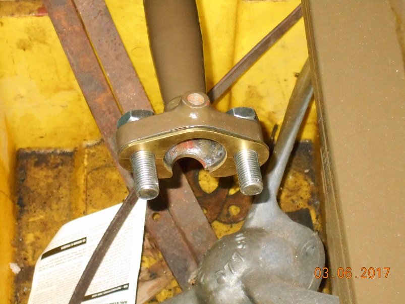
At the other end, the ball cups and compression springs were inserted and the end cover screwed on to tighten them against the ball at the bottom of the steering arm.
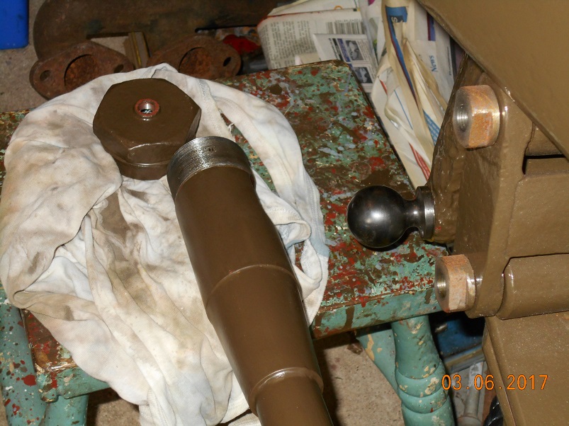


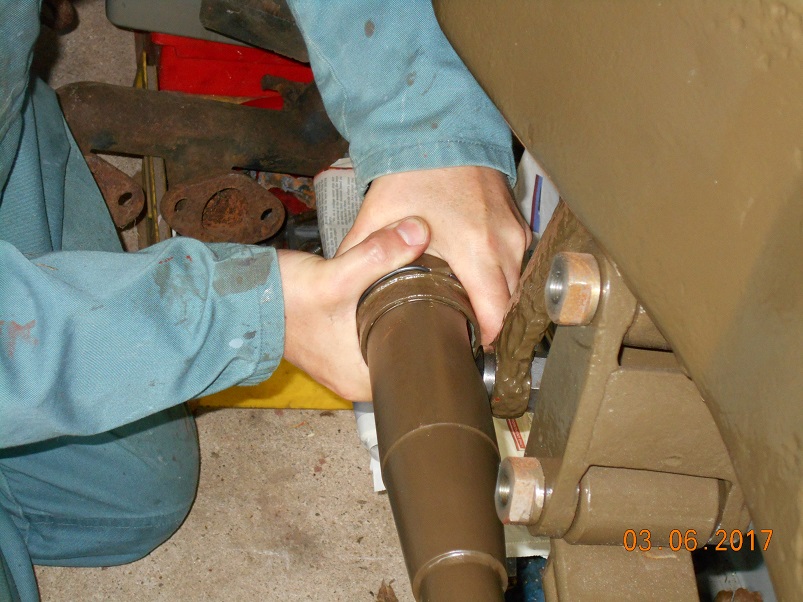

The end cap was tightened until the spring clip popped into the cross hole preventing it from unscrewing.

-
We are still doing things although never as quickly as we would like. Thoughts have turned to the floor and, although most is timber, there is a steel strip just under the fuel tank.

We took the opportunity to have a piece laser cut at the same time as the fuel tank components but without the slot for the steering column as I wanted to measure it on the job.

This was marked out and then cut.


As you can see, the slot is most of the way across the plate and this did cause me some concern as to its strength. If I had been designing it, I would have folded the front edge down but the original did not have this feature.

The plate sits on ledges at either end and is bolted through.


It was firmer than expected but, as you can see, it sagged in the middle.

For some reason, I had not properly investigated this feature on the vehicles I have studied but I got the photos out and had another look. This one turned up which is of the tipper lorry sold at the Tucker sale in the 1980's.

If you look closely, just to the right of the fuel filter there is something there. I think it is a piece of bent plate with a bolt through the dash and one through the floor.

Looking in the parts book, there are two likely holes so I have bent up a pair of plates, drilled them and they are now in the paint shop.


Looking more closely at the parts book illustration, there is a single hole to the left of the steering column. I believe this to be the anchorage point for the clutch pedal anti-rattle spring. I mentioned this to Father and he produced the spare one he had made when he made the brake shoe return spring anchors, all painted and ready to fit!

The other two holes are for the throttle pedal pivot and, as I had previously detailed that, I made it up.


Another Gosling silver-soldered fabrication!

All of these parts are now in the paint shop awaiting the next assembly session. In the mean time, it is back to pattern making. Only thirteen to go!
Steve

-
We also gave the pedals a trial fit. They look promising so they are now in the paint shop.

Finally, I tried to install Mark's most wonderful leather coupling between the gearbox and clutch.

The thickness was absolutely perfect and the bolts even went through every hole (the bit I did!). Dad had a rummage and came up with 19 off 5/8" Whit bolts, 3 1/2" long. We cut them down and drilled split pin holes and they look splendid. When he went looking for bolts, I was sure that he would find 17 (we need 18) so the Gods are smiling on us!

Fully installed, with the clutch-brake, but with the nuts un-pinned as I want to see if the leather settles and I can do them up a bit more.

We are very pleased indeed with this. Thanks Mark!
Steve
-
Thanks!
The gear lever is well clear of the pedals so there is no problem there. The hard bit is remembering that the handbrake is a pull-on type, not push-on!

Steve
-
We spent Sunday on Brighton sea front watching the commercial vehicles come in. We had a super day but it means that our deadline is now less than one year away!
Dad picked up the steering wheel this week after it had been powder coated. It is fine but not really quite as good as the Dennis. Never mind.


A trial fit to find the safest place to keep it!

Now that the drag link is finished, I could fit the last of my ball joints to the drop arm using a slot nut and split pin. No chance of losing it now!

Then it was on to the final fitting of the steering column. Father has machined the column stay so I just had to align it. This was easier said than done as the scuttle had never been on this chassis before and the steering worm is very slightly bent! To get over that, I messed around with shims and also slotted the holes very slightly.

This worked OK and the casting was bolted up. The outer column was then trial fitted and the steering wheel added to the top.


Looking good!

Once the drag link is painted, this can be fitted and we will have steering at last. Now we must make up the throttle quadrant and the hand levers for the throttle and advance.
Steve
-
Now, the pedal face. My pal, Adrian, very kindly machined the face and the letter 'C' on his CNC mill and it looked super.

I squared up the ends of the letter using a dental burr in my Dremel grinder. I couldn't help but imagine the cutter in my teeth. Ugh!

To fit, it needed to be curved so I needed to make up a jig. A rummage in the odds box turned this up which, I am reliably informed, is an 'executive toy'. You can unscrew the cap screws and screw them into different holes. Perhaps I just have a short attention span but I didn't find it very exciting so I decided to turn the block into my jig.

All a bit laborious as I could only use a single point tool. It worked though.

And then I did the job, in about thirty seconds! Never mind the job went so well because I had the right tool.


Another trial fit. As you can see, the pedal looks a bit long so I took a bit more off the end.

With the thought that the pedal was amazingly hard, I softened it back before taking it to see Barry for welding. As you know, my welding is terrible and I want some reliability in this one!


Barry did the job but he said the material was awful and the job did not come out very neatly. In fact, he had to get it pretty hot to be able to weld it at all. I wonder whether that is the cause of the original failure?


I noticed yesterday that there is a small eye on the back of the pedal for an anti-rattle spring. This I made up by cutting a piece of steel and then using my favourite silver solder to attach it.


The pedal shaft will now be sand blasted, filled and painted and that will be another one down. In the mean time, it is back to pattern making!
Steve

-
Something else which has been simmering for a while in this part of the lorry are the foot pedals. Long ago, I was given some very poorly pedals but from whence they came I know not. The clutch pedal had been snapped off and a replacement had been fabricated and welded on.

As you can see, the shaft has a distinct curve in it.

First job, therefore, was to straighten it, a simple exercise now that I have a press. What a wonderful tool!

The clutch pedal would have functioned but I felt that we could do better. The pedals were originally steel castings but I thought that a fabrication would be the solution. Fortunately, the brake pedal was sound, if heavily worn so I had a good look at it and drew it up on the board.


A pal very kindly prepared the files and ordered some laser profiles which duly arrived. Notice the slots and tags to assist with jigging for welding.


One piece was bent, another simple task for my home-made press brake in the press.


Next task was to remove the previous repair. I used a thin cutting disc in the angle grinder but it hardly touched it so hard was it! It took ages and I got it very hot indeed.


The I prepared the end for welding. I didn't want a plain butt joint as I was pretty dubious about the quality of weld we could achieve as there is obviously a lot of carbon in it. I therefore stepped it to increase the length of the weld.


-
Yes, Andy, I did puzzle over what to use. However, I had been given a bundle of small diameter silver steel rods and, as they were in stock and just the right length, I used one of them. It seems to be OK.
Steve :-)
-
After giving Father some grief about finding the ball sockets and springs, they eventually turned up on my bench! First job was to dress the locating peg in the ball cup back to 1/4" wide from the original 5/16" dia. in order to fit the slot. 1/4" is as wide as I can cut unfortunately but I don't think there will be any harm done. If anything, it will be an improvement as the contact area is significantly increased.

There are two cups bedded onto some very stiff springs. They are squeezed up by the end cap which is screwed down to secure them. However, the end cap could unscrew detaching the steering from the wheel to the great inconvenience of the driver so it is secured with a spring clip. This takes the form of a ring of spring steel with the end bent over and inserted through the cap into the drag link end to lock it. As you can see, our original has seen better days although there is enough of it there to copy. I used a piece of 1/8" silver steel which I curved in my bending rolls and then bent the end over in the vice. Finally, I heat treated it with the blowlamp on a fire brick, firstly to bright red before water quenching and then tempering to blue before quenching again. Despite the rather hit-and-miss approach it all went very well with a nice springy clip and none snapped off!


Now it is ready for the paint shop!
Steve
-
It is amazing what you can do with a few consecutive days of effort! Mind you, these have all been simmering for a while. Anyway, I have been finishing off the drag link.
As you can see, our original drag link was corroded beyond repair. In some areas, only the brazing material remained such was the depth of corrosion.


Some considerable time ago, Father made up a new set of parts including the ends for a new link.


As they were originally brazed, I have been sitting on them pondering on how to put them together. I have great confidence in the reliability of the silver soldering process so I decided that that would be the way to go. The strength would be there and I have the equipment and experience to do it. The only down side is the cost but for one-off, that is not an issue. The first challenge was how to get the solder into the joint. I could have put some down the hole and heated it until it ran out but that came with the danger that the steam produced whilst the flux was drying out would blow the joint apart. I therefore decided to drill a 1/4" hole at the end of the joint and feed the solder that way until it ran out of the other end.


This all went well and the solder ran through beautifully.


Then I had to do the other end. Much head scratching as to how to prop it up in the appropriate position but all went well and this one ran satisfactorily too.


It was at this point that I remembered that I had to cut a keyway on the inside before brazing! The plan had been to do it before it was too long for the lathe so I engaged in a certain amount of head scratching. In the end, I reversed my keyway cutting attachment so that it faced the tailstock. Then I made up a clamp to hold the link in a vee-block at the end of the lathe bed. The outer end of the link was propped up on a bit of wood and, fortunately, it proved secure enough to plane the slot. It is only an anti-rotation slot for the ball cup inside the casing. The cup needs to be free to move as the ball joint is trapped between two springs.


Another piece ready for painting and fitting. Hopefully, Father can find the tin with the springs and ball sockets in it. It hasn't been seen for a couple of years!
Steve
-
More work today prompted by the clutch installation. As you can see, there is a gap between the clutch flange and the gearbox input flange. This is filled with a flexible disc coupling of which the original was made of leather.

We are fortunate in that we have the remains of one to copy. Mind you, how they were made is outside of our knowledge. Fortunately another of our dear friends, Mark, a retired submariner, knows all about this sort of thing and very kindly offered to make it up for us. In fact, he made three as the main propshaft flexible joints operate on the same principle.


These are amazing pieces of work and must have taken him ages as well as the severe wear and tear on hands. Thank you Mark. The next challenge though was to put the holes in them in the right place. Now, how to you put a 5/8" hole in 1" of leather? An ordinary twist drill was suggested so I had a laser cut blank made to position the holes with extra screw-down holes in the edge to enable the leather to be trapped against a board.

Then another woodworking pal suggested using a 'Forstner bit' which is something I hadn't come across. It has the advantage of a sharp edge all round to neatly cut the hole without tearing it. I did a test piece and was pleased with the result.

Then I went for it!


The leather is sandwiched between two plates which spread the load from the bolts. These had also been laser cut some time ago. I cut and filed them for the Autocar couplings but I am certainly glad that technology has moved on and I didn't have to do that again!

These have a single securing rivet to each pair so I drilled through the leather, with a twist drill this time, and made up some rivets by softening some ordinary wire nails.


These went quite well.

Job done!

Now we need a clutch pedal and linkage but that will be a story for another day.
Steve

-
Do you think this might have anything to do with soldering pipework to carry portable water..?...:banghead:
Yes I am sure it does. They are removing lead from everything now but the replacements are never so good functionally although not killing you is a plus point......
Steve :-D
-
Hi Mike.
I can't quite picture what you are describing? 'A slice in the end of an old punch'? I'm afraid I just hit them!
The first ones I tackled were the baffle plates. They are easy as they don't have any corners.


I just clamped them between the flanging blocks and knocked them over with a planishing hammer using lots of small hits.


They were quite easy and came out well. I even remembered to make one of each hand!

Then came the end plates which were trickier because of the corners. One corner is 3" rad, two are 2 1/2" rad and the last is 1 1/2".

I started by working the straight edges over, either side of one of the larger radii.


I then moved to the corners, again using lots of small hits and working along and around, back and forth.

One of the tricks I have found is that you must not let the curved face kink. If it begins to go, I hold a dolly up behind the kink and knock the high spot back down.


Then it is a case of just keeping at it until it gets there. Lots of small hits.

On the tightest radius, I did put the propane torch on it to help things along. I couldn't quite get it red hot but it certainly softened and helped it go down.

Job done!

On the end of the fuel tank is the driver's instruction plate. I had one of these made in vitreous enamel many years ago and it has been hanging on my bedroom wall for all of that time! Anyway, I felt that the time has come to fit it. As it is screwed to the outer skin of the tank, I thought it a good idea to drill and tap the holes before soldering the skin onto the end thus removing the chance of puncturing the fuel space.

I laid it out on the plate and spotted through the holes.

Then they were simply drilled and tapped. The plate is a bit thin for tapping really but there are plenty of screws and the instruction plate is not very heavy so I think it will survive.

Time to start thinking about the wrapper. That is going to be a real pain to bend and is going to need some tooling. I also need to get the steel cut as a nibbler and file will be too much like hard work. The whole thing is assembled with rivets and soft solder so there are still a good few hours work in the thing!
Steve
-
The cap was a nice turning job in the Colchester.


A bit of porosity but nothing to worry about.

The internal thread was screw-cut at 6tpi. This is the coarsest we have ever done and setting up the machine caused us some head scratching. All went well in the end.


The cap is ready for knurling around the rim. That one might be a bit of fun as I have always found the process a bit hit-and-miss. We shall see.


Now, the top and bottom of the tank are done so time to think about the ends. The end plates are rivetes in with the flanges facing out and then have filler plates sweated on top. I can't see why as it is only a cosmetic thing and seems a bit of a waste in war time. There are also two baffles in the middle. I drew them out and another pal put them onto CAD and ordered the blanks up from a laser cutter. In the back left of the photo, you can also see some pieces of 12mm plate that we had cut out for use as flanging blocks.

First job was to prepare the flanging blocks by breaking the corners of the block to be used on the inside. This allows a much better bend of the end plate and removes a stress concentrator. This was done by the use of a flap wheel in the angle grinder and took very little time.


-
Yes Andy. I would definitely consider that Dennis vehicles are more refined than Thornycroft which are in the more 'agricultural' league. They still seemed to work though. I hope ours does!
On that front, we are still doing things but, in our usual manner, several things at once. The current major items are the steering column and linkage, the clutch installation and the fuel tank. I try to make a post when there is something to see but sometimes, they seem very far apart. I just can't keep up with dynamo Hawkins! Never mind. Here is another installment.
We are fortunate to have the remains of an original fuel tank. Unfortunately, we have deemed it beyond repair so we are making up a replacement.


A while back, I reported the manufacture of the new sump and clean up of a fuel tap found at Beaulieu Autojumble so these were the first two components.

Many years ago, I made up a pattern for the fuel filler cap. This was only my second pattern and I was not very generous with the outside diameter.


Dad inspected the castings and reckoned that he could use them.


Before he started to machine them, we decided to salvage the filler neck from the old tank so that he could try it it in the new thread as he went.


I cut it out with the disc cutter and Father cleaned it up before dismantling it.

He took the rivet heads off the back and then punched them out whilst the solder was warm.


A good wire brushing left us with a sound filler neck and also a doubler plate for inside the tank that we can re-use.


-
Spectacular pieces of spinning. One needs to have some confidence to stand so close to a disc going that fast!
I have just been looking back through the postings and have realised that I have already posted about the steering wheel last December. Sorry about that. That is what happens when so many things are going on concurrently! Anyway, Dad has taken it for powder coating today.
In the meantime, we have been looking at the clutch brake assembly. This is a leather faced frame which contacts the back of the clutch when the pedal is fully depressed to slow the clutch and allow faster upward gear changes. First job was to find a piece of leather. This came, courtesy of Ebay, from Sri Lanka and is claimed to be 'Buffalo Hide'.


I cut a ring out of it using scissors and a Stanley knife.

Then I had to make some shallow countersunk rivets as we didn't have any. I simply drilled a piece of steel and then lightly countersunk it with a large drill.

Place the rivet in the hole.

Thump it home with the hammer.

and face off the head to suit.

Rivets secured in the normal way.


And the brake frame was temporarily fitted. It will need setting up once the coupling and clutch is completed but for the time being, that is another job done.


Father has picked up the steering column support bracket from the foundry this week.
[ATTACH=CONFIG]124732[/ATTACH]


Once he has finished the fuel filler cap, that will be the next project.
Steve
-
Readers may remember, from post 1470, that we made up a pattern for the steering wheel muchearlier that we needed it so thatwe could get three castings made, one for Dan's Halley, one for the Coventry Maudslay and one for ourselves. I machined the bores early on by bolting the wheels to the faceplate of the Colchester.

Unusually, I didn't take any pictures of that process. However, all went well except that the gap bed on the lathe was not big enough to take the wheel when reversed so we had to face the other sides in the mill. Unfortunately, even then, as you can see, my mill wasn't big enough and it was done in yet another friend's machine. Where would we be without our friends?


Since then, the wheel has been sitting on my bookcase but the time has come to get on with finishing it off. First job was to run the ends of the spokes into the hub. This was done with the aid of the trusty Dremel pencil grinder and files and emery.


Then Dad took on the thankless task of working the whole casting to a good finish. This was very long winded and tedious but Dad removed the bulk of it. with a power file and emery.


I then took the thing in hand and went over the whole surface again with finer emery and needle files to pick up any oddments that had been missed, another 20 hours of work. Finally, it is ready for the powder coater's.

Originally, it would have been coated in a layer of celluloid all over but we found on the Dennis that a thick glossy powder coat produces a quite acceptable effect at a tenth of the cost. Dad will get that in hand this week while we press on with the rest of the steering column.
Steve
-
A little while back, Dad picked up the fuel tank sump casting and also the magneto advance control rod support casting. The foundry were not having one of their best days but Father has cleaned it up and then machined the hole through the middle.


Two bolt holes and that this another piece ticked off.


Once the steering column is complete, we can start making the linkage to connect them all together.
Steve.
-
Thanks for the guidance with modern fluxes, John. I have not yet had any success with the stuff but now that I have a £10- tub of the stuff, I will keep trying!
I will have to solder up the fuel tank in due course and I think I will stick to solder paint and Baker's fluid as per the Dennis tank. I know how to make that work!
Steve.
-
Another part of the column is the cast brace which supports the bottom end. This is the one on the Carlton Colville lorry.

Another pattern making job which I started by turning the boss for the end.

Then came the top. It has curved sides which I puzzled over for a while until I spotted some concave moulding which I glued along the edges of some MDF.

Whilst the glue was going off, I cut the boss in half and filled the gap with a piece of plywood. The purpose of the boss is to provide both halves of the clamp in one piece. The plywood made it oval so that when cut in half, there is a machining allowance left.

In the meantime, the edges were extended downwards with further strips of MDF.

The kit of parts is growing.

The 'ears' on the boss were built up on both sides and the exterior of the moulding was planed to a curve to match the interior. Then the flange was attached to the end.


The flange was cut out and the corners dressed to match the interior curves. Some filler was added as well to allow the pattern to be drawn.


The usual two coats of Bondaprime and Father has another one to take to the foundry.


There is still a way to go but we are coming on. Steering wheel finishing, throttle quadrant and throttle levers remain.
Steve
-
Thanks Andy. I try to avoid the plumbing!
Steve
-
Messy but satisfactory.


A coat of primer to keep the rust off and now that is ready to fit as well. It just needs the clamp to support it but that is a story for another day.

Steve
-
As we mentioned before, Father has picked up the throttle control support castings from the foundry.

This week, he has machined them on the Colchester lathe.


Quite straightforward really although this one was a bit trickier to hold.


He had cut off a length of column tube to try in the hole to get the fit right.


The spindle holes were then drilled.

Followed by a good clean up.


The castings are secured to the tube using soft solder. Unfortunately for me, Father's tin of Baker's Fluid had corroded through and been disposed of. I therefore went to the local builders merchants and bought some 'soldering paste'. This looked rather like vaseline and, to be honest, I didn't have much confidence in the stuff


I had a go but could not get the solder to run. This could have been the solder which, I believe, was of the lead-free persuasion. I don't have much confidence in that either. Can anyone offer any suggestions on using this combination?
Anyway, I cleaned it all up and used good old leaded solder paint to tin the joint and then fed in some electrician's solder which I knew was the proper stuff.


This worked well so I used a rod to align the two castings and soldered the second.

-
We have made some good progress this week. Dad has been steadily completing the finishing of the paintwork on the hood frames and what an awkward job it has proven to be. They are not heavy but really cumbersome and we just don't have the space. Anyway, in spite of that, all are now complete so I spent yesterday making up a simple jig to hold them in the correct relative positions ready for the canvas to be made.


Father and I took the lot up to Jim Clark at 'Allied Forces' for him to have a look and, hopefully, agree to make up the hood for us. This, he is going to do along with the main tilt to go over the back, the seat cushions, and the cab doors. We left some photos for him to mull over.

"What have I taken on here?"

That is one job off my critical path and it is back to the steering column for a while.
Good luck Jim! (And thanks!)
Steve


WW1 Thornycroft restoration
in Pre WW2 vehicles
Posted
Next came the pedal shaft.
This was quite straightforward although the pedals don't align in their normal positions. Something to be looked at when they are set up. The brake pedal is retained by a steel collar which was missing so I turned on up and it was soon fitted and pinned.
Finally, the steering wheel was fitted using the nut which Father had just painted black to match the wheel.
Now we not only have a hand brake but we have functional steering as well!
A most satisfying day.
Steve