


Old Bill
-
Posts
1,669 -
Joined
-
Last visited
-
Days Won
33
Content Type
Profiles
Forums
Gallery
Blogs
Events
Articles
Store
Downloads
Posts posted by Old Bill
-
-
Father has been busy and I forgot to mention it! The front cover from the differential housing was missing so I made up a pattern and Dad had it cast.


He has now machined it up including a felt seal groove and it is ready for the paint shop and fitting.


One more down!
Steve

-
In regards to your core boxes.... been there done that!
I found the simplest way was to make male masters than use those to cast the actual core box in plaster-of-paris.
Thanks Terry. I knew I should have asked you first! I am well on the way carving them out at the moment but should I give up in disgust, I will try this method.
Thanks for reminding me!
Steve
PS. Looking forward to hearing your engine too!
-
Is there any chance of using ADI? (Austempered Ductile Iron). That's basically cast-iron with a post-casting heat-treatment.
Thanks Andy. Yes, I did think about it but as I will be brazing the ends on, I think it likely that I will mess up the heat treatment. I'm sure that SG will be fine.
At the end of my last post, we were fixing the seat down. At the front are two coach bolts but the rear is secured with two straps so I have made these up. Starting off with two flat strips with holes.


Then a slot and two studs.

These were welded by our senior welder at work. I don't want to risk them failing whilst I am sitting on it!

Finally, a couple of hours with a file finished them off. They are now in the paint shop.

I have been doing all those boring things like fixing leaks in the attic and broken horseless carriages which just have to be done no matter how little one wants to. I have, however, found some time to make up the silencer baffles. I cut them out with a nibbler which is a wonderful if very frustrating tool to use. It can get anywhere but maintaining a straight line or constant curve eludes me.


I don't have any to copy but there is a small picture in the parts book. Unfortunately, the book doesn't give quantities of parts but I have guessed four and spent a long time counting holes to get the right number in the plates. I think there are 117 altogether with three larger ones for the spacing bars.

I used a hand vice to hold the stack of discs and drilled them through (with one out of position. Very irksome!)

I screwed the stack to a board which I held in the four-jaw and turned the periphery.

Something else in the box ready for use.

I was fortunate to be able to attend Duncombe Park Rally near Thirsk on Sunday last where I met John Marshall and saw his J type. I had a ride and he has very kindly loaned me his spare high-level water branch from the top of the engine. Unfortunately for me, he wants it back but it will make an excellent pattern to make a copy. I just need to make up a core box.


Core box is the next task, once I have worked out how to do it. Lots of MDF in this one! Will keep you posted.
Steve
-
Thanks for posting Robin, but I can't find the film when I am on your page. Facebook is not my regular domain and if it doesn't have a starting handle, I am flummoxed!
Steve
-
How did you cut the keyway, Ben?
Steve
-
I read it as 20 nuts for £3 which is £0.15 per nut. Am I being dim?
Thanks for the link though. The next lorry is a Peerless with wooden wheels and a wheelwright is a good contact to have!
Steve
-
Thanks, both of you. Well worth keeping in mind for next time.
Steve :-)
-
I have not yet decided what I might do, as restoration is probably out of the question. Initially, I would like to set the M4 engine up as a running display, to compliment my Gardner 6LX and Foden FD6 engines that I take to shows.
Hi Ian.
Glad that you found us! Restoration is never out of the question. You have far more than we did when we started! If there is anything we can do to help, just let us know.
Welcome in!
Steve
-
We seem to be reaching a concensus in that they were cast but probably in steel. As I am after more toughness than grey iron but we are only driving a leather coupling, I shall have a go and get them cast in SG iron. That will be the most straightforward solution I think. Thank you for all of your thoughts.
I went down to Devon at the weekend, mainly to confirm that my bonnet drawing was correct. I had originally decided on the front and rear profiles and made some plywood patterns.

Unfortunately, when held up they were not quite right.

I made some more which I brought down to check and these proved acceptable so the drawing has been signed off and sent to another pal to make us a bonnet.
In the mean time, the timber for the floor has arrived from Mark the chippy.


These are a super job and went in beautifully. However, we now needed the bolts to secure them. As we have mentioned before, old coach bolts have square nuts and these are proving surprisingly difficult to get in this country. Fortunately for us, the UNC bolts made in the USA still have square nuts so every time Time visits his in-laws, he comes back with boxes of bolts in his luggage. Goodness knows what 'Homeland Security' make of him! A quick dip in the supply found the perfect bolts so that was that problem sorted.

The right hand side has a slot for the gear shift so that was cut and the second piece fitted.

We couldn't resist pushing the seat forward to its correct position.

A couple of rebates to clear the bolt heads and we had a floor!


Dad had previously prepared the steel angles to hold the seat down so now that it was correctly positioned, we drilled the last four holes and fitted them underneath.

The front is held down by coach bolts through a rail glued to the front panel. The rear has a pair of steel brackets which are currently in manufacture. The seat can be finally secured next time.

Interestingly, it appears that the pedal slot will go through the full width of the front plank. I think we will leave cutting that until the pedals are finally set up. I am hoping that it will become clearer then!

Steve
-
If only!
Steve

-
Nice to see it running!
Steve :drive:
-
Steve,
One question - all these bits that you have made new by casting, were they originally casted? Not drop forged?
I am not an expert, but sometimes I find it difficult to see if an old rusty part is forged or casted.
From what I learned during my time studying to engineer, drop forged is a lot stronger than casted, but it is also a matter of alloy being used.
It would be of interest to know your opinion on this and what you have found out during the restoration.
As the director of the Swedish Tank museum I sometimes have to wear a tie, but most of the time I have dirt under my fingernails due to tank and vehicle restorations in my spare time.
Now we have recieved the new track pins for our WW I LK II project so now we can continue with the tracks.
Hi Stefan.
Pleased to hear that you find it useful!
The castings we are making are are direct replacements for castings we don't have. A lot of them could be fabricated but whilst I can make patterns, I can't weld so casting is my preferred method. Of course, we try very hard to produce bits in the same way as they did 100 years ago and castings were much more common then anyway. When we find forgings, we usually replicate them by fabrication or carving out of the solid but we have been generally fortunate with the Thornycroft in that there aren't many and the critical ones we have. The only place where I think we have used a casting instead of a forging is the drag link ball end. This is a critical component. However, when the lorry was built, only grey iron would have been available but we have been able to use SG malleable iron which is very much tougher. There have been one or two raised eyebrows but I am sure we will be fine. No doubt time will tell!
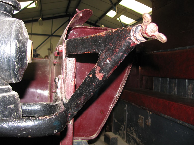
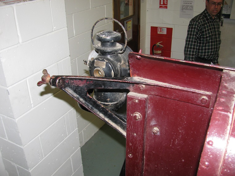
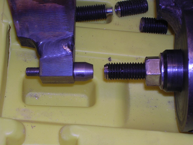
One item I am pondering over at the moment is the propshaft end. This is the one at Carlton Colville:

It is brazed to the drive tube but is it a forging or a casting? If it is a casting, is it iron or steel? We don't have one so we are going to have to make a replacement. My guess is that it is a steel casting but they are difficult to get so I am wondering whether we can get away with an SG iron casting. Please may I have some views? SG iron is easy to get so I would really prefer to go that way if we can!
I am enjoying your tank project. Do keep us posted with progress!
Steve
-
It is amazing what turns up. One of my pals has just sent me this:

I hadn't realised that Dennis had bought their radiators out although it is not surprising really. They are a very tool specific item to produce. Another little gem!
Steve
-
Steve,
A very nice pattern ( .....for a dinosaur )! Equally impressive though was the superb thin wall casting. Bridport really do seem to do a lovely job on little one off's where there cannot be too much money to be made.
Yes, it is nice to have a sympathetic foundry so close to home.
The printed pattern has produced a super result and we are very pleased. It is a very good way to go. However, I will continue with wood patterns because I can do them myself without imposing on anyone. The 3d printer is a specialist bit of kit which I shan't invest in for ourselves and I certainly don't want to get into the situation where whenever I contact someone, the first thought is. 'Oh no, what does he want this time?' Mind you, the prop shaft spiders might suit this process very well!

Steve
-
Those brackets illustrate perfectly your incredible attention to detail: making patterns and having castings made to perfectly replicate the original, where lesser men (myself included) would have just cobbled together something that looks something like it out of some steel angle and bits from the scrap bin. Nice work.
Thanks!
-
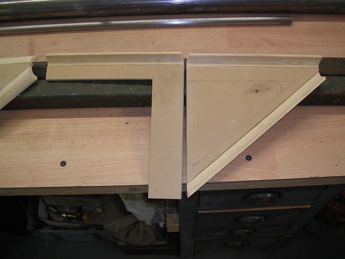
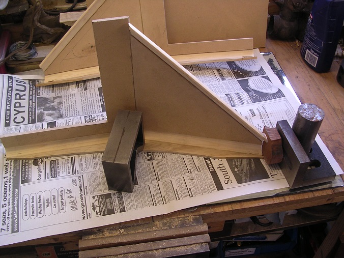
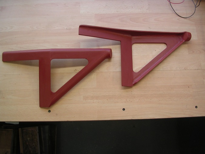
More pattern making going on. On the scuttle, on each side there are the supports for the cab hood frame. These are cussing awkward castings! They are thin, radiused and are set back as well!
After some head scratching I thought that I could assemble them from some sheet MDF and strip mouldings to get the internal radii. I had drawn them up long ago so at least I knew what I wanted to achieve.


The outside radius was relatively straightforward and achieved by gentle use of the plane on the outside of the moulding.

Then I had to set the angle. I sanded it to the right angle best I could and then cut some ash strips to brace up behind.

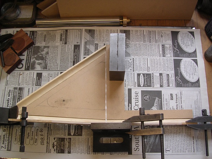
Blocks on the end, made from recycled mahogany, were glued to the ends.
These were then shaped using the Dremel and the ribs were cut back using Grandfather's spoke shave. He was a shipwright by training and I would like to think that he enjoys seeing his tools loved and used.
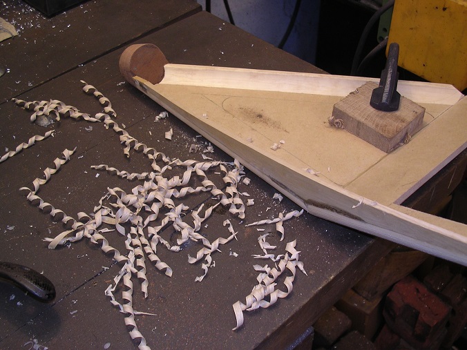

Time to cut the aperture. These were drilled at the corners and then profiled with a coping saw before finishing with glass paper.

A bit of filler.

Ready for paint.
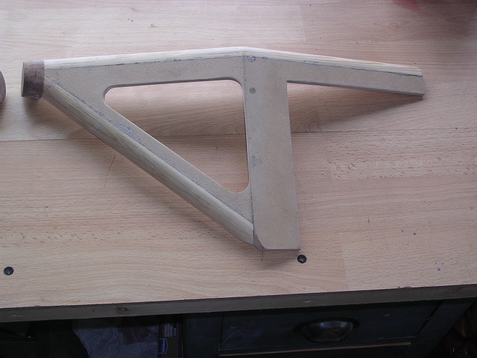
The usual two coats of Bondaprime with a polish with steel wool.
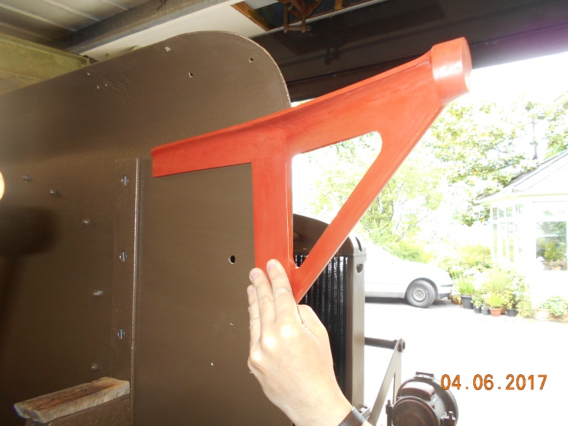
A trial fit.

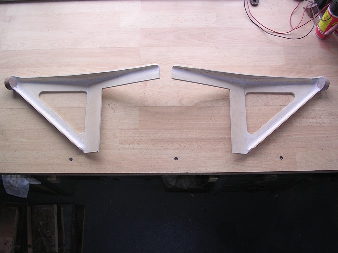
New castings, picked up yesterday!
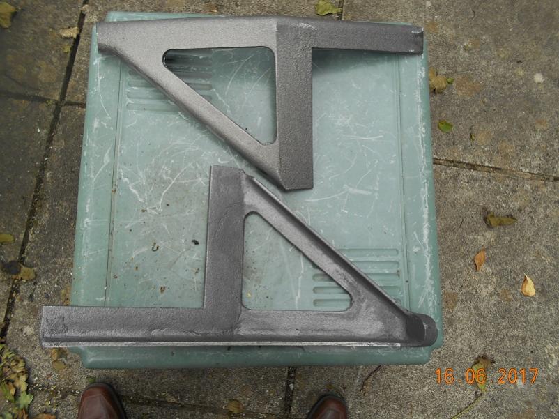
Only ten more patterns to do!
Steve :-)
-
We can only do it with help from our friends!
Steve :-D
-
Look what we've got! Father has been to the foundry today and picked the quadrant casting. It has come out really well so it only remains to give it a bit of a clean up and drill two holes. One more down!


The foundrymen were very impressed with the pattern. Thanks for that Will, Adrian and Barry for the team effort!
Steve :-)
-
Nice job. Do you have your own foundry facility as well? I have never been quite that adventurous!
Steve
-
What a nice lorry! I am looking forward to this story!
Nice piece of turning too. Did you do that by manual methods or CNC?
Steve :-)
-
We have been thinking about how we are going to put the fuel tank together as it is of riveted and soldered construction, the same as that for the Dennis. I managed to make up a rivet squeezer for the Dennis by making some adaptors for the jaws which worked quite well. However, quite out of the blue, Andy very kindly offered me the use of his squeezer which offer, I have gratefully accepted. This one started life as a basic hydraulic cable crimper.

However, Andy has converted it by making and arm and adaptor to carry rivet snaps.

It has proven successful but, unfortunately, the anvil, made from an M12 grub screw, broke out of the side and was repaired by welding. This had the effect of jamming the grub screw so, with Andy's permission, I cut the end off and had a block welded on by our senior welder at work.

This was done using the TIG process and came out well.

My next challenge was to drill a new hole for the anvil, in line with the centre of the thread. To centre it, I machined a close fitting boss which I bolted to the milling table. I then clocked it in line with the quill and locked the table. Then it was simply a case of dogging the arm down and drilling through.


I tried a different concept this time in that the hole is only 1/4" dia so the anvil bears against the face of the arm and is only located and secured by the centre stud giving a solid surface to push against.
All ready to go once the wrapper is bent up.

Bending the wrapper is a bit of a challenge. There is one 3" radius, two at 2 1/2" radius and one at 1" rad. The rollers at the railway are 4" diameter and long enough so we should be able to do three of the bends there. However, the 1" rad is a bit more challenging. I have determined to push it into a vee-block using a piece of tube. As the material is quite thin, I think a wooden block should suffice so I have made one up from timber lying around.


Tim then came up with a piece of scaffold tube 44" long. The tank is 40" so this is just right. It is also 1 15/16" diameter so it is perfect that way too! Here is the final assembly.
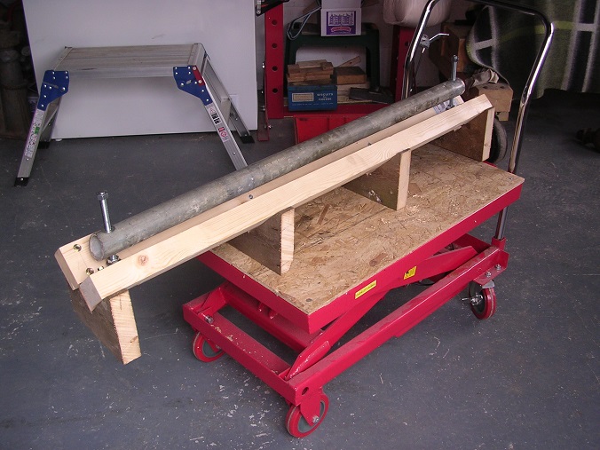
All ready for the next step!
Steve
-
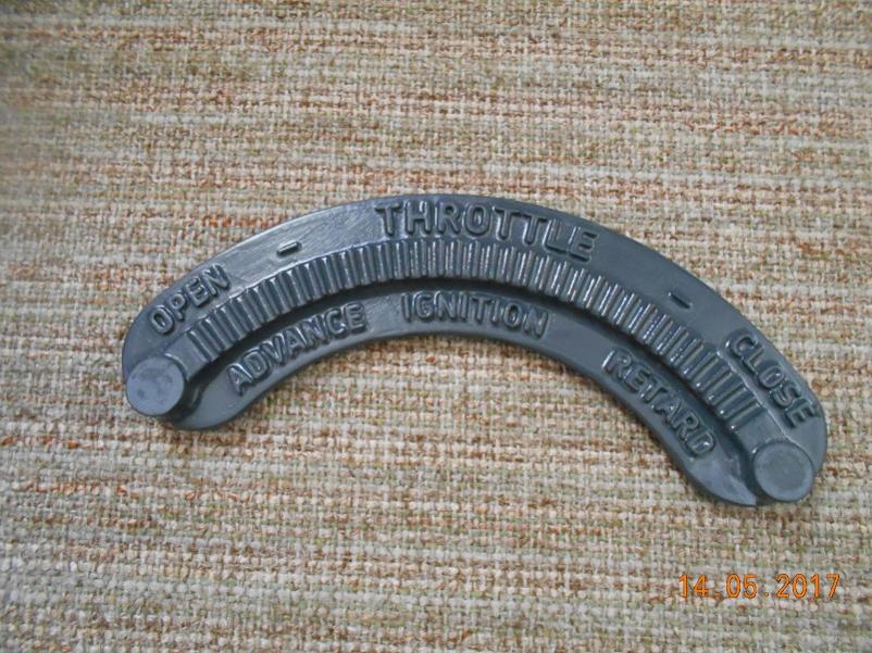
As I have said, we usually have several things on the go at once and one of them is the hand throttle quadrant to mount on the steering column. (The lad in the picture is the grandson of one of the Carlton Colville museum volunteers who kindly let us in.)
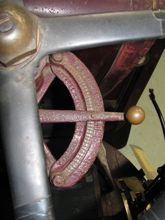

As you can see, this is a casting and patterned on both sides. I was puzzling over this one until young Will kindly offered to model it for me in 'Solidworks' CAD software so that it could be 3-d printed. He sent me this rendering of it and it was almost spot on.

His Dad had a final tweak of it before I emailed it to Barry who has a suitable printer (A Christmas present from his good lady I believe!) and he printed it.

Unfortunately, it is stepped underneath and the printer, which operates like a very fine glue gun, had nothing to lay the bead on. To get around that, he laid up a fine structure to start it on with the intention of breaking it off afterwards.
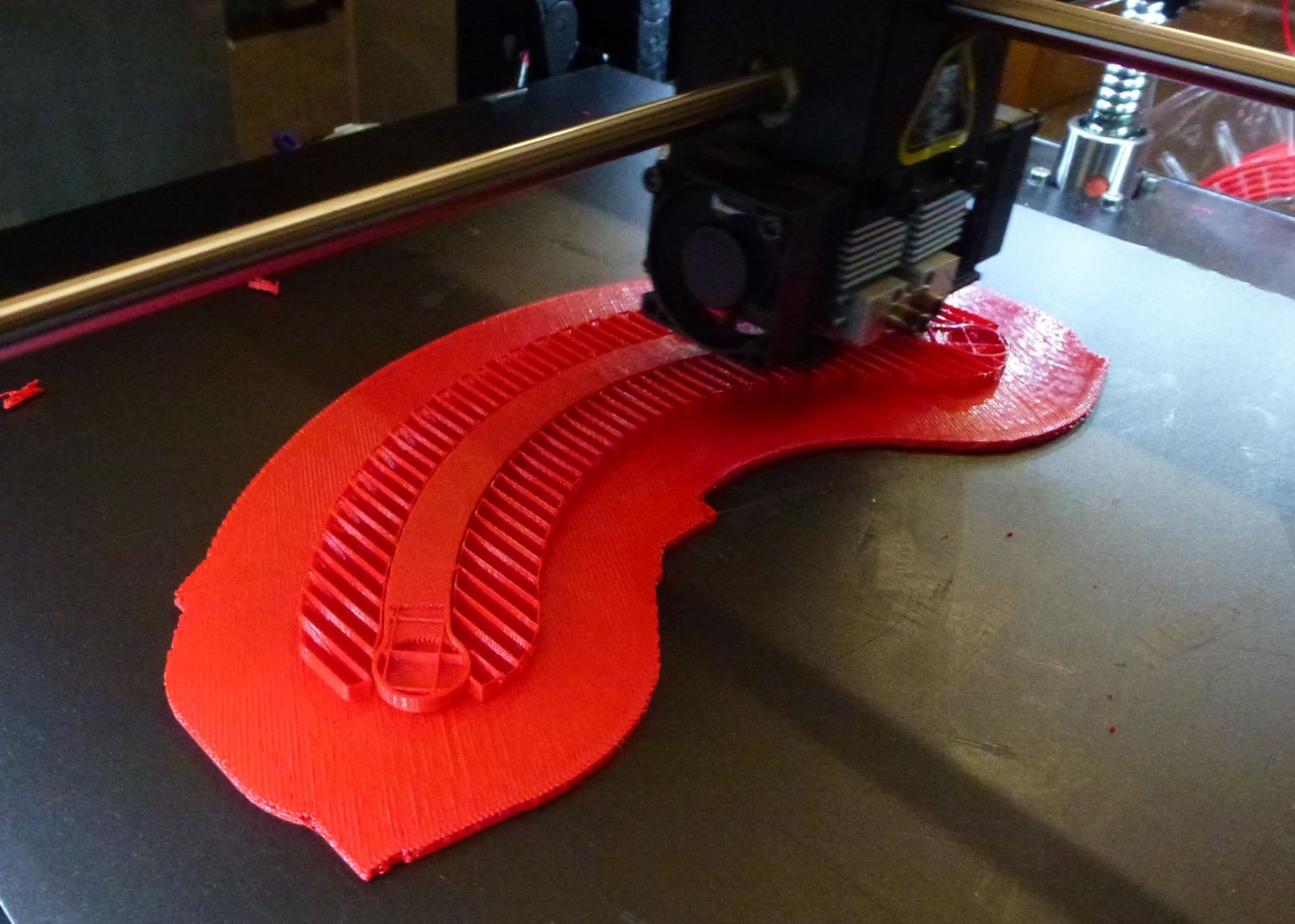
This worked up to a point but the surface it left behind was not really good enough.

He had another tweak of the model to make it in two pieces which could then be bonded together afterwards.


This was much more successful.

Two coats of 'pattern coat' and it was ready to go.

Father took it to the foundry yesterday so we will see what they make of it. That's one more down and twelve to go!
You can't do this hobby without your friends. Thanks Chaps!
Steve :-)
-
The two bolts holding the floor plate to the scuttle through the newly made bent sections, have round heads. I could not tell if they were rivets otherwise. That is looking over the one here.
One for the rivet counters!
Doug
Thanks Doug. Every little gem of information is valuable. I suspect that there are only really two rivet counters for J-types, you and me!
Steve :-)
-
A great step forward, Steve. Doesn't it give you a thrill when your restoration job starts to go back together and look like a truck once again.
Regards Rick.
1916 Albion A10 Chassis No. 361A
Hi Rick.
Yes, immensely satisfying! We spend ages pottering along with no visible progress and then there is a sudden step change!
We are, of course, doing lots of little bits all at the same time so we end up with gaps in the narrative. Sorry about that, I'll try to post some more shortly!
Steve :-)


WW1 Thornycroft restoration
in Pre WW2 vehicles
Posted
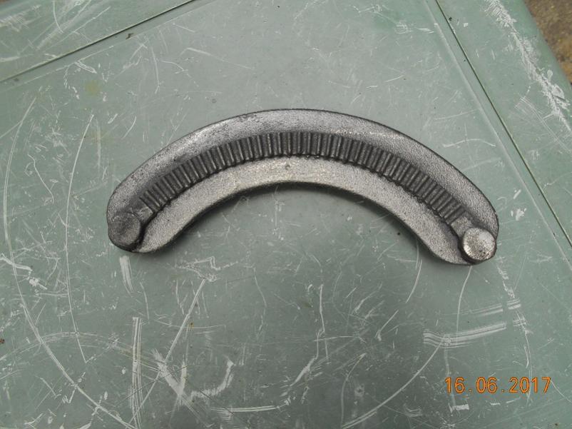
It is interesting that you should ask that one Andy, as Barry has just very kindly printed the patterns for the silencer ends for us. This is an original, photographed many years ago.
And these are the patterns and core boxes.
They are super objects and will do the job nicely. However, their surfaces have a definite texture to them which will allow the sand to get a 'key' and make them difficult to remove. Barry recommends 'Pattern Coat' ( http://www.easycomposites.co.uk/#!/patterns-moulds-and-tooling/pattern-making/composite-pattern-coat-primer.html ) which he applied to the throttle quadrant to such good effect. It builds well and with a rub down took out the printing lines nicely. Father has just bought some and I will have a go with it shortly.
Steve