


cosrec
-
Posts
1,234 -
Joined
-
Last visited
Content Type
Profiles
Forums
Gallery
Blogs
Events
Articles
Store
Downloads
Everything posted by cosrec
-
Had a real pain of a day. Covinced my self i could sort this solinod wiring thing out. tried every thing/combination i could think of with wires. Richard was correct about the little black things in plug they where diodes not resistors. So thankfully this reduced the total combinations i could try.At one piont i added a 2 homemade resistors made out an old element out of a hair dryer so i could put 6 and 18v voltages down the different wires. Remember all the time i had to have the engine running at 800rpm and i was in a shed the vibrations kept working lose jury rigged connections i had made. I got so i was about to lose it big style and total result nothing. Peed of i decided to give it a rest whilst having a cup of tea i started to think about it again maybe i am trying to make this too complicated. Back out again removed the plug of soliniod. this revelled four terminals only three of which have ever had connection to them. Started engine again put a +feed to the terminal that had never been used and -return to the terminal next to it Bingo satisfying whoosh lever moved and winch started going round. Moved -return to another terminal whoosh again winch moved opposite way. Sat there full twenty minutes moving wire from terminal to terminal could not belive it was that simple. Got to be a snag here some where i thought am overloading the solinoids with 24 volt so tried again put my home made resistors in to reduce voltage to 6v(nothing happened) 18V (lever moved but only slightly). Next put full 24v in once more and have left for an hour engine not running of course. On return felt soliniod maybe warmed up a little but barely detactable. started engine again still working. Result i am a happy chappie i know a bit of simple wire swapping in the plugs and throwing away diodes i have a dead simple to wire up system that will connect to my radio remote when it arrives. All being well should be able to get legs up and working from leg stations switches next time i get chance to work on it. Conclusions from all this i have no doubt that the soliniods have originally being wired to some sort of proportional control but how the hell this was i dont know and now i am not too bothered as the unused terminal has enabled me to achieve what i wanted to do. By the way thanks for the advise from NOS and Richard Farrent As a little aside to this i have up to now removed 6kg of wiring from original thats about £30 to by a pint to celebrate
-
The levers are manual directly on to the actual spools and all work great. Out of the back of the spool valve are the main pipe outlets which go of to the rams winches etc at the front of each spool are two smaller pipes that go to individual valve blocks all linked together with very complicated steel hydraulic piping under each individual block is another oblong sqaure block with a standard connector on it. I guess this is some sort of solinoid. When i say connecter i mean the sort with the screw in the middle and when pulled of it exposes three terminals on the block. As i said i would a have experimented today with eg your suggested wiring method or perhaps swapping polarity or feed in and swappin wires out but it put me of finding these little resistors in the back of each plug linking all three wires together. I have no worries at all about fitting the remote just how to wire to actvate the solinoids
-
Had a look at Foden again to day. Removed original joystick from leg station to day they are a simple bank of four on/off switches. Common feed 24v that gives out 24v down one of four wires dependinging which way the joystick is placed. The joystick switch is a XD2 PA24 and on the internet it is decribed as a four way on/off. This pionts to the solinoids that are controled by these switchs not being proportional. Athough i guess something could have happened to these signals on the way through that big circuit board. Next i stripped out all the wiring where it came to the main box from the 11 solinoids so i could identify wires to each individual solinoid. This done i have ended up with 11 sets of three wires going to each individual hydraluic spool soliniod. Plus two wires going to another solinoid i connected a live and return to this and found it worked via air the freewheel for rear winch. I then tested with a 24v test light individual wires coming from each set of three wires. I found no matter which way i put feed in both the other wires lit up test light. Confused i took of the plug to the solinoid and on striping the plug found the wires were joined together by what i presume are resistors. So if any body can help how should these be wired. The two taps metioned by richard are at the moment both in the flow through position
-
Many thanks again yes i noticed these its too dark to go look now but i climbed on a foden a week or so ago and noticed these little taps had locking wire on mine dont so another lead. Plenty more to go at now
-
many thanks for that will give it a try next time i have a look. I suppose i could check out by testing voltage out of side leg switches as these are the original 4 position switches that control two spools each. all spools on all hydraulic functions look identical
-
I think you may have something there as it will have been proportianal control originally. I dont seem to able to find any makers name on the spools. Vehicle is insulated return what i have done is find common wire connecting negative and then being putting current up one or other wire but nothing. Ithink the problem lies in the pilot side of hydraulics is not getting pressure possibly because the 2 wire soliniod is not activating internally. i guess a hydraulic circuit diagram+ wiring diagram might be the first place to look any body know where i would get one
-
No i have ripped out the whole of the circuit boards and i am going direct to solinoids
-
In need of a bit of knowledge/help here. Have done a bit of investigation on crane and all other hydraulic functions. in readiness for fitting radio remote. If am correct each individual spool is operated by double acting solinoids so have located three wires to each solinoid. But if i power these up nothing happens. Further investigation i found another solinoid near the wiring box i guess this is to activate the whole system the solinoid has two wires to it. It tests out as being good circuit wise but still nothing happens when power is applied. Any ideas it seems as though the system wont power up the all function work fine on manual levers am i missing something somewhere
-
Hi my idea was to work the under lift and both winches from hand held remote the side stabilizers from the switches that already fited and make up another switch board for the rear legs. Call me old fashioned but for the crane functions i dont think you can beat the hands on feel of levers. We have a hiab with remote control and i hate it as it has no levers as such and i dont take it on recoveries if there is another truck in the yard. I have by the way got the circuit board and it it looks ok having being examined and passed 2009 but i took it out as i like simplicity and the functions i want on remote arnt too sensitive. Thanks
-
Thanks for offer of help. If i dont reply its because i am away for a week on holiday Regards Steve
-
The wiring has actually got got numbers printed along its length on the insulation what it means or how it works as yet i dont know. But will get sorted Will measure boom length an put up guessing its around 18" longer than original plus has 52" hydraulic extension plus spec head will add a bit more length pick a coach up tell you later when i try it out the flex is the original that went over the front axle My thoughts on all milatry spec wiring or piping is why use 1 wire pipe when you can make 15 do the same job
-
"It is not enough that we do our best; sometimes we must do what is required." — Winston S. Churchill What i call having a go

-
had a cautious look in wrecker wiring box today Looked like an explosion in a spaghetti factory. Wiring not my strong piont so will have to swot up a bit to fit wireless remote

-
Actually further away than it looks on picture but point taken re air pipes
-
Got bottom boom powered up shows max extension should be a lot handier than original. Tee Head is fixed design with adjustable tool holders as per modern wreckers. So straight away big saving on weight and locker space dont have to carry about those three Tee Heads that come with standard EKA package


-
Exhaust remounted lot simpler stronger rig with not as many parts to rot go wrong just need a rain cap on it now


-
Thanks for offer of help with ispl but am ok up to now but things could change. I am however after info on what pressure the main relief valves should be set at on the crane valve block and the big bank of spool valves that control everything else if anyone knows Regards Steve
-
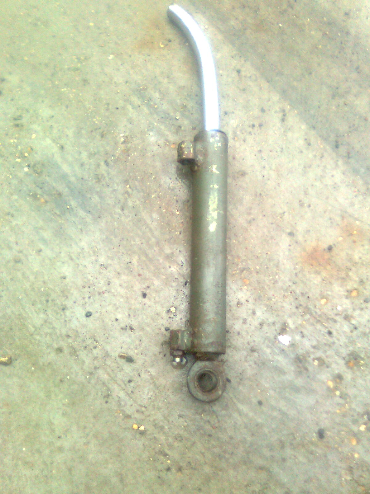
Thought I might get on well with Foden this weekend but not to be. First job Sat was to get longer bottom boom powered up and modify downward part of EKA boom to clear pipes not to be we had no ferrels to make up pipes. Bank holiday weekend meant that job was on hold. So underneath front end sort out sticking front brake shaft. Tried greasing no difference. Seem free enough when brake was applied but stuck on every time and had to have a clout with hammer to release it. Decided to wind of spring pot and take clevis out of slack adjuster and work with a piece of pipe on slack adjuster. Clevis would not move. Tried warming freeing oil no luck. Ended up burning yolk off. In the end found out this was the problem clevis had seized in both yolk and slack adjuster. New yolk and S/H adjuster good as new. While underneath noticed exhaust bracket was loose at O/S where it bolts onto engine mounting cross member. Simple tighten up bolt. No way tried every thing in the end had to drop exhuast of to get in then found bottom flange on engine cross member had cracked so in with grinder v it out weld that up. While moving closer to workshops to weld found out could not steer it steering was fighting back. So underneath to check noticed front diff lock engaged. (I haven’t got warning lights working yet). Checked lever control in cab OK take airline of activation pot OK get hammer to arm on axle solid. Turned out this was another seized yolk and pin. About 2 hrs to sort out. When done thought I would out of caution check two rear axles difflocks and third diff these were all OK but still removed pins emeried up and refitted with copper slip on them. Then decided to refit exhaust as I lifted it up on to front brackets downpipe broke off. Gave this a coat of looking at seemed very complicated convoluted way it was rigged under chassis over axle and to front of truck. Decided the easiest way out was to rip the whole system of and start again maybe putting it up back of cab. So started undoing brackets etc some bolts had to have the gas axe. That done I thought I would call it a day. When I came to move it no air pressure. Turns out after 1 hr unwrapping spira wrap and cutting cable ties in the most awkward places I had melted three pipes with slag from burner. Guess what no imperial pipe joiners. That was it I had to jack in then else I think I would have set fire to it. Been a bit more productive today but have been getting knocked of to go out on jobs
-


-
My ideas for the underlift are to make it more useful for carrying civillian vehicles although it wont be doing a lot of this it is a useful feature to have. military wreckers have only short under reaches and fragile moden day commercials are lifted in the main by their axles. So my idea was to fit a longer bottom boom that we manufactuer. Half a day with the burning gear and a few tacks of weld had it look like in pics i am quite pleased with it


-
Mentioned earlier all the hydraulic seemed to work abeit slow and judderey but i had vehicle on tick over and relief valves are backed off untill i get a gauge in system to check settings. That is with the exception of the bottom foot fold and bottom foot extend which was pouring oil out. Bit of investigation i discovered this. May be this is why the vehicle was laid up and cannabilised for parts ? when it had broke and bent it had severed the extend pipe on the foot. Niether of these two problems worry me too much as i have other plans for the underlift
-
For give me for being ignorant whats the ispl Steve
-
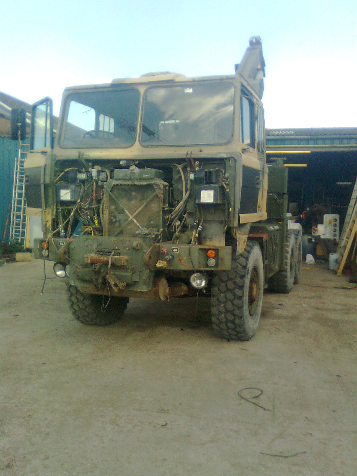
Bit of back ground to this project. This truck came as a trade in for my last project the Scammell drops that i converted to a recovery vehicle. To be fair i was a bit upset when it arrived with the condition of it but have got over it now and i think it has the makings of a fantastic truck bearing in mind it will have to work for a living not just be a show piece. Bearing this in mind it will not be rebuilt to the same spec as when in army use as a lot of features on army vehicles dont work well in civillian life. Hence i will be able to do some modifications to it that i would not dare to do if it had been a pristine vehicle when it arrived. I have absolutly no history of it or ID apart from the chassis number i dont even have the cast note for it or even if there is one. Maybe someone on here could enlighten me where it has served. Painted on it are large Vs are these specific to anything in particular then there is that sand the like of which i have never come across. I do how ever have a little info on the cab i have fitted. while looking through the cab i found a shipping note. It says Batus winter sailing QM(t) Batus JSCS Ashchurch MV Hurst Piont 32KE51 Montreal Marchwood 17/10/10
-
A cab was found along with the props and a few other bits I needed and put them on. This was not a fantastic cab but certainly better than the one I had. It looked as though it had been started on for a complete rebuild having had a lot of new parts fitted passenger seat heater boxes door shells clutch slave etc all have manufacturer’s labels on. The down side was the gauges and most of the dash was missing and one windscreen was broken. Anyway we put this cab on and we had enough bits to start her up again try her out and confirm that the truck had the bulk of what it needed e.g. enough gears high and low range a clutch that worked. A road test was out of the question as up to now it only has front brakes and one of these has a sticking cross shaft but I am a little more confident we can make a good working truck out of her. Next came the bit I was dreading most did the back end work. I fitted the two relief valves that where missing put 30 gallons of oil. Then started her up and engaged the PTO releasing the clutch oil spurt out all over. Fortunately this was only a loose return pipe to the tank but it proved the pump was putting pressure out. Second attempt I looked for leaks and all seemed ok so gingerly I pulled a handle at random after an age the O/s leg went down so I pushed it and sure enough after stuttering a bit it came back up. Slowly I worked all the levers and with the exception of the fold on the bottom boom and a bad oil leak on extend in and out bottom boom.

-
Like i said if they are any good to anyone there here


