BenHawkins
-
Posts
861 -
Joined
-
Last visited
-
Days Won
3
Content Type
Profiles
Forums
Gallery
Blogs
Events
Articles
Store
Downloads
Everything posted by BenHawkins
-
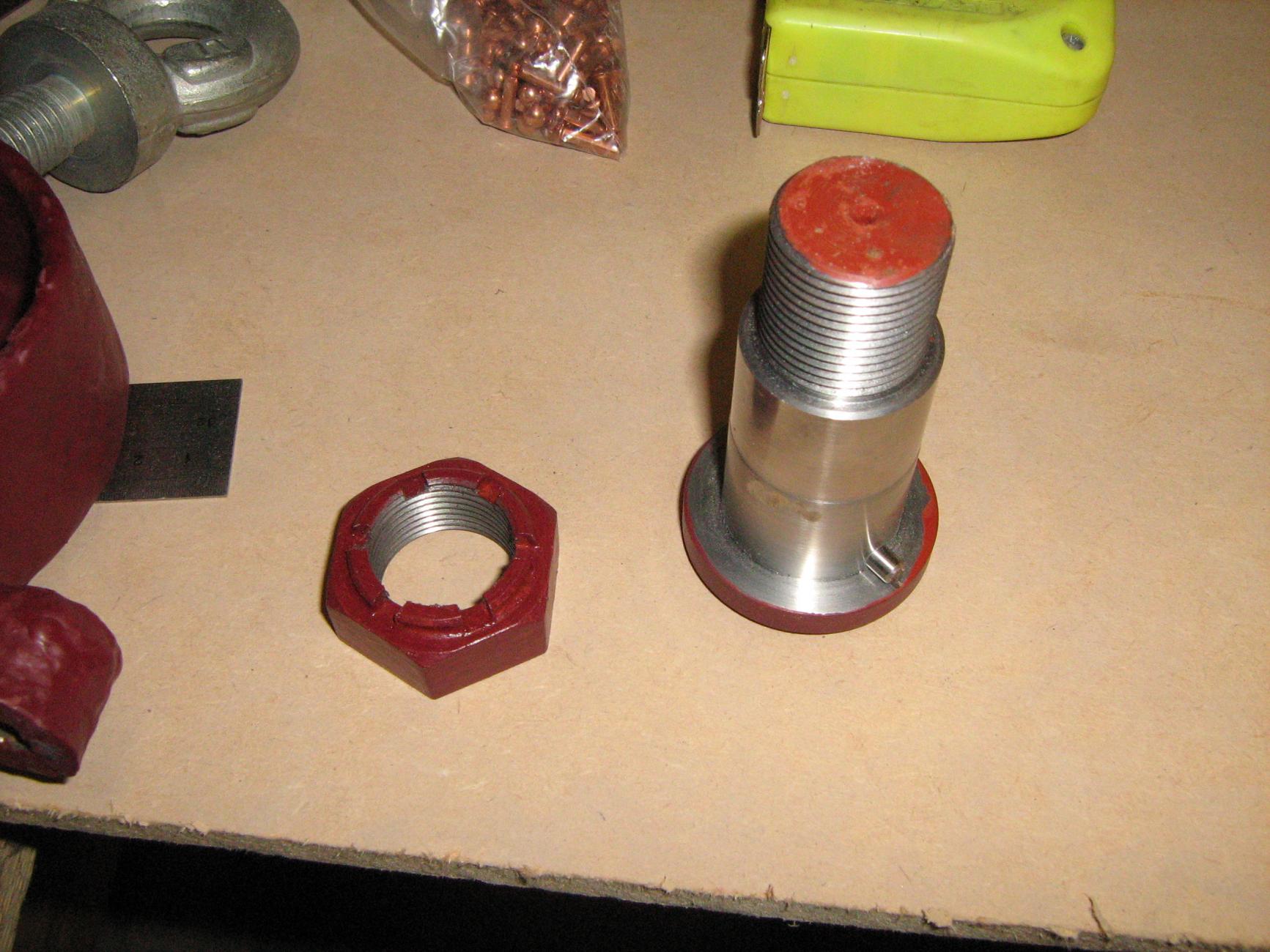
The big job for this weekend was to strip the front axle down. It took a selection of tools to remove the hub caps as the bolts were no longer hexagonal. There was plenty of lubricant in the hubs so they were well protected from water. I had to use a big socket to get the king pin nuts off. Unusually I realised it was a good idea to do this before removing the wheels!


-
As this engine was originally fitted to a generating set the starting handle does not come out past the radiator. I started by stripping down the assembly. I glued some bits of MDF together for a pattern for the longer housing. It still needs the ribs fitting before it goes to the foundry along with the tappet pattern.


-
I made a very simple puller for the tappets from some scrap I found under the bench. Then used it to extract the tappets from the crankcase. A roller runs in the slot, but in most cases they are broken off above the slot. One had been replaced with a bronze one but most are cast iron. I stuck some bits of MDF together and turned them in the lathe to make a pattern. Then painted it up. I decided it would be easier to machine them with the hole filled in so have not made a core box. It is only a 20mm bore so there will not be much wastage and they would probably cost more with the hole in. I will machine some of the flange away to make them into the left or right hand version.


-
Great work!
-
We are very impressed with the lamps. Metal spinning is on my list of things to try again!
-
The commercial motor archive is pretty good. When I am in America I am always amazed by how much is available on google books. However I think the UK copyright laws prevent it from being accessed here.
-
Richard, Thank you for the information you have sent to me in the past. The more we know the better our work on these vehicles can be! Ben
-
I am always looking in the local hedges and skips; surprising what you can find. Thanks for the advert Richard. I really love the adverts in Commercial motor, there are a few pre WWI loose magazines I have managed to purchase but the bound editions are out of my price range. The archive online is great for the articles but they have not included the adverts. Hopefully a bit more progress this weekend. I would like to get the front wheels off so I am in a position to get new rubber on all the wheels in by the summer.
-
Thanks Steve, it is great to be back at it after my two year break.
-
The sump cleaned up well. As did the timing cover. When searching the spare parts department I found a Dennis fan hub that fits nicely in the gap between the engine and radiator. I will need to make a carrier and also fit new blades. The pulley is missing from the engine but should be easy to make.


-
We removed the valve caps so the valves could be extracted from the cylinder blocks and after being marked up put to one side to be thoroughly examined later. I could then lift off the cylinder blocks. The gudgeon pins are retained by an forth "piston ring", two of these are broken so I will need to make a new pair. The bores look fairly good although I have not attempted to measure them yet. The bore is a nominal 75mm with a 110mm stroke (1940cc) and a nominal power output of 14hp. Next job will be to remove the camshaft to get access to the broken cam followers.


-
I had a few distractions this week so not as much progress as hoped. Having marked up where the steering column outer tube was bent I warmed it up with an oxy-acetylene torch and pushed it back into shape. Followed by masking the parts up and blasting them prior to painting. Hopefully reassemble in the next few days.


-
I also warmed up the laser cut footstep brackets to bend them and gave them a coat of paint. They will live on the shelf for a while so I don't bruise my shins on them too often. Cross drilling all the false frame bolts and split pinning was a bit tedious this week. I removed the mounting bolts that were rusted into the gearbox and when lining it up in the chassis realised two of the false frame bolts need to be countersunk to clear the gearbox body.


-
Between sessions hammering at the exhaust manifold I started to look at the steering box. It is off a slightly later Dennis lorry and has also had the column bent at some time. Having been outside most of its life I was worried about the condition of the internals but the oil had protected them. After the first clean it all seems in quite good condition I will clean up the casings this week and have a go at straightening the tube. The shaft is hardly bent and probably serviceable.


-
Each evening this week I have been stripping parts off the engine. The exhaust manifold has eight quite long studs so the rust on those was really difficult to break. I started by splitting all the nuts off; nuts are easy to replace. Then each night I applied some heat and bashed it will a dead blow mallet. Obviously plenty of penetrating oil as well. It started to move on Friday evening (so a crack was just visible at the gaskets) and finally came off this evening. The inlet manifold, starting handle and timing cover came off easily. A little more work to do before removing the cylinder blocks.


-
If a few broken guides are all I have to contend with I will be a very lucky man!
-
Hiding in the oil were a number of pieces of broken bronze. Further investigation showed they were from the cam roller followers. This photo does not show them well but does show the general condition of the interior of the engine. These are slotted bushes that prevent the roller follower from rotating. They were probably broken by a mechanic that was a little heavy handed when adjusting the tappets (possibly only using one spanner). These guides could not be driven out because the cam shaft is in the way. I will have to strip down the timing case to remove the cam shaft and I think it would make sense to remove the cylinder blocks at the same time to make sure nothing else is wrong. With the rest of the weekend we loosely fitted a selection of parts to make sure everything went together. Quite a promising start to the project.


-
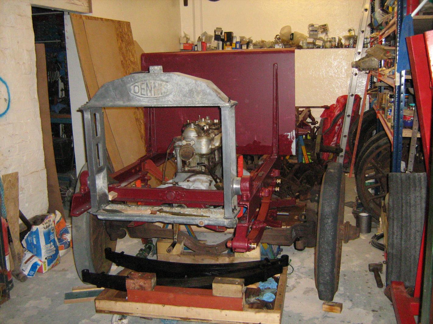
The brackets for the false frame that carry the engine and gearbox were finished in the week along with manufacturing the pivot pin and nut. I had some friends over for the weekend for a birthday party. It has given the project a bit of a boost. After fitting the false frame it was decided the best place to drain the oil from the engine was in the chassis. The valves and seats were examined; they need some cutting and regrinding to sort them out. There was a little water in the very thick oil so the next obvious step was to take off the sump for a look.


-
The tyres look great, I will have to decide if I can cope with driving slowly enough for polyurethane on mine.
-
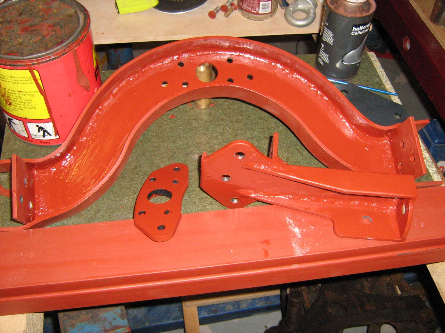
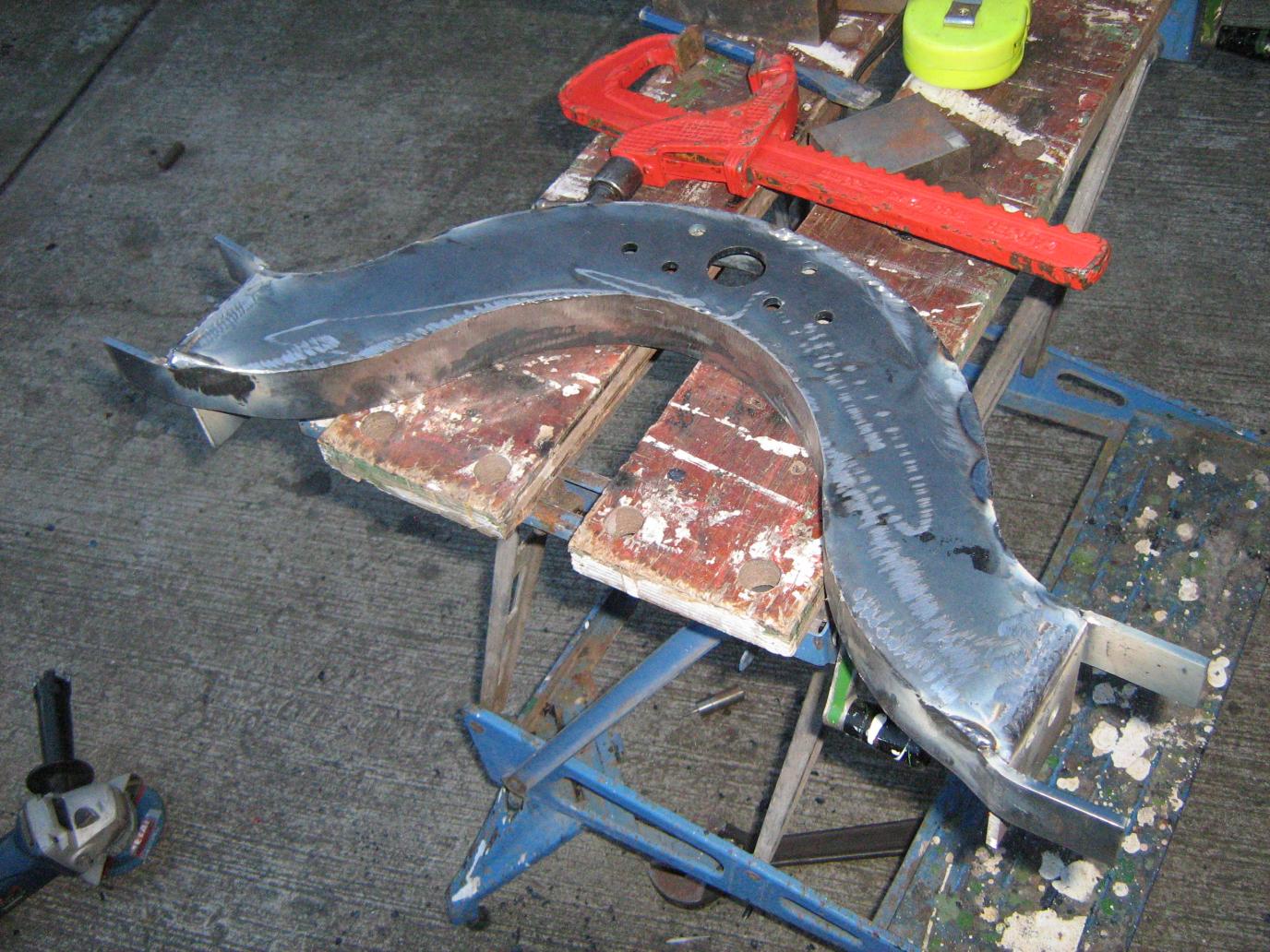
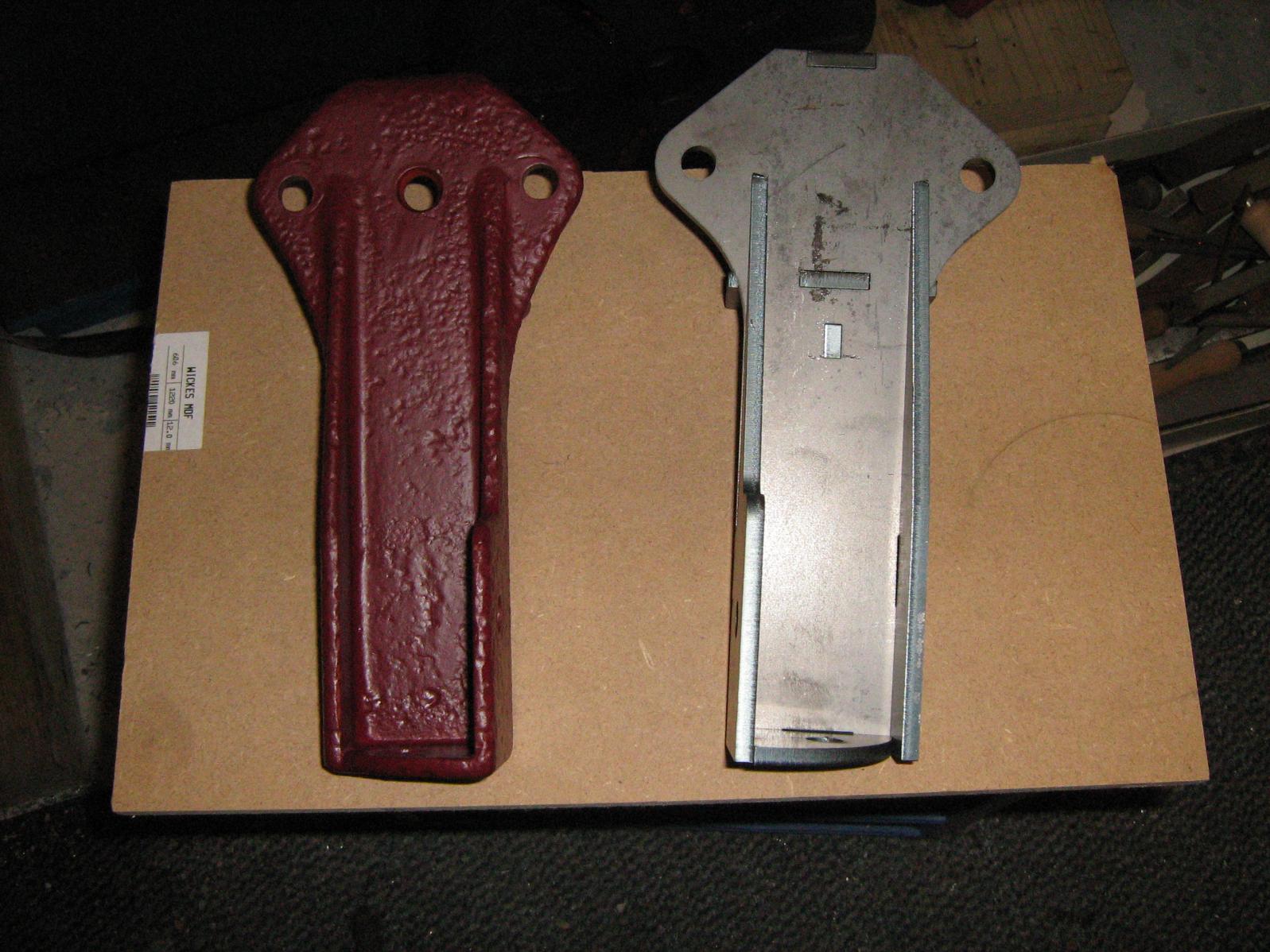
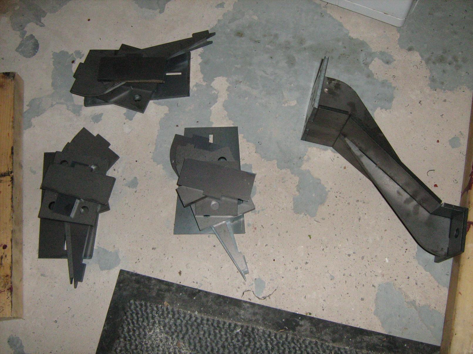
Thanks, it is great to be making some lorry progress again after two years of house/garage building. They say a change is as good as a rest! The front wavy bracket I think was originally a steel pressing 3/16" thick. I opted for 5mm S275 steel for this application. The welds obviously give it a slightly lower fatigue strength than the originals, but for the use it will get I really don't think this will be a problem. The other brackets were originally "blackheart malleable cast iron" when production first started and later went to steel casting. I think for this chassis date they were probably steel. Here I opted for 6mm S275 in place of the original 1/4". I think the fabrications probably have comparable properties to the original castings. I quite like pattern making but I don't currently have a supplier for steel castings and for small quantities the fabrication route does lead to much faster progress.
-
Tacking the flange and bending at approximately 2" intervals. And the finished fabrication. Just requiring a little bit of tidying up.

-
And a similar setup for the side brackets I have a little bit of welding to do this weekend.
-
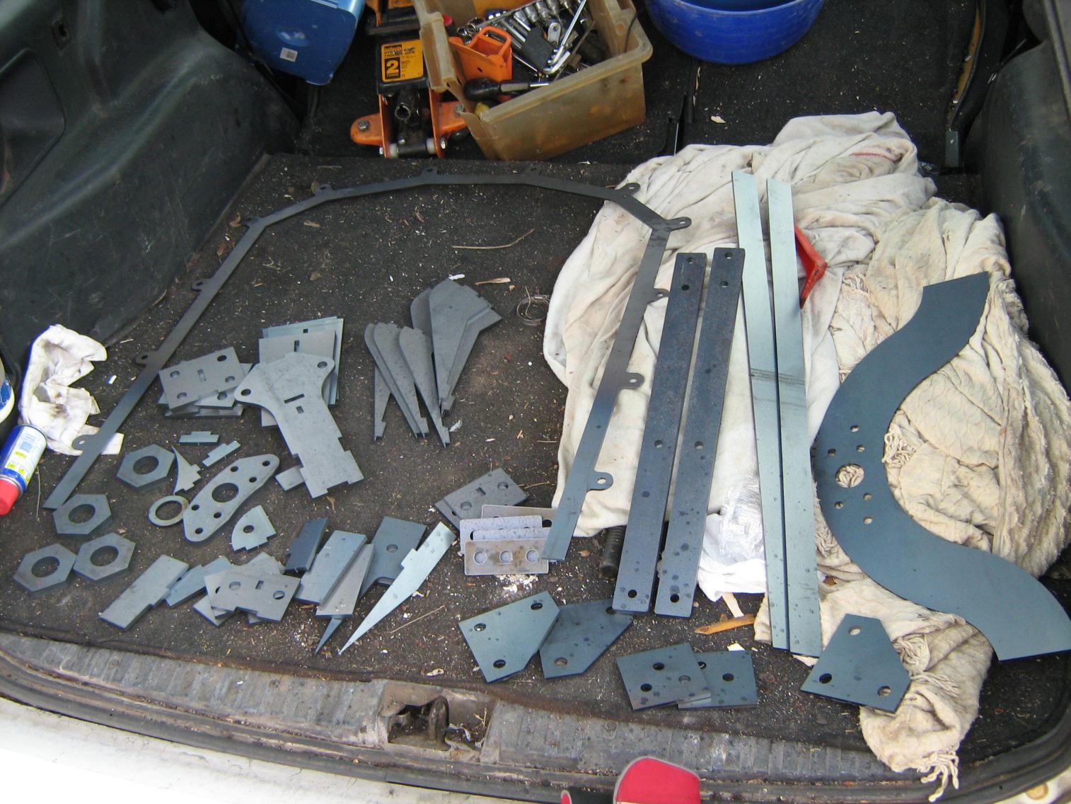
Thanks for all the information and adverts for UBAS. I sent some drawings to the laser cutters before Christmas and picked them up today. They have a minimum order charge of 60 pounds so I have to group quite a few things together. The engine and gearbox mount on two 3" channels mounted off the main chassis by two bracket and the back, a pivot at the front and two additional brackets at each side. Most of this was removed when it was being used as a trailer. This is the new laser cut pivot being turned down on my little lathe. I have one original rear bracket and had interlocking pieces of steel cut to match.

-
I have not done much work on this one recently. However whilst visiting a second hand machinery dealers to kit out the new workshop I came across this gear hob. New old stock never unwrapped from the original wax. It is marked up 6DP 29 Deg INC PA. This is the older standard pressure angle (14.5 degrees) as opposed to the "modern" 20 degrees. Just right to make the gears for this model and manufactured on 1-3-1919. Not quite as old as the vehicle but close. I need to commit to which engine to fit in the near future. All the nearly complete (later) engines I have come across sit on top of the chassis with the crankshaft axis level with the top of the rails. The original engine would fit between the chassis rails and the crankshaft axis was level with the bottom of the chassis rails. If I fit a later engine it would not fit under the original bonnet height. It would be really nice to make the bonnet and radiator this year and make it look like a vehicle but deciding on the engine governs the pattern making for the gearbox and radiator. The only work that does not need a decision on the engine is finishing off the handbrake. Does anyone know of a White and Poppe engine with four separate cylinder blocks sitting at the back of a shed somewhere?


-
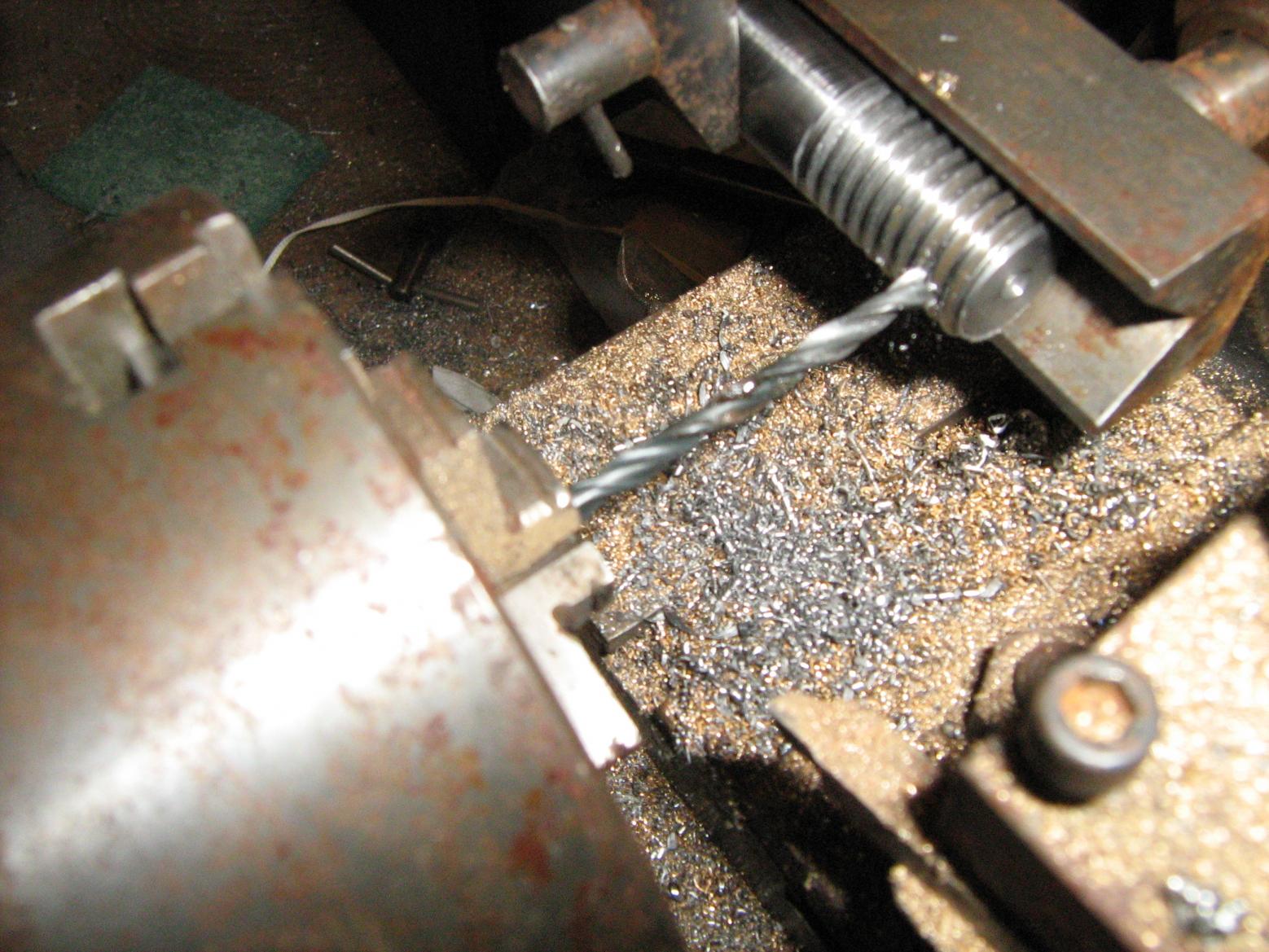
I have been making more shackle pins. A fairly simple but time consuming job. Turning to diameter and thread cutting (1/2" Gas or BSPF and 5/8 BSW) Then parting off, facing and chamfering the greaser end. Drill the grease hole. Drill for anti-rotation dowel and grease outlet hole through to central hole. Drill the split pin hole. And finally filing a grease groove The original drawings (held by the Surrey History Centre) show they were made from "UBAS" steel. This was a trademark of Flathers steels of Sheffield. It is described in period literature as an "Acid Open Hearth Steel" and was suitable for case hardening. UBAS was used quite extensively by Dennis, does anyone have more information on it?