


BenHawkins
-
Posts
861 -
Joined
-
Last visited
-
Days Won
3
Content Type
Profiles
Forums
Gallery
Blogs
Events
Articles
Store
Downloads
Everything posted by BenHawkins
-
We have been away on holiday so no progress for a whole week! But with the good weather forecast we decided to bring all the back axle bits out into the yard where there is a bit more space. We started by cleaning up all the surfaces and then fitted the new felt seals to the back wheels. The axle was jacked up to approximately the right height then the axle tubes were smeared with oil. The steel thrust washer could then be lubricated prior to fitting.


-
I then bored out all the tappet plungers to size. Followed by cutting a circumferential oil control groove on the inside with a different boring bar. Turning the High Speed Steel tool through 90 degrees and winding it through by hand allowed me to cut the grooves that return the oil back to the crankcase. The tool was just aligned by eye as the exact position is not critical. A milling machine was used to cut the slot for the roller. There is still a bit of work to finish shaping the flange and then repeat these operations five times for the other broken tappets!


-
A selection of felt seals have arrived from Hardy and Hanson. I filed notches in the bulkhead mounting holes. Dennis fitted a lot of metalwork this way, using coach bolts with three of the corners filed off the square. So I did the same using a Grover spring washer under the square nut. I have very limited stocks of Grover washers so will have to be quite selective about where I fit them (unless anyone knows of spare stocks). I then trimmed the side plates to fit around the dash irons and drilled them to fit the holes in the chassis. So I am now able to measure for the bonnet.


-
Yes, originally it was just the cast iron shoes pressing on the cast iron drums. I have driven a few vehicles without linings and they work reasonably well. Although I like to keep things to the original specification I am happy to improve the brakes a little given I had a set of shoes modified to take linings already. Ben
-
The back axle and wheels are nearly ready for assembly. I need new felt seals and a day of good weather so I can get it all out in the yard to slide the wheels on. So I am back thinking about the engine and have been machining the tappet sleeves again this week. I started by roughing the one end. Then turned them around finishing the other end to final dimensions. Then finished the top end and transferred them to the milling machine to profile the flange. I set the zero on the x and z axis to suit the rotary table. For machining I would the x axis to the zero I had set then rotated 180 degrees before proceeding in the x axis. There is still quite a lot of work to do on these but at least I have made a good start and have the six replacements to this stage. I have been thinking about the broken rings that retain the gudgeon pin. From the top there are three conventional rings then a groove for oil control. The end of the gudgeon pin is slotted and is a floating fit in the piston. A ring then restrains the gudgeon pin; this ring if compressed into the piston groove does not close up so it plays no part in compression. As all these gudgeon pin retaining rings are broken it is difficult to know if they should be sprung out like a compression ring or sprung in (like an external circlip). The replacement rings should be fairly easy to make from cast iron as they do not need to end up circular when closed up after cutting the ring. But will they all break again? Presumably they are broken by the gudgeon pin binding up in the little end when there is poor lubrication. If the broken bits of ring could cause damage to the bores would it be better to leave them out and fit bronze buttons to the ends of the gudgeon pins?


-
Then came counter boring for the rivets. I found a Morse taper shank counterbore but as the two shoes are riveted together they are a bit of a pain to fit on my machines. I decided to machine the start of the taper to parallel so I could get it in the battery drill. It should still work in the machines if required. The shoes did not originally have linings and where they have been drilled they come through on the radius of the casting making the whole riveting process quite difficult and requiring extra long rivets (thankfully these were available from Bruce Pickles). Each rivet needed to be a different length. Luckily I had Sarah to help by holding the shoes whilst I hammered (but never once hit her fingers, so she will probably help again in future). Then came shaping some oak blocks that fit between the springs and the axle. Nothing too complicated just some sawing, drilling chiselling and sanding. They have now had a coat of varnish.


-
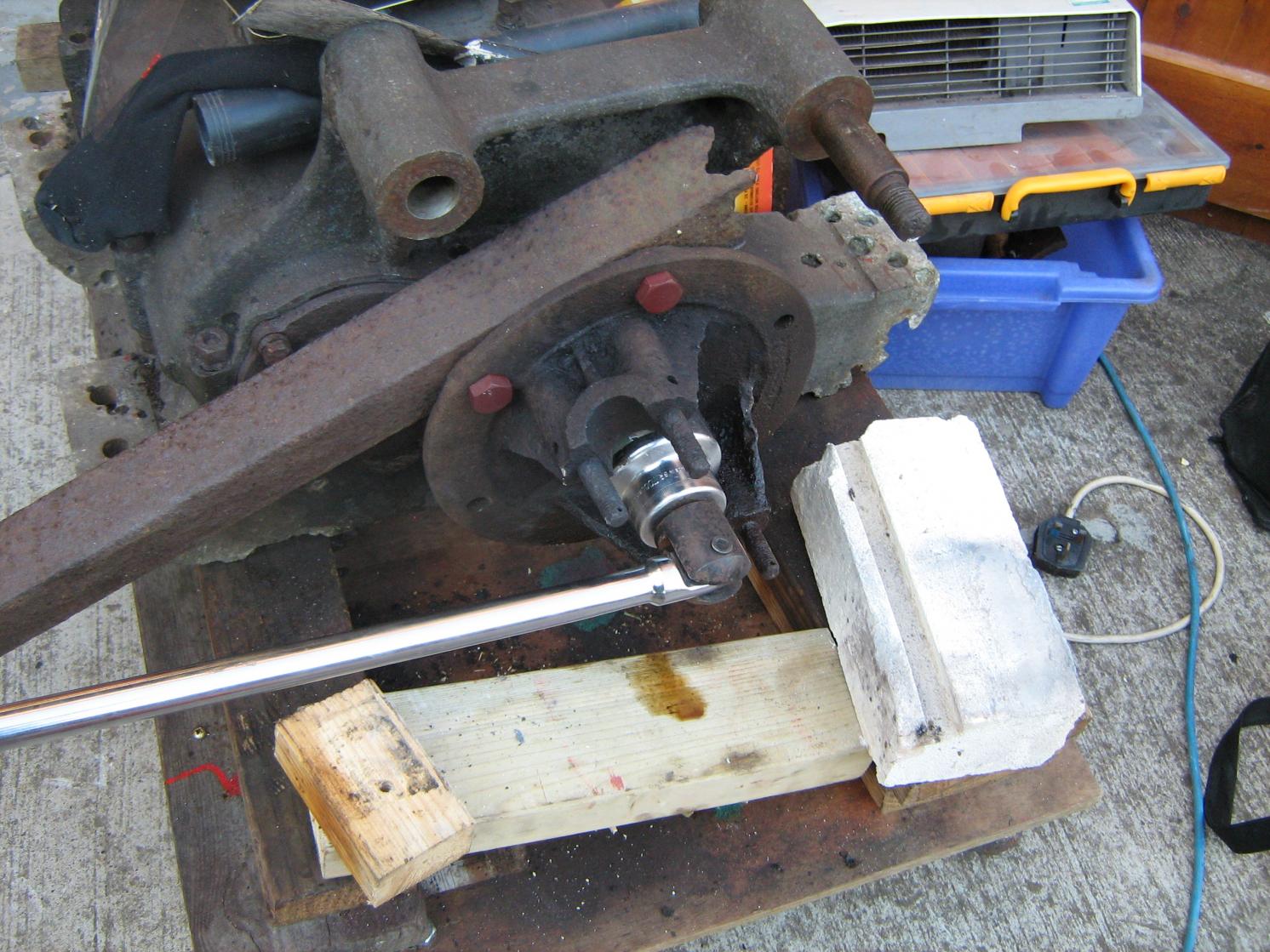
I have sent off the drawing of second gear to get some quotes. I will then decide if both parts of third need replacing; these will be more expensive as there are splines etc. I ground a tool to 55 degrees and cut the threads in the 12 nut blanks I made last week. Then with a little bit of adjustment to the bolts (I damaged some of the threads getting them out) and drums (opening up the notch) the drums could be fitted to the wheels. I clamped up the brake linings and drilled through using a battery drill.


-
Thank you for your thoughts and the supplier suggestions. I had a good look on the shelf and found a similar looking gear from a newer Dennis gearbox: But unfortunately when I checked it is one tooth short and 5DP. I then tried the appropriate involute cutter against the existing gear. These cutters allow you to make gears with a good approximation to the correct tooth form; a set consists of 8 cutters. A number 1 cutter allows you to cut a 135 tooth gear to a rack and you select the other numbers for the number of teeth on the gear. This one is a number 3 (for 35 to 54 teeth) that I picked up at some point. But despite being the correct number for 37 teeth it does not fit well because it is for 14.5 degrees pressure angle and the gear appears to be 20 degree pressure angle. Early involute gears were usually 14.5 degree pressure angle but at around this time a 20 degree pressure angle found on modern gears was starting to be adopted. At 20 degrees the gear teeth are stronger.


-
I think I would worry that with the limited amount of tooth left on second gear there would be a risk if snapping a lump off and that doing damage to something else. I have counted 37 teeth and this ties in with the parts book that states it is part number 754/4 and a replacement costs £1.13s; perhaps I will call Dennis in the morning and see if they have one . As it happens the drawing for this part has survived. Originally made from KE 805 with Reinecker teeth hardened and ground the material was later changed to "3035 Brinell 451-500 heat treated". The gearbox is a slightly later design than the chassis (and the parts book I am referencing) so there may have been further changes. I think I may have a suitable 6dp cutter to check against the gear for pressure angle.
-
I have not checked but I believe 6DP with a 20 degree pressure angle for this one.
-
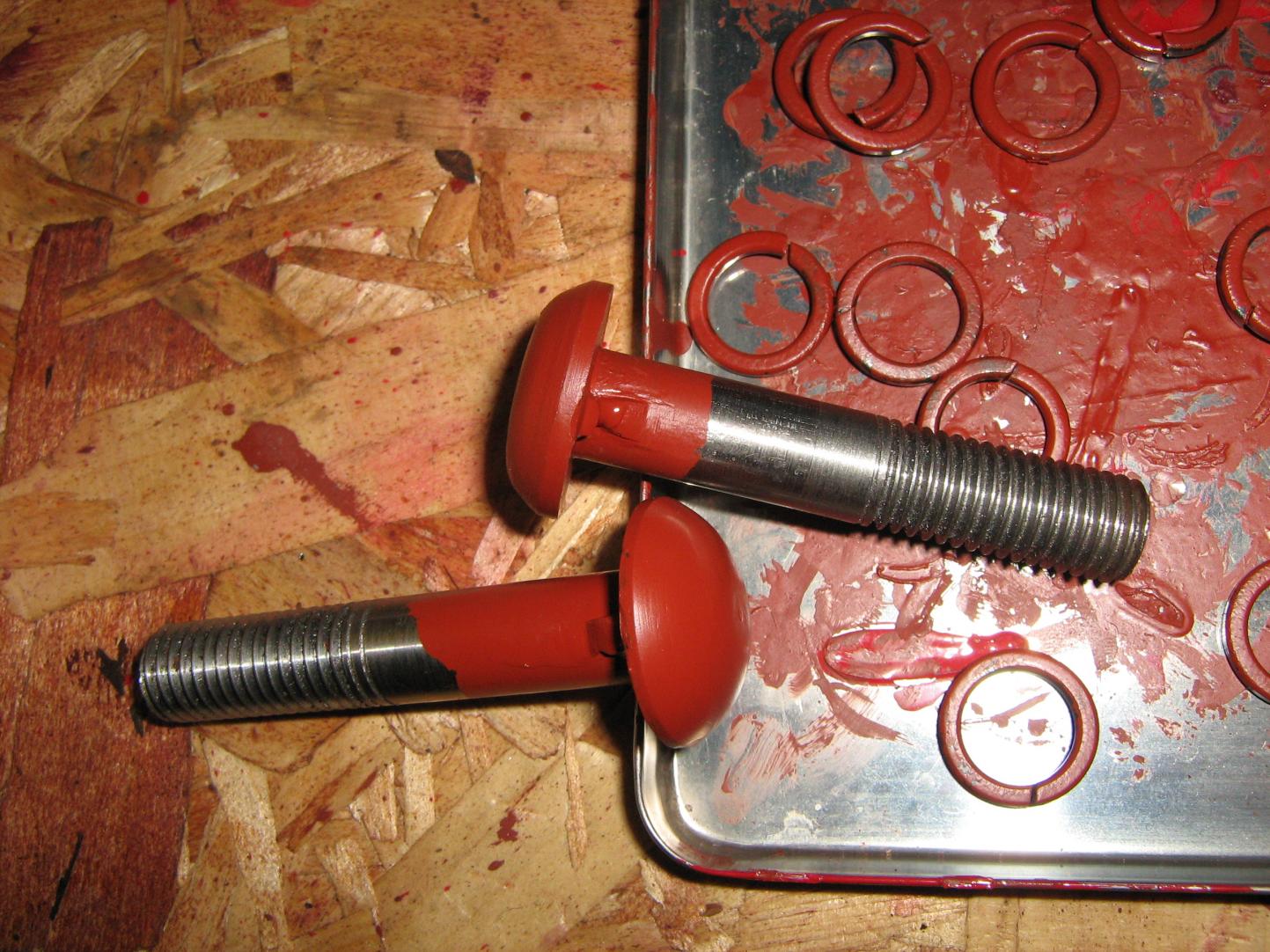
Thanks for the messages of support. I know it was probably a little excessive to make nuts and bolts to match the originals when off the shelf hex bolts would have been perfectly satisfactory from a mechanical point of view. I am fairly confident the thread is 55 degrees; which I think rules out Thury :undecided:. So I have managed to remove the last couple of bolts holding the gearbox casings together. It does not look like any water has managed to find it's way in, so it is generally in quite good condition. I would appreciate peoples opinions on the condition of the gears. I think the third gear pair is probably acceptable but that the larger of the second gear pair really needs replacing.

-
There was just enough weekend left to have another look at the gearbox. I bolted on an old bit of angle from a fence to stop the brake hub from rotating. Then got it as warm as I dared with a propane torch. Unfortunately I still couldn't get it to move and I feared I would damage something if I applied any more heat or force. So I decided to split the nut as I should be able to make a replacement fairly easily. I started by drilling at the base of one of the slots. Then split it with a chisel. It was then an easy job to unwind the nut. I was then surprised that the hub was not rusted onto the splines and was relatively easy to remove.


-
I managed to damage two bolts so they would be unusable. I machined replacements then welded on the protrusion to prevent them rotating. They are a non standard thread 1/2" x 14tpi whitworth form. I also need 12 new nuts as none of the originals are hexagonal any more. I roughed them out but still need to sort out suitable tooling to put in the thread. I filed up the welds and painted the bolts. Then bolted and split pinned the other axle journal.


-
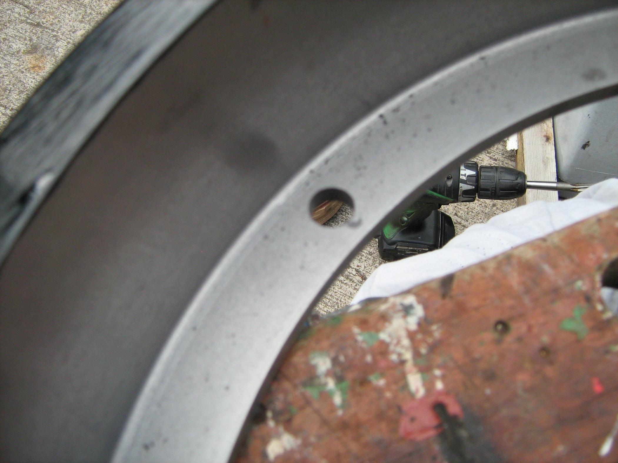
During the week I spend some time machining the castings for the tappet guides. On Saturday I worked on the brake drums. The drums are a snug fit on the flange of the wheel so I clamped them up and drilled through the existing holes in the wheels. Each hole required a small angled notch to stop the bolt rotating. I started by centre punching and starting a small hole of the correct diameter. I then filed these out to suit the bolts.


-
I removed the manifold (combined for inlet and exhaust) and the direction of rotation is the same as the original White and Poppe (if the flywheel end is at the back in the conventional way for a road vehicle).
-
If I end up using the engine in a lorry the intention would be to replace the current flywheel with a cone clutch version and remove the reversing box (replacing it with a starting handle arrangement). This is easier said than done as the gearbox sump is continuous to the gearbox and that is actually where the oil is stored (due to the inclination of the engine for marine use). When I turned it over before I bought it I convinced myself it was of the correct rotation but I should probably check that again once I get the manifold off and can be more certain of which valves are which. As Andy says I will probably get carried away and build a boat around it
-
Kermath were American marine engine manufacturers. This is the Model 16, introduced in 1915. It developed 16hp at 800rpm, 18hp at 1000rpm and 20hp at 1200rpm. They were advertised for other applications such as tractors (without the integrated gearbox). This particular engine was sold through Gaines Gears in Brentwood and marketed as the Gaines Kermath.
-
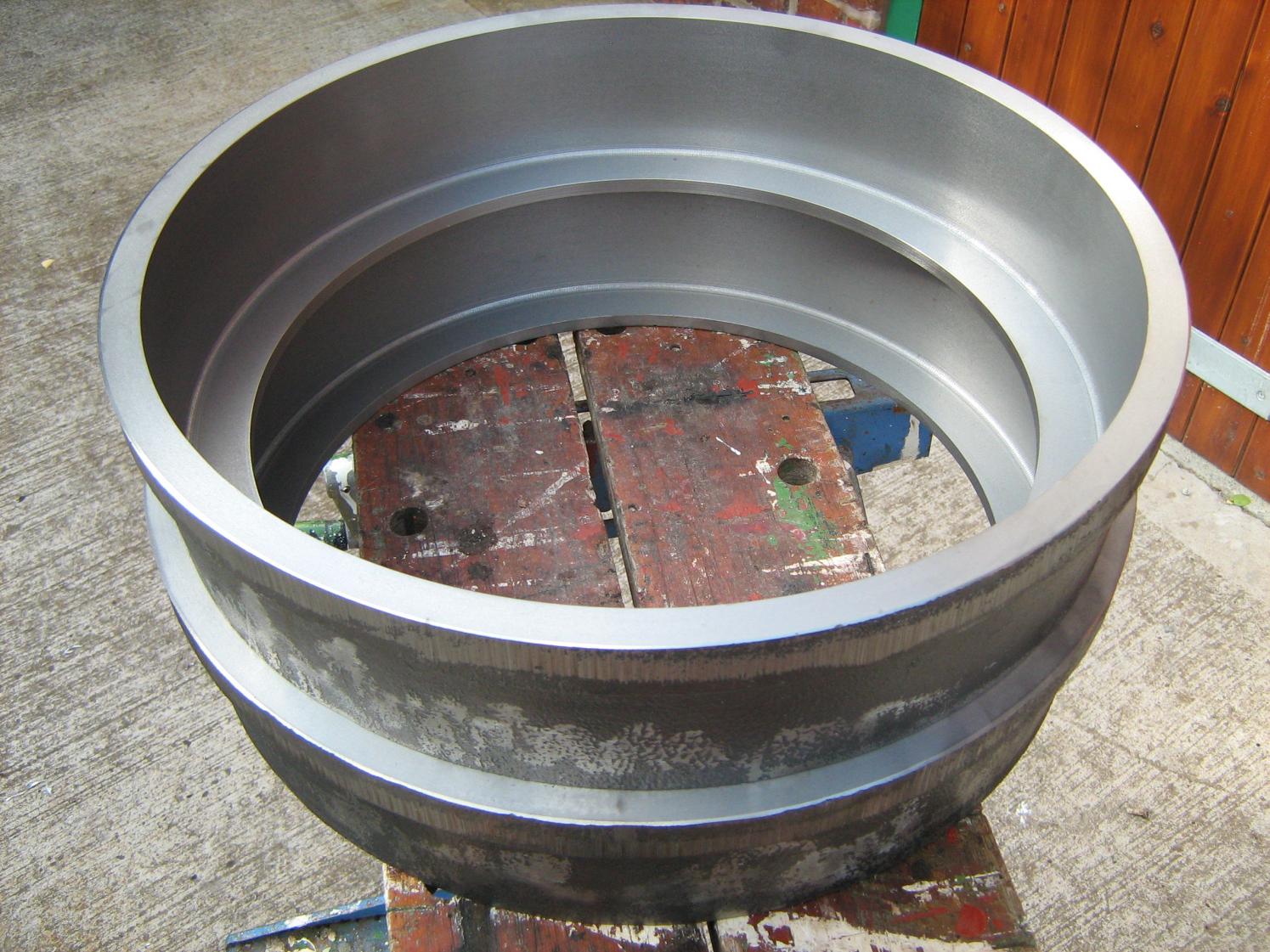
I had to go to China for a couple of weeks to install some machines so that slowed progress quite dramatically. However a local machine shop has machined the brake drums for me whilst I was away. I still need to drill the mounting holes. The brake linings have arrived so when some long rivets are delivered they can be fitted. We also dropped the front axle off at the Severn Valley Railway boiler shop so they can replace the missing rivet for me.

-
Today we went down to Surrey and picked up an engine: It is a Kermath marine engine and will require some modification to enable it to fit to this chassis. However it was not expensive and means I have something to fit if no more of the original model turns up. There is quite serious frost damage to one of the cylinder blocks that will need repair. But on a positive note it is free to rotate and has compression.


-
It has been another week spent mostly on painting. Today we went to the Banbury Run for a nice day off looking at veteran motorcycles. The only real progress was refitting the axle journals. These connect the back axle to the springs but allow the axle to rotate within the journals. We still need to reline the brake shoes and repeat the whole procedure for the other side. Once those jobs are done and the brake drums are machined we can think about fitting the back axle and wheels, it will then feel like we have made real progress!

-
I was busy with other things at the weekend so there was a little less progress than usual. The rear axle journals were blasted and primed. I picked up the brake drums from the foundry. They are too big to fit my lathe so I will need to get someone else to machine them. And gave the wheels a coat of paint.


-
This week seems to have been mostly taken up by painting wheels. However I did manage to make the other side lamp bracket (and even managed to make it the mirror image of the first), then gave them a quick blast and a coat of primer and undercoat. We spent this afternoon freeing off the remaining bolts in the gearbox. The only one that is still tight is the transmission brake nut. I need to drill some angle or bar (to fit to the holes in the flange) to react against the torque applied by a socket on the nut.


-
After sanding and roughly shaping some mounting bosses.

-
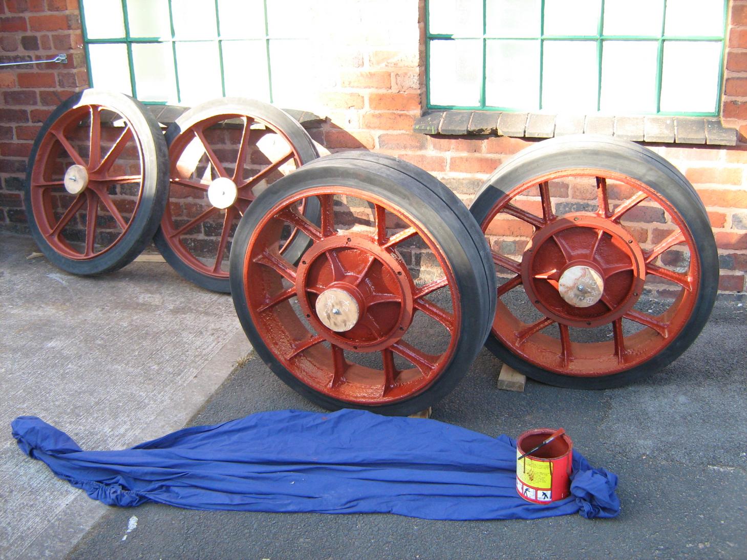
The wheels are back from the rubber company: They also blasted and primed them. I gave one another thorough coat of primer before the paint ran out. Then the first coat of undercoat. They take a while to paint so will keep me busy for some time.

-
After marking up the hole needed in the bulkhead I used a hole saw to put in 1" holes at the corners. Then cut between the holes with an angle grinder. I then made the first of the side lamp brackets, first welding a bar to a previously laser cut flange then bending it free hand with the application of a little heat and cutting a slot to fit the spade. Then it was just a case of welding the spade on. Finally dressing it back with an angle grinder.


