


.JPG.ce5d5173b9120e587cf914646a67c75d.JPG)
Pete Ashby
-
Posts
1,682 -
Joined
-
Last visited
-
Days Won
8
Content Type
Profiles
Forums
Gallery
Blogs
Events
Articles
Store
Downloads
Posts posted by Pete Ashby
-
-
Thanks Pete - I've found out that CAV made different types. The Dingo unit is as Richard describes.
Hope all is well with you - haven't seen you for a few years !!
Regards,
David.
Not come across metal cased CAV units before, is that an armoured thing ?.
I'm good thank you David still plenty of the toys in the barn to play with. No we have not met for a few years, I do occasionally emerge out off the mists of the west as my son still lives in Wantage and we do a couple of shows a year and a few sales to keep my hand in

regards
Pete
-
Interesting, a little difficult to see clearly but I think the 3 ton 6x4 may be an AEC, pictures of these trucks in service are not common.
Pete
-
Can anyone please tell me the original factory colour of the casing for the WW2 CAV voltage control box (or Control Board as described in parts books).
In this case the CAV 141-1 as fitted to a Dingo.
I'm presuming black but I've seen some painted silver as the rest of the engine bay and green as the rest of the vehicle. Does anyone have first hand knowledge of an unused,straight from the stores example ?
Thanks.
David.
Good evening David, the CAV units I have for the Leyland are NoS CVC and fuse box they are made from a material that is similar to Bakerlite but more fibrous and brittle the colour is dull black.
Regards
Pete
-
Sad news another early collector and restorer gone. I knew George back in the days of the early Normady tours and the Hurne airport and Weymouth shows that he and the Dorset area used to host back in the late 1970's and early 1980's.
Condolences to the family
Pete
-
Sorry didnt phrase the question very - imeant would using eggshell paint protect the metal as good as gloss?
Im guessing/assuming that because its halfway bewtween matt and gloss that it wont be as good a barrier as gloss but better than matt?
However you know what they say about assuming........
A(am curious as looking to repaint my jeep totally after completeing a few panel welds and wanna get it right - top coat will be an eggshell)
What we are saying is that a gloss coat over a good quality undercoat will act as a barrier to what ever top coat you choose to use
Pete
-
Jules,
The jeep shown, was ex-British Army (with an interesting history after demob, that's another story) and it still had some of the original footman loops for the web straps, so side screens had been fitted in service at some point.
The jeep in the workshop at the moment is ex British army and it also has the footman loops at 45' by the door openings and the turn buckle at the front to take British side screens.
One thing for sure.......... they are coming off and the holes are getting welded shut......... too much of a liability in modern traffic also I could never keep the damn things done up tight when I had a set always working lose and flapping about like a demented carrier bag.
If you want to use side screens go to one of the canvass suppliers and get a set that fit properly and provide some semblance of visibility.
Pete
-
That is a very fine looking car Keith,
my Farther spent the summer of 1940 driving a similar car to yours for his OC Capt Gregson 7th Royal Norfolk's.
His duty was to take his OC around the various fortifications and airfields in Norfolk and Suffolk that the Norfolk's were guarding.
Apparently after dinner in a local pub Gregson would go to sleep in the back and give my Dad a chance to get his foot down he always claimed that the Humber would cruise comfortably at 70mph all day long.
Regards
Pete
-
Seem to think the Bernard Venners had one once.
Your memory serves you right Richard, Bernard had one for many years, did at least one trip to Normandy and may have done more. I seem to remember that he sold the truck some years ago, I'm seeing someone at the weekend who may know what happened to it
...I'll ask.Pete
-
You may get a result if you speak to Ant or Mike at AMD four wheel drive in Merrylees.
01530230023.
Plenty of choice with those guys, at not (by current standards) unreasonable prices.
Pete
-
Hi All
I know these exist, indeed i have a rough set dated 1945, the rear section is windowless and the 'doors' are glazed with that plexi glass, but look as if they are designed to fold down, rather than swing open like the modern replacements of these days.
My question is, what evidence is there of these actually being used on British jeeps in ww2 ? and if so, as the set i have are a brown/khaki colour, and presuamably the US jeeps imported to this country for us to use, came with US top canvas which is much darker in colour, there would have been a distinctive differance in colours ?
What can anyone tell us about the US/British canvas provided for British Jeeps ?
Any photographs would help too.
Cheers
Jules
Jules
get yourself a copy of 'the wartime jeep 1941 to 1945 in British service' by Gavin Birch ISBN 0-9534470-9-X lots of photos in here of the Humber side screens is use.
I had a set years ago and they were a liability then let alone in modern traffic. They are designed to hinge outwards using the windscreen pillar lift dots as the hinge point........horrible things, my advice to is to keep them in your garage as a curiosity and don't use them.
Pete
-
I'm very close to spraying my Humber now, and i have some good original B/W photos to copy cammo patterns from.
I'm going for the 'Dark Earth' and British Green.
However the original photos look as if the finish was dead matt ? and if i do this what implications may i find further down the line ?
Cheers
Jules
This question has appeared in various forms on HMVF and other MV forums over the years.
Thoughts differ in the detail but the general consensus ( and I subscribe to this) is that flat paint is porous and over time will lead to spot corrosion particularly if the metal surface has been blast cleaned.
However this is not an issue provided you use a good quality primer and my personal choice is then a good hard gloss undercoat before application of a matt top coat. I suggest you do a search on this forum and take a balanced look at the suggestions put forward.
Something to be aware of, flat paint will show grease or finger marks as you can see that if you look at period photos (even straight out of the factory).
Pete
-
Just picked up on this thread Pete , you are doing a cracking job. I watch with interest.
Thank you Rick, as I say at the start of this blog progress is steady by any standard as I tend to work on the Retriever in fits and starts depending what else is in the workshop, so it may take a while yet.
Work required to finish the frame/cab is rebuild the rear axle, finish the rebuild of the radiator and install it then make a set of cab hood bows from a set of originals that I have been kindly leant. After that rebuild the wings....... not an easy task as they are more fresh air than steel....... I may weaken and get a new set made.....if I can afford it.
After that it's the easy bit to build a reproduction workshop body from plans and drawings I produced using an original MK 3 body.
Pete :nut::nut:
-
This post is a bit more positive than the previous one here the cab is rebuilt using the original parts as patterns.

Here the scuttle has been bolted on to provide a reference point to work away from. The floorboards and steel well sections in the floor have been replaced, the steel floor under the pedals has been replicated and the drives seat box is in place again to act as a reference point.

In this shot the cab side frames have been fabricated, the rear steel centre panel has been replace and the two composite steel and plywood rear panels are in place. For some time I pondered how I was going to reproduce the angle iron radius sections that form the entrance to drivers and mates cab side originaly these would have been hot rolled.
By chance I was poking about in the scrap pile behind the workshop when I found some old iron bed frames......guess what the radius, the size and gauge were just what I needed a few minutes with the disc cutter and hey presto two perfectly replicated rolled iron frames.

The drivers seat box has been rebuilt using a mix of original and new wood. As with all British trucks of this period the comforts provided for the crew were to say the least minimal as you can see the seating is nothing more than a wooden box on top of which a thin horse hair cushion is strapped.

The wooden cab sides are in position waiting for the outer and inner 18 gauge metal skins to be made and the mates seat box has been rebuilt
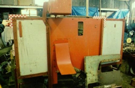
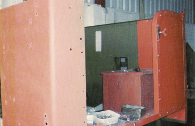
This is a back view of the cab showing the replaced steel centre section and the two composite rear panels

The cab panels and scuttle have been removed so that the frame can be painted before reassembly, this photo clearly shows the sub frame construction of the cab and how the whole construction depends on the scuttle to hold it all together at the front.
This view is from the mates side, the cab sides have been replaced. The scuttle has been stripped repaired where required and painted in undercoat

The cab is now finished apart from fitting out with brackets, clips and turn buckles and is mounted on the frame.
-
I think we have got on the wrong track here. This engine is not fitted with rings as we know on Austin, Bedford and GMC, it appears there are rings fitted to the gaskets for No's 1 and 4 exhaust ports, but the centre siamese gasket for 2 and 3 does not appear to have rings. I am wondering if the gaskets being used are from different sources and centre one is thinner and thus not pulling up tight. Also I would be very surprised if the block was bowed at this point.
Ah....... that would explain why I couldn't see any rings in the post war manual I've got.
You may have a point there Richard with miss matched gaskets, or it may be that the integral rings are binding either way I would still go through the process of 'dry' fitting and trying with feelers as I said before do the simple stuff first.
Pete
-
Ps the black scorches are on the block top of the centre two ports
Hmm OK try my suggestion first before we all start getting gloomy about having to reface the block, the simple cheap options are always the ones to try first.......easy to say...... difficult when it's your motor I know.
Pete
-
Oh I know that Pete, Hanno and I go way back, far back enough to remember when I was taller than him!
and I thought he had always been that tall :-D:-D
Pete
-
I can confirm Adrian that Hanno speaks the language better than the majority of the indigenous population
Pete
-
Thanks for the replies all now is clear -
Im now using a new manifold so has had none of the surface removed in theory
Only thing is from memory the locating rings appear to be fixed to the gaskets but I will double check when the new set arrive
If lucky I will get it done this weekend if not the week after
Thanksa again
Your welcome, what I should have added is run the engine up to operating temperature slowly then let it idle for 10 min or so, then turn off and quickly re-torque the manifold nuts to same torque setting and in the same pattern as previously used before the manifold cools, you will probably pull all of them up by a quarter turn.
Pete
-
A yes, nudge, nudge, wink, wink, know what you mean!

There you go Hanno, Good old English humour again
I really think you are becoming a confirmed Anglo file :cool2:Pete
-
Im sorry for sounding so thick - but can u just clarify what u mean by bottoming out?
ArQe the gaskets / rings possibly too thick?
Yes I am getting leaking gasses and blackening where the gasket is being blown away
Nobody sounds thick when they ask a question, the thick ones don't know when to ask :undecided:
What Richard, Howard and I are suggesting is that your port locating rings are too long since you have had your manifold faced off, this is not an issue with the old GO Devil engine as it does not use port locators but your third generation jeep motor apparently does. If you look inside your manifold ports you may see a shoulder inside as I'm not familiar with your particular block you may find a shoulder cast in the exhaust port of the block. the ring sits on the shoulder, having said that I have come across some types of engine where the locator ring is just a push fit and wedges in as the port narrows either way it doesn't matter which The ring length is designed for a factory spec manifold yours is now shorter by how ever much was removed, do you know how much was taken off to clear?.
The result of this is the port locator ring length needs to be reduced by the same amount to maintain the original fit parameters usually this isn't an issue as the port locators are not a machine fit however if yours were tight to begin with or your manifold has had a lot of material removed to clear then it can be an issue.
Iv'e had a look in my post war manuals and I have to say I can't see the port rings but if yours is fitted with them perhaps they were a modification? and not covered by my information.
I suggest you may try the following:
1. Clean the manifold and block faces to remove all traces of the old gasket and any sealant you used make sure you do not scratch the machined faces, use something like a wide blade flat paint scraper to do this. I use a bearing riffler but you don't need to find one of these, just use the paint scrapper without digging it into the surface. Finish off by a very quick light rub in tight circular motions with some 400 grade wet and dry dipped in paraffin then wipe both surfaces with a petrol soaked rag to clean up.
If you are going to leave this overnight give the surfaces a rub over with a clean oily rag to prevent corrosion.
2. Put your port locators into the ports
3. Without the gasket install the manifold and just pinch up the nuts do not torque them at this stage
4. Using a set of feelers see if you can get a 2 thou gauge between the block face and the manifold at any point on a new block and manifold this should not be possible, with yours you may find that you can so try the next size up until you can’t get a gauge in. take a note of the size of gauge.
5. Take the manifold off and remove the locator rings and measure them using a calliper (you can digital ones off e- bay for a very few pounds)
6. Take piece of glass or a mirror and tape a piece of wet and dry 250 or something similar to it add a bit of soapy water to your wet and dry and rub the rings down in a circular motion you are aiming to remove the same amount as you measured with your feeler gauge plus I would suggest 30 thou for expansion. Wash the rings in paraffin to remove any grit.
7. Refit the rings and manifold without the gasket and pinch up as before
re measure the gap it should have closed up to under 2 thou. If not you may have a block face distortion
8. Assuming every thing is fine disassemble put a very thin smear of Holts exhaust paste on both surfaces of the gasket and reassemble the whole thing just pinching up the nuts. Start in the middle and working out either side equally to the ends.
9. Torque the nuts from the middle out to ends one on each side at a time to equalise the force your torque settings should be in the range 29 to 35 ftlbs
All sounds long winded but it will only take an hour to do the whole thing. You don't say where the burn marks are are they on the manifold face, the block face or both faces ?
Pete
-
Good point Pete. I have had to make narrower ones to suit on a few Bedford and Austin engines after the manifold was faced.
Yep been there done that Richard, I think over the years I've had more trouble with those little suckers on six cylinder engines than anything else. The temptation is to just chuck them in the workshop bin but their function is two fold,
1. to locate the ports accurately
2. prevent burn through of the gasket material under high load conditions
I also suspect that they help to normalise the heating/cooling stress on long single cast manifolds......... although the number of banana shaped GMC and Bedford manifolds I seen/changed/owned makes me wonder if this is not just wishful thinking on my part :-(
Pete
-
With regards the gaskets , do the metal rings insert into engine block or the manifold ? Manual says insert into exhaust port which I'm assuming is the engine block -
They are a v tight fit into engine block but just drop into manifold
Thanks
One thing occurs to me are you sure your port inserts are not bottoming out in either the block or manifold I had that problem once with a GMC in this case they were French repros and bottomed out in block and held the manifold off the block face by about 4 thou, impossible to see with a new gasket but held the manifold off the block so it would not compress the gasket enough under torque to form a compression seal. Consequently it would run for a few hours until the exhaust gasses burnt through the gap and gasket and then start to leak again. When you take the manifold off again check for burn/track marks on the block face and or manifold.
It may explain why you cracked the first manifold. The simple answer is to put the rings on a flat plate with some wet and dry and rub then down until they locate but do not prevent the manifold block interface without the gasket in place.
Pete
-
How much engine, drivetrain and bodywork do these Chevs share with GMC CCKWs? if any
Cheers, Richard
Without going into precise detail (for which you really need both parts books) it would be fair to say that commonality is restricted to instrumentation and some but not all electrical components, although visually there are similarities they really are two different trucks.
Pete
-
I will now have a picture of Richard doing a Poor Man's NASA in my head all day! :-D The Dodge has two curved slots for the distributor timing, one for 'Coarse' the other for 'Fine'. I used all the fine adjustment to get back to where I wanted. I've read the Octane adjustments in the manual, but was there a master list or such of the settings, or was it wiggle till works?
Your best bet Tony is to be confident that your static timing is correct then adjust by ear (or if you feel a bit flush buy a vacuum gauge). This will give you optimum settings across the power range and will take into account the ware in your specific engine components and variations in burn rate depending on the type of fuel you are using.
I have to say I've never used a vacuum gauge but am considering investing in one, I know some who claim amazing feats of timing and divinity using them........ any one out there wish to comment ? .
Pete


WW2 British CAV Electrical Equipment - Control Board.
in British Vehicles
Posted
Thank you Richard full answer as expected, interesting that you quote the QLR aux gen control unit as being a similar example as I've noticed on factory photos of Mk3 Machinery bodies that are fitted with switch gear for machines a similar sized item mounted on the front board with the isolators. I never could work out what it was, I now wonder if it was one of these units.
Pete