


.JPG.ce5d5173b9120e587cf914646a67c75d.JPG)
Pete Ashby
-
Posts
1,686 -
Joined
-
Last visited
-
Days Won
8
Content Type
Profiles
Forums
Gallery
Blogs
Events
Articles
Store
Downloads
Posts posted by Pete Ashby
-
-
She's a beauty and a credit to you sir. Truly a lovely machine. Excellent read and info. Thanks for sharing . . .til the next one!!! Lol
Thank you Hoseman much appreciated, actually you are nearer the truth than you may think with your last comment
 , if you look closely in some of the photos you will see another jeep body stacked on it's side in the workshop the rest of it is in the another barn. This is slat grill MB frame No 720 build date second week of November 1941 this belongs to my son David who is currently collecting parts from all over the world before he starts on it.
 regards
Pete
-
PETE l have enjoyed watching 24 YH 46 being restored thank you for that HOW ever l was surprised that you said DEEPCUT had no record of this jeep when l collected the key cards a list was compiled of the postwar numbers GIVEN TO WARTIME B VEHICLES that we had these were titled KEY CARD No 2 not to be confused with the KEY CARD FORM 419B
Which relate to vehicles that came into service after 1950 as you can see from 09 YH 21 TO 99 YH 99 the attached list all numbers for jeeps in the YH range were present when the list was updated in 2002 at a Beverley so at least a reference to your jeep would be in the documents at that time if any were missing it would have been noted AND if it arrived after the listed had been updated a note in ink would be made so the next time it was up dated it will have been included in the new list
regards wally
Thank you Wally I'm pleased you enjoyed the blog.
Regarding the key card, I sent my £25 and a covering letter to Deepcut in August 2013 and heard nothing from them......not a problem as others on this forum have commented on the time taken to get a return by the time it got to Feb this year I thought I might give them a prod so phoned up and after being passed around several people was told that if they had not responded then no record existed, again not too surprised as I know from other research that war time records can be a bit hit and miss and indeed Deepcut warn of this possibility on their non refundable fee so I put it down to worth a try but bad luck.
Regards
Pete
-
Very nice jeep Simon it's obvious she's well loved and cared for just looking at your photos I can see a number of similar features to mine which are of British origin. Your jeep must have been one of the last out of service at 1960 mine was sold of in November 1957, very nice to see you kept the script body, as you have seen sadly mine got lost along the way somewhere. I did initially toy with the idea of putting a repro script body on however the composite ACM2 tub was so good and formed part of the vehicles history so in the end it was a no brainier. I have tried to present the jeep in a form that it may have appeared in the early spring of 1944 after a class 1 British rebuild ready for the invasion but before the field order to apply invasion markings was issued.
As for the coincidence of our identical census numbers..........what can I say........perhaps some one on here can do the maths at the chance of this happening when two people who have never met or seen each others vehicles arrive at exactly the same seven number set using different principles.... you and I should really dot he lottery together
Regards
Pete
-
To finish a few shots taken 72 years to the week after this GPW rolled off the line.
400 miles on the clock now and so far no issues, the tappets on No1 are a bit noisier than I'd like but they can wait until we get 500 miles on the clock.

.JPG.d17855f883f5f2f712cc2291ccaf02e8.JPG)
.JPG.f04adb6e3d1416857d5a40184a51f079.JPG)
.jpg.678798e1230c8d3de1e071a4e911a715.jpg)
-
The build was completed and it was time to start thinking about markings.
During the restoration it had become clear that this vehicle had been operated by the British so I wanted to reflect that with the new markings. Some research turned up the following: Ford frame No 14768 was produced between the 8th and 10th of April 1942 possibly in the Louisville Ford plant either at the end of the first contract or start of the second. 725 of these GPW’s were withdrawn from issue to US forces and diverted to the British and sent to the UK along with 175 MB’s. The GPW’s were given the census numbers M4938144-M4938868. Rubbing down the bonnet I found the remains of a census numbers on both sides on top of the OD, the left hand side clearly started with an M but no other numbers were clear enough to be sure of, on the right side again the prefix M then nothing to be sure of and then clearly at the end of the bonnet the numbers 625. So given the frame number and the above information I decided to mark the jeep with census number M4938625

And that Simon is how I came up with the number so how did you arrive at yours ?
Is it the correct number for the vehicle?... no way of telling….Deepcut did not have a record card for 24-YH-46 so the evidence is at best circumstantial but it just might just be part of those 725 units diverted to the British… I like to think so.
Another discovery was on the grill apron inside the engine bay the remains of ‘antifreeze’ stencil was uncovered along with the numbers 10.43 which I took to be the date so this went back on after re-painting.

The unit markings are for the 1st Battalion Suffolk Regiment 3rd Infantry Division

-
Time to bolt back on a few detail parts;
this is a close up of the trailer socket the jeep came in with this fitted, it's a late war or possibly just post war version with a Bakelite end cap I believe the early war version was a brass cap (see a thread on HMVF by David Belcher). The convoy light switch is a NoS item that I've had tucked away for just such an occasion, the mounting holes lined up exactly with the holes drilled in the cross member. The number plate light is post war but does not look out of place.

Here is the convoy light again the jeep arrived with this in place. The light shield is not original and appears to have been locally fabricated but the bracket and light holder are correct.

These are the data plates I commissioned from Dataplates4u.com these are excellent reproductions using the correct style of stamping font, data information presentation and plate material depending on the month and year of production very highly recommended. I chose to use the frame and most of the running gear DoD for my plate details so correct for them but wrong for the body but consistent with a British army rebuild scenario in late 43 early 44.

-
Here are some close ups of the head lights I was talking about in the previous post, not exactly right for the original sealed beam glass pattern but near enough I think so as not to look out of place.

here is the rear light conversion for indicators, this is a common conversion that a lot of people use for US tail lights and I think it works well both in looks and functionality. I convert in the inside of the light housings to take bulbs and I will be experimenting with LED clusters when I find time, I know some people on here have done this already but I've not tried it yet so will be interested to see how they perform.

Here is a couple of close ups of the installed wiring.....not much to see really on a jeep


The shielded lighting loom harness along the wing is from expandable nylon over sheaf available in a range of sizes I spray it sliver and Bobs your uncle.
-
I make my own wiring harnesses using cotton covered pvc sheathed wire. These are available from a number of vintage suppliers in a huge range of colours traces and gauges. Get the manual check the wire colour trace number and gauge against the suppliers catalogue then measure the run with a piece of string and add at least a meter extra and make up a shopping list all up it comes to about £75 in 2013 prices.
I use soldered terminal rings terminals and correct style rubber tube insulators to replicate the original harness. When Iv'e done vehicles that need a woven loom cover I make up the runs tape the turnouts and leave the turnouts over long and without terminals and send it all away with instructions and drawings to be over braided. Jeeps however have looms that were insulation tape wrapped so I can do the whole job in house. I used to use Lasovic black tape, now I use Self Amalgamating black tape this is magic stuff and every tool box should have a roll, it has a world of 'get you home' uses Google it if you've never come across it.
Back to the jeep, doing the wiring is always a pleasant task you can sit down at the bench with a mug of tea and the radio and soldering iron on and just pootle on. I incorporate indicator feeds into the harness as I go so nothing shows. I convert the blackout lights at the front and rear to indicators and the switch I hide under the drivers hip pad. The relay light goes into the body gusset upright by the drives left leg, bit fiddly but I like it as unless you really look for it nothing shows. Side lights are in the head light lens, I use head light lenses that have the glass integral to the lens and take standard fittings for head light bulbs and plug in side light bulbs the glass is very similar to the original sealed beam units and the whole thing fits perfectly into the original head light bucket. The different sized woven tar impregnated over sheafing can be bought by the meter again from vintage wiring suppliers for not a lot of money and makes a nice finish around the headlights and tail lights. Correct gauge battery cable for 6v (gauge 0 ) comes from the same supplies by the meter it's PVC covered but I over cover this with the woven tar sheaf so it looks like the original then I solder on the terminals.
OK so wiring is done and installed and all working and all the dash instruments are in I had to replace the speedo so chose to use one of the very good reproduction ones on the market. I fitted the second type long needle version which would be correct for the frame date but wrong for the body. I'm happy with this as it keeps the theme of mix and match from a wartime rebuild.......and for no other reason than I like the look of the long needle speedo:-)

The windscreen was fitted this is a repro of the later pattern with rifle holder brackets but an original inner, it took a bit of tweaking to get it to sit right and fit the hood correctly but it came good in the end.
And now it looked like this;


-
Now that is truly amazing Simon, I think you and I should do the lottery this Saturday !! :wow:, at the end of this blog I'll talk about how I chose the markings for this jeep and it wasn't via the route you arrived at yours.
Regards
Pete
-
Wings and grill on now things are starting to come together
Years ago a bought a job lot of the Bitumen impregnated cork welting for wings to body, grill to body from Walley Wheatly at Nordian Sevices, I'm down now to my last few rolls but it's the proper stuff and really makes a difference in terms of those irritating squeaks when driving.
To make fitting the welting an easy one man job I do the following, mark out the length required and cut then hold in place and mark the hole positions with a sharp pointed scribe. Take off the vehicle and use the appropriate sized wad punch to cut out the holes now I super glue one side of the welting onto the body or alternately onto the wing or grill, doesn't matter which, make sure the holes line up let it go off for a minute then you can use both hands to fit the wing or grill without any risk of the welting slipping out or getting misaligned.
So with a bit of fitting out inside the tub it now looked like this;


-
I left every thing for a couple of weeks to let the paint harden off and got on with some minor repairs to the top hat section on the drivers wing and then removal of paint from the wings, grill and bonnet and then my standard repaint sequence.
The wings are nicely marked on the top face with a script 'f' and are of the early pattern with no black out light holes so they may well be contemporary with the early frame, the grill has the indent in the middle of the top rail this came in mid 1942 to enable Ford and Willys bonnets to become interchangeable so is not contemporary with the frame and is not 'f' stamped the bonnet is 'f' stamped on the hinge and had the interesting detail of a small hole drilled just in from the leading edge on the center line. When I measured it the dimensions corespond exactly with the position specified in British standing orders for a pennant mount for Field Officers.......interesting feature but I have to say I have welded it shut as it will let the rain in.
It was now time to sling the body on the crane, push the frame underneath remove the steering wheel and undo the steering box mounting bolts and slide the frame forward while lowing away on the tub, engage the steering column in the foot well hole and lower and move the frame back carefully until everything lines up. Perhaps worth mentioning at this point I always wrap the column in masking paper so the paint don't get torn off during this operation.
This is my team fitting out the body prior to lifting

And this is what it looked after the strops were removed and the body bolted down


-
A little bit of welding on the drivers side panel and all the tin bashing is complete

Now it was down to removing the paint from the underside of the tub and preping for painting. 2 coats of 182 Zinc primer,
1 coat gloss grey 3 coats of Cromadex semi mat OD.
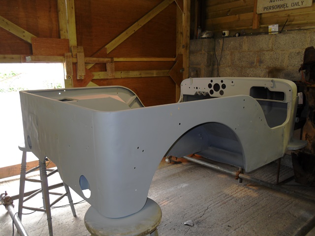
This photo shows the front half in gloss grey and the rear in Zn182 primer
The tub was turned over and the paint was removed from the upper surfaces.


Then it was on with the primer coat as before but this time a coat of spray primer filler was applied and lightly rubbed back this was to blend in the repairs.
The standard gloss coat of grey and three coats of OD


-
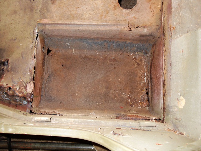
Now it was time to tackle the tank well the only option here was to cut out the old well and replace with a reproduction part.
Before I did any cutting I took accurate measurements made drawings and took photos of the tank position in the floor both inside and out of the tub also the depth at which it sits front and back relative to the floor. It is critical that the replacement is not too far to the right as the distance between the well and the outside face of the frame is very tight when the tub is installed.....too far right and it won't fit:(. Some people get over problem by doing this job with the tub on the frame.
I was careful to drill out spot welds where possible to enable the new sump to use the remaining flanges as datum points. I do all my straight cutting where necessary using ultra thin cutting discs in the grinder they give a 1.5mm width cut and are very easy and controllable to use.
The new tank well mounting flanges were drilled to enable plug welding and a dry run undertaken first to make sure every thing lined up and matched the drawings and measurements


-
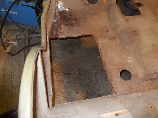
With all the extra holes welded shut it was time to look at the foot wells. The rotten bits were cut out, then thin card (the stuff you get in new shirts is ideal) is held up from underneath and the shape of the hole traced onto the card with felt pen. The patterns are then cut out and the shapes traced back onto new steel. These are then cut out and welded in using mig 0.6mm wire and universal Argashield cover gas. The whole lot is then dressed back flush with the power file and flap disk.
The top hat section that needed replacing were also cut off and replaced with new top hat section and treated hard wood fillers.


-
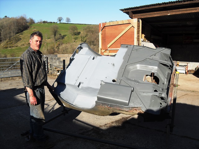
The first thing to do was to drag out my Heath Robinson body jig from the depths of the hay barn. I made this some time ago out of scaffold poles and clips with castors attached at the corners. It lets me move the body around the workshop and by using universal swivel clips on the up right posts I can rotate the body, very useful for welding and painting.
I decided to start by plug welding the extra holes in the sides of the tub using 0.6mm mig wire and universal Arga shield cover gas. I try to find a washer that is just a bit smaller than the hole to be filled then clamp this in position with a heavy duty copper heat sink at the rear then just tack weld round slowly letting the copper take the heat out of the body to avoid distortion. The weld and washer can then be dressed down using an air driven power file with 80 and 100 grade belts or rotary grit flap disc in the angle grinder.


Removing paint and gunk from the front of gusset leg I found the ACM2 body number clearly stamped, this is a very low number and it would appear from information received via the G503 forum that this was constructed during the first week of production for the composite body......that equates to the first week of January 1944.

These photos show some of the additional holes welded shut and dressed down


-
Thank you Bob,
yes there certainly are comparatively a lot of jeeps about, I think I saw an estimated figure on the G503 forum once that suggested around 5 to 6 thousand world wide but I'm not sure how accurate that figure would be.
-
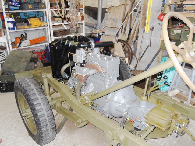
So that was the frame, springs, running gear, engine and transmission all back together and finished all that remained was to clean the the prop shafts, check for true, push out the old UJ's and refit new ones (making sure the Zerk...that's grease nipple in the Queens English... faces out) paint and fit in place.
Time for a test run of the engine :cool2:. The oil pump was packed with Vaseline before assembly and then if possible I always like to fill the main oil gallery via the gauge line using an old style 1 pint squirt can just before the first start. By doing this I find that a few revolutions with the ignition off will start to show pressure on the gauge. Hook up a hot wire onto the coil and second pull and away we go:-D. No matter how many times you've done it there is nothing like that first start to bring on a smile. Oil pressure was as per the book so after everything came up to temperature and the choke was off I adjusted the timing a tad then shut off and started on the body.
First job was to go round the tub and make a list of the jobs that would be required and then sit down with a mug of tea and draw up a simple plan (posh word for list) so that work could be done in the most time efficient manner.


-
Thank you Steve,
I've been at this sort of thing a long time now, but I should point out that I'm not a time served engineer like some of the guys on here. I learnt from my Father who was class 1 REME fitter in ww11 and have been lucky to call among my friends in the MVCG as it was then some very good professional motor engineers. I've also been lucky in that I've had the opportunity to own and work on a cross section of the Allied WW11 B vehicle list.
regards
Pete
-
I always like this part of any restoration as it's now that things start to come together and the vehicle takes shape, rather being a group of parts in the corner of the workshop.
First new tubes, flaps and tyres were fitted to the combat rims that had been previously checked for true and then painted and put aside for a couple of months to let the paint harden off. Then the rims were fitted to the frame and the whole assembly pushed under the crane to drop the engine and transmission in which had previously been bolted together as unit. New mounts for the engine and transmission were installed as it hung on the crane and then everything was lowered and bolted up loosely while still taking the weight on the crane to ensure alignment then it was lower away and tighten up fully. The re-cored radiator was then fitted and coupled up with new hoses I elected to use the later type hose and metal pipe rad hoses rather than the one piece rubber of the early design.


-
Andy thank you for coming back to this thread with your findings very interesting indeed with regard to the success of using the original generator on a 12 volt system.
Food for thought
Many thanks
Pete
-
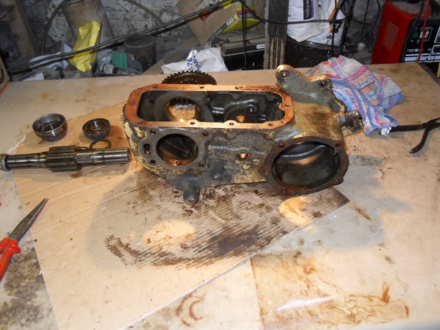
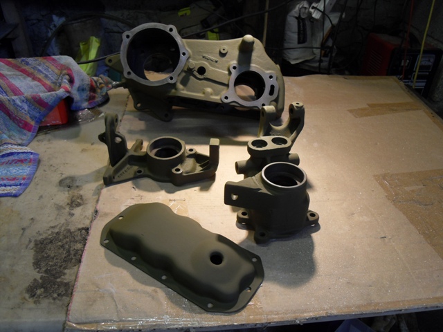
Continuing with the transmission theme the transfer case was next on the list for attention. All components were removed from the case and this was then examined for cracks and out of spec bearing and shaft openings, everything checked out well within spec. the gear teeth were in very good condition but there was some ware on the thrust washers so these were replaced along with all the bearings and seals.

-
So with the engine complete the next task was to tackle the dirt and grease encrusted transmission. All the gunk was removed from the outside of the cases to prevent contamination before the transfer and gear box where split and dealt with individually.
I looked at the gearbox first and this turned out to be a 1943 replacement which by this stage was not unexpected as the whole vehicle was showing classic signs of full British army overhaul.

However on the plus side the whole truck was very complete without the usual civilian additions/bodges and not suffering any WoF bolt ons.
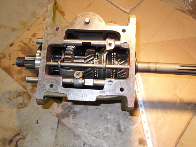
Back to the gearbox, dis assembly went well with nothing jammed or bent however when the bearing surfaces and thrust washers were measured against factory specs it soon became evident there was a lot of ware so a full rebuild was in order.
All the bearings were replaced along with the cluster gear which was out of spec on the bore and the shaft showed corresponding ware. 2nd gear had taken a real bashing and the syncro hub fingers and blocking rings had seen better days, probably why 2nd was in such a poor condition.
The case was good and not cracked and the bearing and cluster shaft bores where not worn and well within spec the bottom of the gear stick was in very good condition as was the selector gate so these were reused along with the selector rails.


As a matter of course I changed the detent rail springs and balls and with a new set of gaskets it was good to go with a new thrust washer and return spring.


I should add the fly wheel clutch surface was faced off before being installed on the engine and a new clutch disk and pressure plate fitted.
-
Next unit to be overhauled was the engine here are a couple of photos of the unit still installed
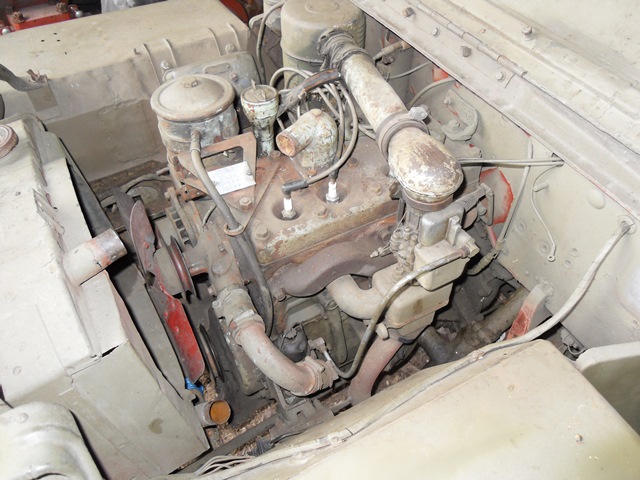

And here it is on the workshop floor awaiting cleaning and dis-assembly

and here with the head and oil sump removed
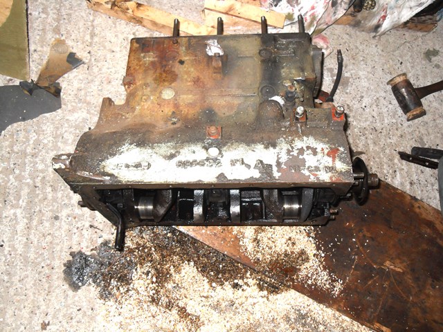
All components were measured against the factory specs for ware tolerance, if found to be with limits they were reused but if worn or any doubt existed components were replaced with new. The 1955 dated rebuild plate on the oil filter bracket stated Mains std, big ends std, bore +20 this was found to still be the case and although there was ware it was just on the limit of being OK indicating that since 1955 this engine had not done excessive mileage another plus:-)

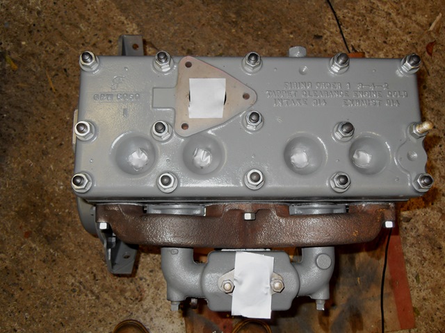
Close inspection of the block showed up a tiny crack radiating from the middle head bolt so the decision was made to send the block away for heat treating and fusion welding... expensive.... but but worth it in the long run. The block was then sent to my local engine machine shop, real old school. They polished and then cross cut the bores to maintain +20 and took -10 off the crank and big ends to clear, all in all not a bad result


The head was found to be slightly bowed in both directions but with some careful work by the machinist it milled flat without loosing too much under the water jacket. A good result as its an early Ford 'f' marked head contemporary with the DoD of the vehicle.

This is probably the appropriate point to fess up, you'll notice that the block is finished in Ford grey all very correct except it's not a Ford block it's a Wilson Foundry block as fitted to MB's........OH dear bit of a scam on my part:blush: actually maybe not and this is why. Apparently Ford had problems supplying block castings for the first 3 months of GPW production so Wilson empty bare blocks were supplied to the Ford plants who then installed ford and GPW components into the block and fitted their own heads and ancillaries and painted them grey. Every component inside the engine was of Ford manufacture including the early riveted and soldered drain hole on the sump however to be truthful, the casting code is wrong by a month and the construction stamp on the sump flange is out by two months on DoD the engine number is odd too as it's just stamped very faintly on the block pad a 16600 no MB or GPW prfix the engine was definitely in the truck in 1955 as the rebuild plate uses the same number. So is it a rebuild salad? very possibly is it an early factory fit? may be but it's close enough for me to feel happy painting it Ford grey.
The early f marked non vacuum ported inlet manifold was broken at the block lug so sadly I have fitted a Nos latter replacement however I kept the nice f marked exhaust after having it faced of with the new inlet manifold. The water pump was the early GPW type but I have had very limited luck when trying to repair old pumps so I opted for a late war pump fit and forget and pretend I can't see the heater take off plug..... I can and it irks me, but reliability is more comforting:angel:
So engine rebuilt with new mains @+10 new big ends @+10 new rings@+20 the piston skirts were fine and the ring belts well with tolerance so they were used again. 8 new valves, springs and adjusters, the tappets, cam, and valve guides were good to go, new cam shaft bearing, thrust plate and spring, new timing chain and rebuilt oil pump the distributor was fine so that just had points rotor and cap replaced and it ended up looking like this.
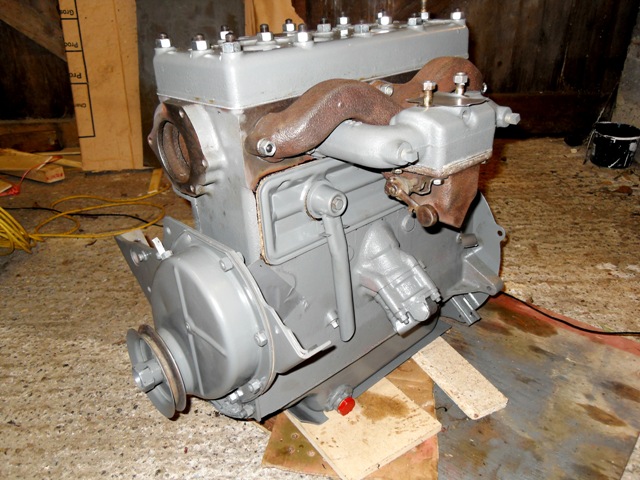
The carb was cleaned overhauled with a NoS kit and the throttle shaft and bushings replaced.

The bell housing had the following marking LV US/ORD G503 737108 this in 1" black letters on post war duck egg blue replacement engine colour

-
The next task was to examine the springs for cracked or broken leaves, worn spring eye bushes and worn shackle eyes. I had a mix of MB rears and GPW fronts all of the early pattern. The rear spring packs were in good shape and I decided to use them with new eye bushes even thought they were MB the decision for this will be explained later in the thread. The fronts were pretty flat and had seen some hard service so I decided to bite the bullet and replace them with a new set the chances of finding a NoS set of GPW early front springs was next to 0 so I decided to have a set made up by a company I have used before (Jones Spring Engineering Ltd from Darlaston no connection with the company except happy customer) these guys are very good and have the original specs to set the springs with the correct camber and load bearing capacity. Unfortunately they cannot supply the correct GPW spring clip but I'm happy with what they provide it's very close to an MB style and I'd rather have good springs that aren't 100% correct than original ones that are a danger.
New swinging shackles and bushes all round and they were ready to fit to the frame. Along with the rebuilt steering box, this had a new sector shaft, bushes and oil seals, the worm and races were in good usable condition

Time moves on.

.JPG.d17855f883f5f2f712cc2291ccaf02e8.JPG)
.JPG.f04adb6e3d1416857d5a40184a51f079.JPG)
.jpg.678798e1230c8d3de1e071a4e911a715.jpg)


Bedford mw fuel pump
in British Vehicles
Posted
Martin does the 28hp pump have an off set rather than parallel stud mounting flange ? I've got a NoS one on the shelf that is marked AC 'U Type' on the body and 4405 on the off set mounting flange, like all old diaphragm pumps it will not be ethanol safe but a modern kit would put that right.
Pete