


.JPG.ce5d5173b9120e587cf914646a67c75d.JPG)
Pete Ashby
-
Posts
1,686 -
Joined
-
Last visited
-
Days Won
8
Content Type
Profiles
Forums
Gallery
Blogs
Events
Articles
Store
Downloads
Posts posted by Pete Ashby
-
-
Barry, e-mail sent
regards
Pete
-
Baz PM me with your e-mail and I'll send you the photos with measurements attached
Pete
-
Ok i'll dig it out and take photos and measurements, I'll post here in the next day or two.
Pete
-
I can dig out an original from the store, the wood infill is the same for 12 and 11 cab this one is still in place on a screen frame I can photograph it and let you have dimensions if that would be useful
Pete
-
With the inner wing section fabricated and welded in position a degree of strength had been returned to the structure so I could turn my attention to the rear wing section which was completely missing. The problem here was that although the basic shape was relatively straight forward it has a shallow compound curve left to right and top to bottom and then a short sharp upward flare where it meets the main wing. The only way I could think of getting the upward flare to curve in three directions was to cut into the flare in a series of short cuts to provide relief to enable the double curve and upwards flare so it ended up looking like a fan. The inner edge is a wired rolled edge and I fabricated this using the method I described previously.

Once the whole piece had been welded to the main wing the cuts in the flare were welded shut and ground back. A bit of dressing with a dolly and panel hammer and it turned out ok.

-
Cant wait to see finished project looking good keep up the good work, :thumbsup:
Thanks Shane, this is the long haul in terms of restoration but every bit done is a step nearer to completion.
Pete
-
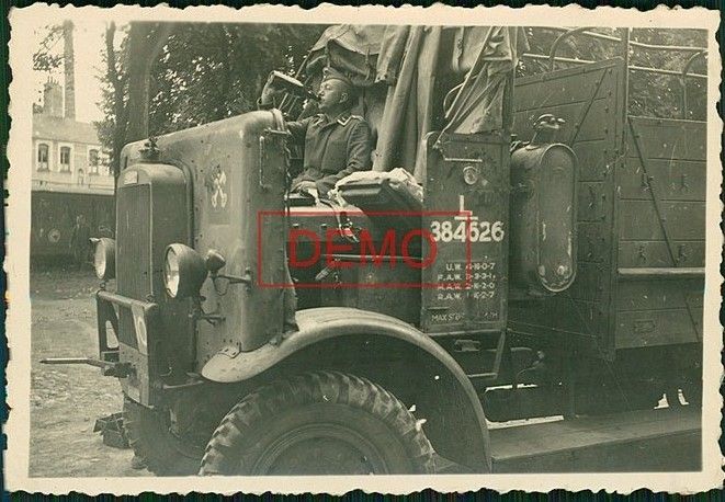
L384626 marked to 506 Field Company RE :-
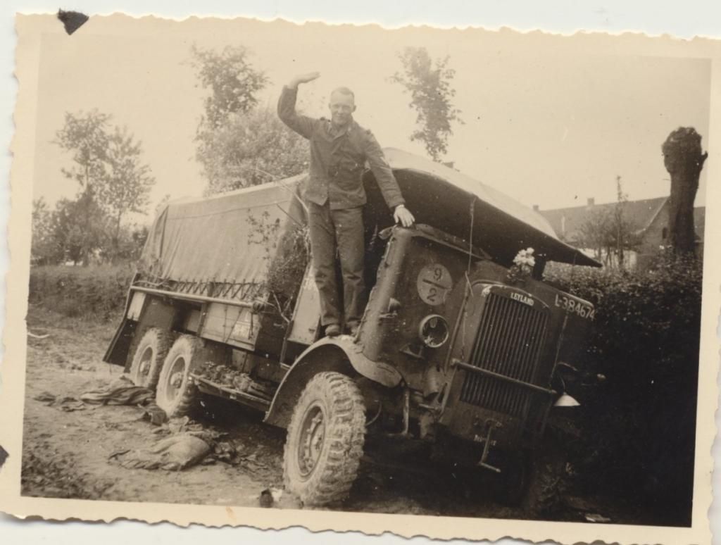
L384674 :-
Nice photos thanks for that.
Pete
-
The next job was to put some strength back into the wing. To do this I had to fabricate the inner wing sections as these had almost completely rotted away. The challenge here was to re-produce the shape of the wired edge on the inner wing. I don’t have a wheeling/crimping machine so I had to hand fabricate the wired edges. I decided I’d make the inner wing section in three parts and weld them together to make the finished piece. I've had some success in the past reproducing wired edges using the following method.
First I mark out the shape of the panel using a cardboard template with the folds and tabs added

To mark out the tab for the rolled wired edge you need to add on enough to enable the edge to roll over the wire and just touch the inside of the panel, bit of ‘O’ level maths needed here to calculate the circumference of the wire being used then add a bit for the thickness of sheet, (this is a test piece that I made first).

Cut out the panel and bend the wire to shape and cut slightly longer than needed. Clamp the wire on the INSIDE (note to self, check twice weld once :blush:) of the panel along the inside edge of your tab.

Turn the welder right down and make small tacks on the inside edge of the wire at 1 to 2cm centers.

Turn over the sheet and first dress down the tab to 90’ this and the next operation are best done in a vice with bending bars or on a small anvil

Now dress round the wire.

Not like the factory job but ok from the viewing side at least.
So here's the inner wing panel completed

-
I know Bernard's condition had been deteriorating for some time but I was still very sad to hear the news of his passing thank you David for the short appraisal of the funeral.
I first met Bernard in 1972 and I can still remember the encouragement and enthusiasm he imparted to a teenager eager to own his first MV.
Bernard's legacy is in the vehicles he saved and restored over a period in excess of 40 years and in the memories that his friends in the military vehicle world have of him. One of the very early members of the MVCG and a pioneer in the restoration of MV's.
He will be missed, my thoughts are with Marion, Henry and Lucy at this difficult time.
Pete
-
The first step was to mark out the areas that had to be removed using blacksmiths chalk. I was careful to only cut out one area at a time any more than this and the integrity of the wing would have been compromised as there was very little strength left in the structure as a whole.
Thin cardboard was then held under the cut out section then from the top side using a thin felt pen the hole was traced onto the cardboard the resulting shape was then cut out and transferred onto the replacement steel. I do nearly all my cutting using ultra- thin slitting discs in the grinder as I find it gives a very clean flat edge. The new sections were then welded in using 0.6mm mig wire and Argoshield cover gas.
These pictures show the replacement patches on the upper surface of the wing.


-
It came as a bit of a surprise to see that I hadn't posted any progress on the Leyland for nearly 2 years. Truth be told other projects have been in the workshop taking up both space and time.
Now things have quietened down and I've got some time to spend on the Leyland. This is a job I've been putting off but it’s high time to drag out the remains of the front wings bite the bullet, get a new roll of mig wire and get stuck in. Both front wings were more fresh air than steel and a lot of the internal skirting on both wings was missing. Fortunately I have been lent a good pair of Retriever wings to copy, I really don’t think I’d have been able to save mine otherwise.
I made a start with the left hand wing, these pictures show what I started with.


-
Not easy Martin I'm afraid always a messy job, taking the skid plate off makes it slightly easier to clean up afterwards. I have a flat sided funnel with a angled spout I picked up years ago but it still runs down your arm particularly when you drop the drain plug:-(
Pete
-
First class job Jeremy I like the attention to detail. One question, what sort of primmer are you using for the wood ?
regards
Pete
-
Thanks for the advice guys and the benefit of your experience. I'll work on the system and tighten up my nuts!!
If you've not overhauled the starter Bill since I fitted it nearly 20 years ago (that's a scary thought) it would probably benefit from an overhaul.
regards
Pete
-
Was the starter dog nose bush changed in the bell housing when a new motor was fitted ?.
If this bush is worn, and they often are, the dog will be pulled tightly into mesh with the starter ring on compression stroke and this will try to stall the starter motor.
Pete
-
I once had a problem with a french made distributor (Ducellier?) on a 270, the base plate was crimped on to the shaft and this had worn so that there was slop, when cold the balance weights would advance and retard as they should, after warming 10+ miles or the shaft would expand and the plate would stick in the fully advanced position. Truck would pull like a train until the throttle was closed than it would miss and die and not restart until everything cooled down. The problem took a long time to locate. Like you I had changed everything on the ignition circuit several times, I finally found the problem when I striped the distributor right down, two tacks with the Mig and the problem was solved.
Pete
-
It's been a frustrating two days, and I'm still none the wiser as to why it all happened? That's what is most annoying.
Given that you have checked and rechecked everything else and you are experiencing loss of power with increased exhaust noise it's possible that you have an exhaust valve problem which could be..... badly worn or incorrect set tappet adjuster, valve sticking in the guide, broken spring, burnt/damaged seat and valve, .
I had the last problem on a Land Rover engine that gave an intermittent loss of power and popping at the exhaust which steadily got worse as the valve/seat burnt at that stage a compression test showed it up. You could also try connecting a vacuum gauge to you PCV port on the inlet manifold and see what that tells you. Some excellent diagnostic data on the web that will help with interpreting the readings.
One other thing........what carb have you got fitted? Carter or Solex?
Pete
-
Fuel issues would seem to be the next port of call, but before you start on that can of worms (this may seem to be well left field but there is a specific reason for me asking) before you move away from the ignition system just check the distributor base plate is secure.
Pete
-
When you get the misfire is there a significant note change to the exhaust ?
Pete
-
Just finished reading this thread, very impressed particularly as you appear to be working outside. Looking forward to seeing the body take shape.
regards
Pete
-
Hi Pete, although the dozer had olive drab under all the red paint it did not have military type data plates. The only plate it had looks more civilian to me but the numbers on there date it as 1941.
Jim.
Interesting, I see the TD18 is listed as a 155mm towing tractor is that on the Christmas list Jim ?:cool2:
Pete
-
is it started by donkey engine or just by hand/motor?
Cheers
Steve
Hi nSteve, it is a 6 cylinder motor which starts on petrol and then is swiched to diesel.
I will try to explain, in the cylinder head there are 3 valves per cylinder, inlet and exhaust as normal for a four stroke motor. The third valve when open leads to a small chamber with a spark plug in it.
So when you want to start the motor you turn on the tap in a 1.5 gallon petrol tank,
pull down a lever on the dash board, this opens the third valve in all the cylinders, it also opens a flap in the inlet manifold so the air is drawn through a carburettor, it also turns the mag on.
when the third valve is opened it also reduces the compression ratio to run on petrol
pull out choke, press the starter button, engine starts.
Run engine on petrol for a few minutes until warm, depending how cold the weather is.
Pull the lever back up and the diesel hand throttle up at the same time.
the valve is then shut increasing the compression ratio
the carb is turned off,
the injection pump is now on and the motor switches to diesel.
To shut down the motor you do the same in reverse.
Simples.
Jim.
I'm suitably impressed Jim, where do you keep your third hand?

Pete
-
Very nice indeed what DoD is the TD18?, The Diamond T, Rogers, TD18 combination really looks the business
Pete
-
Markings on the pump arm on one side 1524424 and on the other side EV GM
Pete


Hello all & Help Needed??
in Introductions & Welcomes
Posted
If you do the job your self a rebuild on the gear box should be around £300-£350 mark in parts be wary of cheaper reproduction components the tolerance and quality can be questionable. Check all parts against factory specs and replace if required, don't short cut this as you'll only waste your time and money. Check the transfer case for worn components and seals while everything is on the bench.
Pete