


ruxy
-
Posts
2,824 -
Joined
-
Last visited
-
Days Won
16
Content Type
Profiles
Forums
Gallery
Blogs
Events
Articles
Store
Downloads
Posts posted by ruxy
-
-
The good news is that it is probably worth 4 or 5 times that of a Sankey narrowtrack in similar condition.
-
Your Sankey trailer - is a BROCKHOUSE trailer , with the standard NATO draught eye messed about it seems ..
-
Your fingers would soon be itching with "vibration white finger" .
-
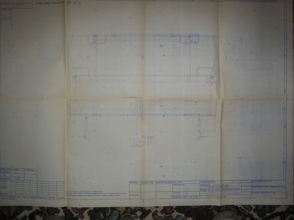
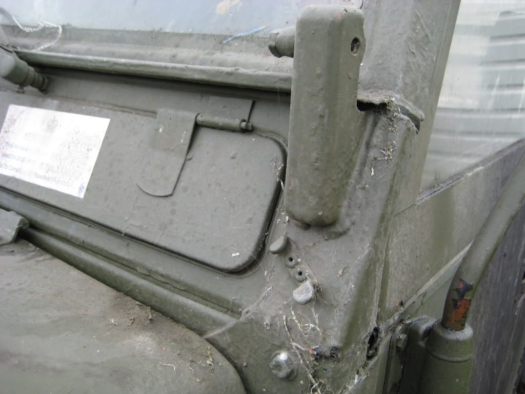
Yes - that front blind could be the type fitted to a civilian bodied S2A or S3 winterized because the type I have seen fitted to a L'wt (two positions set by hooks on grille panel) is tensioned by the two tension springs (see the blueprint) - on to these hooks on the dumb-irons
Of course on a civvy body Rover the front apron would be in the way of the tension springs - so yes it possibly was used on Civvy body (but I have seen furled canvas type on these bodies as well) . Defo. genuine in service kit - but how many had it - it seems a bit late in the day for finding out.
Tony
-
I corresponded with C.J. Williams back in 1992 , they sent me a blueprint of their front blind - so this is defo. REME or RM.
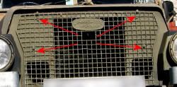
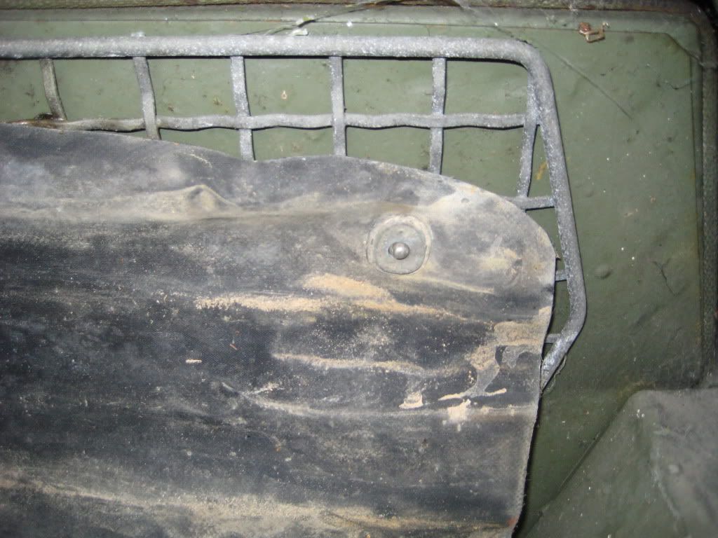
The grill panel does not have the four hooks that a winterized with canvas blind would have and there is no evidence of holes having been drilled for the hooks.
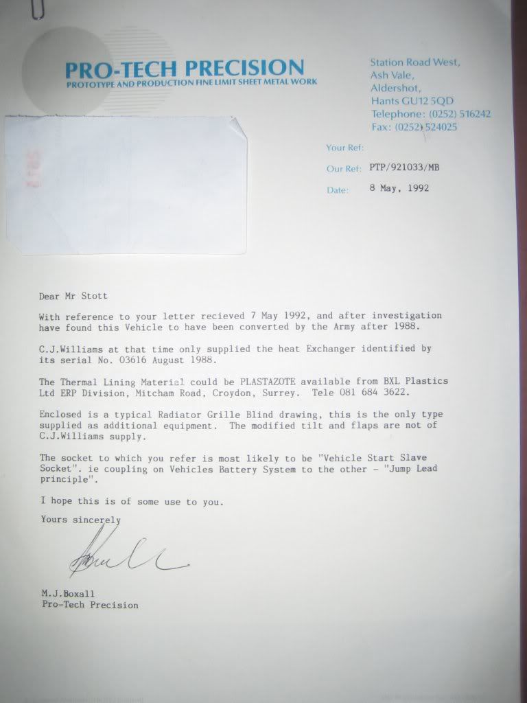
I don't recall having seen a front blind like this before , you can see from the correspondence - converted by MOD not C.J. Williams
-
Royal Marines "Winterized"
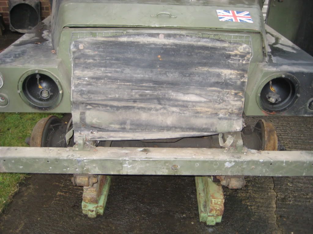
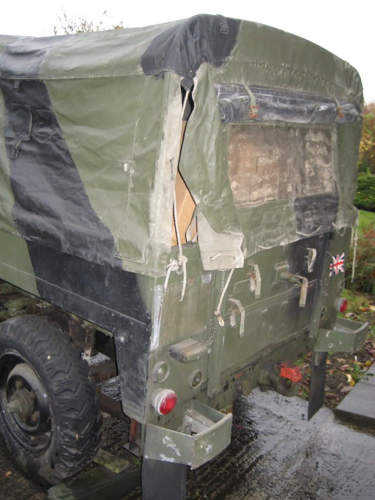
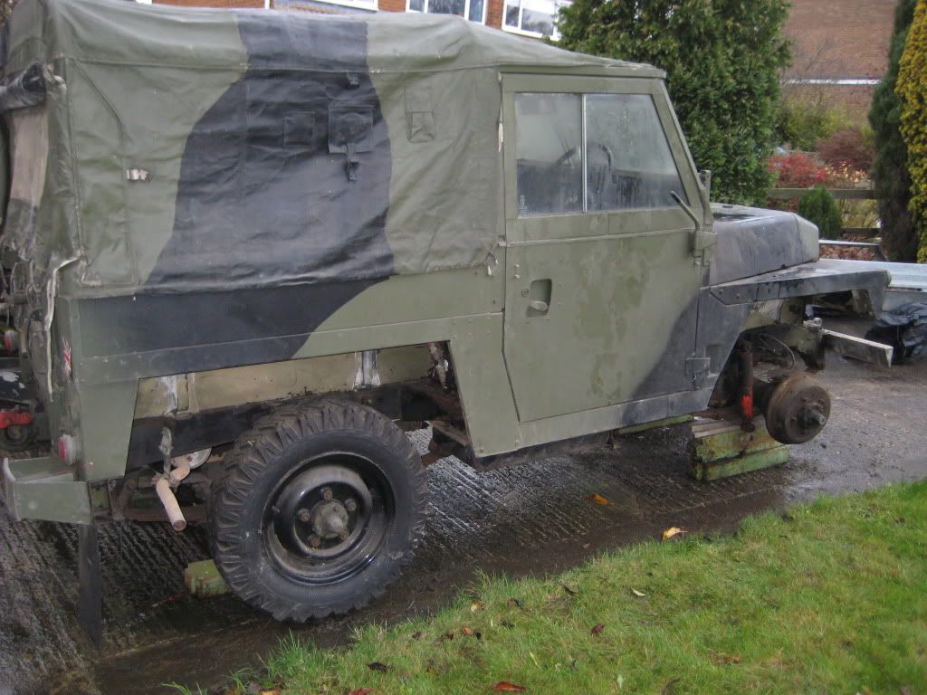
--------------
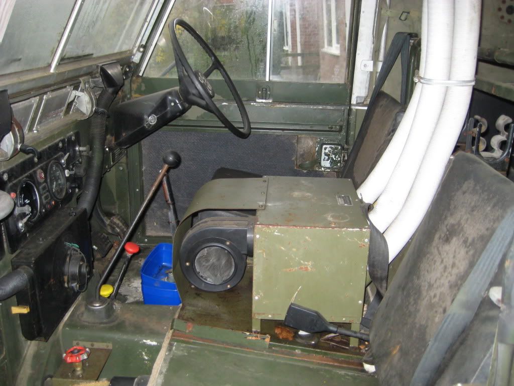
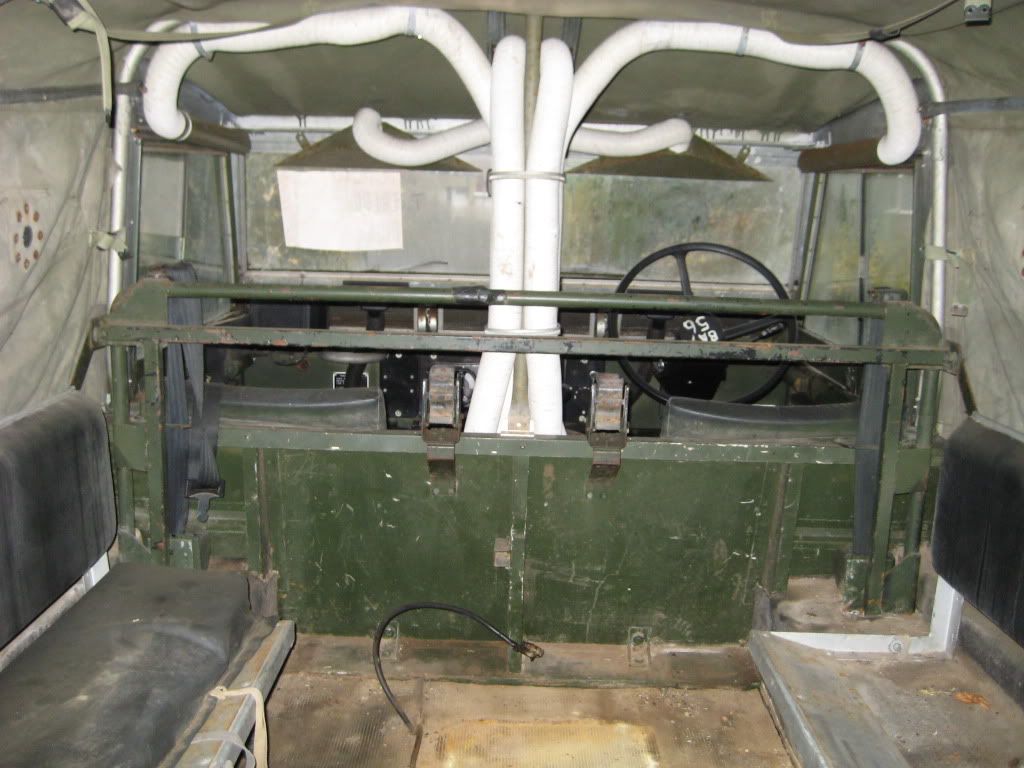
This truck has all the hooks for securing the snow/ice blinds - other than the front panel. The front and rear blinds are a ruberized type fabric (possibly Hyperlon) rather than the normal duck canvas. The front blind is secured with press-studs rather than the tension springs on the canvas type.
No evidence at all of any stitching marks on the tilt of the front screen and door top blinds ever having been fitted.
As part of this project I am preparing another L'wt with a C.J. Williams (Aldershot) winterization kit , slave start and pukka internal thermal lining material. I would be very interested to view any winterized L'wt photographs readers may have - in particular any showing the real FULLTILT.
Regards
Tony
-
I saw the Treadlight fitted lightweight or one to the same spec sold at Blackbush mid 90's, having come from being used at Shoeburyness ranges, where I believe it can get pretty soft underfoot. Can't remember the price though.
Does anyone know it''s original purpose?
============================================
They were created (possibly by Marshall of Cambridge) for the Falklands soon after the 1982 conflict. I forget the quantity - ISTR about six.
-
ISTR - the Ruddington disposals catalogues always had a entry about the Geneva Conventions and use of red cross. When private auction disposal sites were used - this was not the case , possibly just one site in the Uk made a mention.
-

The Sykes-Pick with turret is good - I have one - quality only comes at a price.
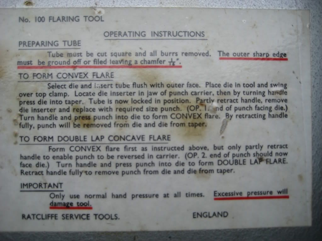
The one I prefer is the Ratcliffe , the 3/16" spare punch is in fact a SP part - you can use it with the dies and it works just the same - so who designed it first ?
The double headed anvil - you place this in the vice first and wind it in to push the dies into the taper to lock & secure (it also positiones the pipe exact at the end of the dies). However as explained earlier - there is still a knack to be learned , not to vice up too tight or slack with the anvil piece.
-
The OP1 (ball end) is designed to be taken up and then crushed slightly to produce the pressure seal , this is often the case with brake slave cylinders , to do OP1 & then OP2 then there is absolutely nothing to compress - muppets often use cheap flaring tools to produce a single flare then tighten up so hard that they almost strip the threads in alloy cylinders. Generally - from what I have seen these cheap flaring tools only produce a cheap simple outwards flare with single material thickness , not the two material flange thickness that OP2 does (a correct OP2 gives some compression to provide a good fluid seal). Also you can find if you look inside such as brass "T" fittings a circular ridge that to provide a correct pressure seal needs a OP2 flare that has the correct inner taper clearance before tightening up - the inner ring form then impinges on the pipe inner taper.
If you have renewed many brake pipes - then you will know that because of this reason many pipes have a OP1 flare at one end and a OP2 flare at the other end.
I may have a few photographs available I can show correct OP1 + OP2 and the cheap tool "universal" flare that is a potential hazard.
regards
-
The Frost tool is a dead ringer of the Sykes Pickavant that I have. The SP is very similar to a Ratcliffe (in fact the dies and punches can be used on either). Even with these better sets there is a knack in getting the 1st OP just right - in particular with cupro nickel.
There is a setting tool anvil to position the tube exactly at the end of the dies but it depends upon how much pressure you have used to close the dies up to grip the pipe , when you get the knack of rotating the closing vice handle (Ratcliffe) or lever (SP) just consistent and correct it all comes correct. You may need to try dry & with a bit of brake fluid on the tooling.
-
The last WW2 era reserve type stock that I know of were the WC54 Ex-Norway ambulances. A friend had one - he obtained it IIRC sometime between 1995 & Y2K.
ISTR there were also some CCKW's released , or were they early 1950's Deuce & Half's ?
There were Land Rovers , AFAIK out of reserve , returned to UK from Germany mid to late 1980's. Stored in RAF hangars and sold by invited tender only in batches of 30 qty.
-
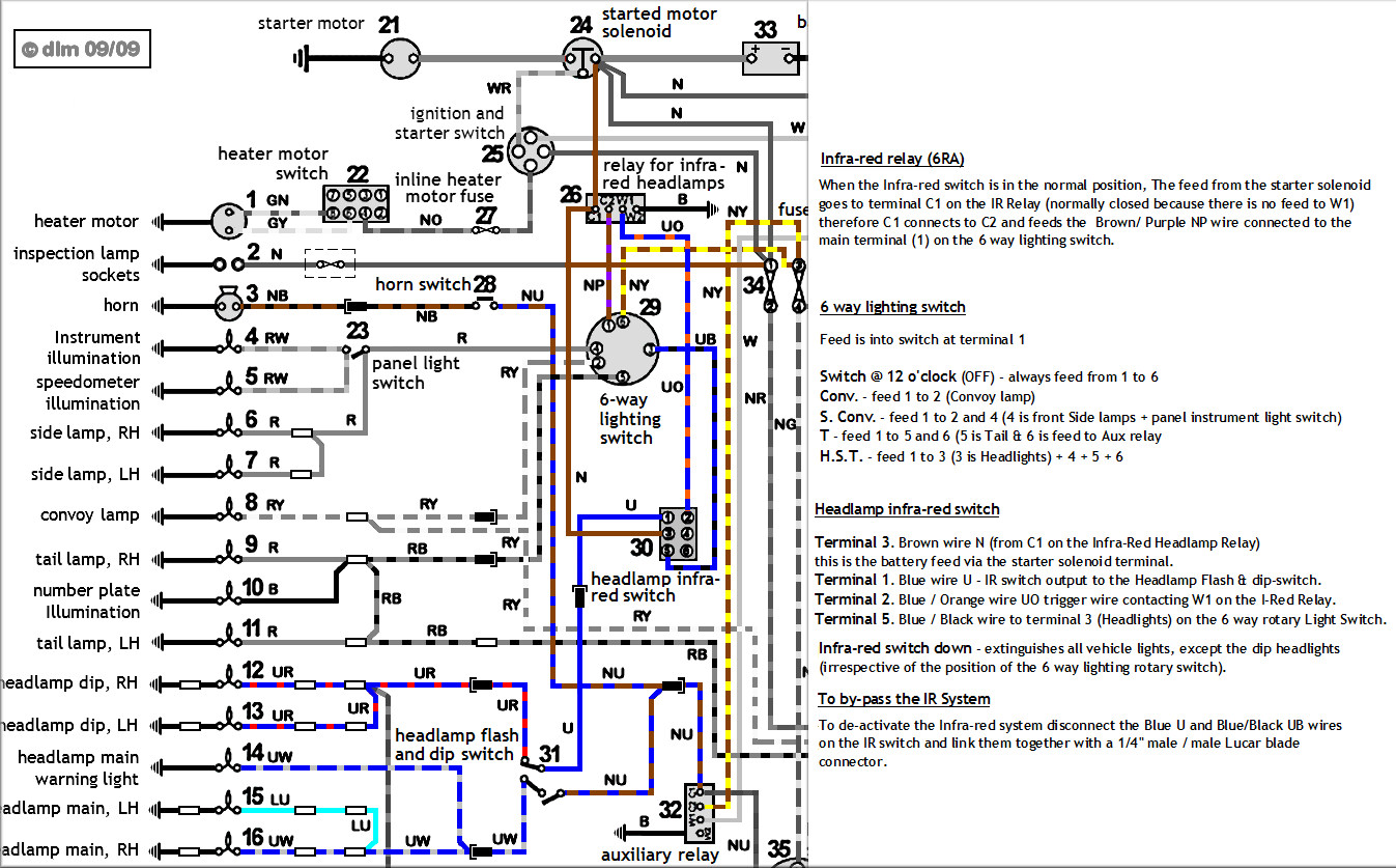
Over 30 years ago I worked out a truth table for continuity check across the numbered terminals of these 6- way switches.
Just follow this with your AVO.
Swith @ 12 o'clock - OFF , always feed from terminal 1 to 6 (fuse in steering column fusebox)
Switch positions :-
Conv. - feed 1 to 2 (Convoy lamp)
S. Conv. - feed 1 to 2 and 4
(4 is front side lamps + panel instruments light switch)
T - feed 1 to 5 and 6 (5 is tail & 6 is feed to Aux. relay)
H.S.T. - feed 1 to 3 (3 is Headlamp) + 4 + 5 + 6
The above should also work good with all / most Military Land Rovers.
IF YOU DO NOT HAVE CONTINUITY ACROSS TERMINALS AS ABOVE - THEN THE SWITCH IS BLOWN !
regards
-
Not to bother then Clive , all history now (well almost for me - and I still havn't needed any of those fuel pipes , just as well I purchased them).
-
Do you have any technical info. just what these modification job tasks were Clive.
regards
-
Not quite as simple as you explain it, this went on for some time, with lots of trials and testing done. The contamination of the paper air filter.....I recollect a modification being introduced, I said at the time, what idiot would design a breathing system feeding crankcase vapours to the suction side of a paper filter, it was bound to clog as it was mixed up with incoming dust.
As for dipstick levels, these were altered when rebuilding the engines, and measure ot the fraction of an inch......this amused me because once an engine is running, oil is splashed and pumped around, so unless the level was grossly too high, it would not be a problem. Another thing, vehicles, especially off road ones, work at all kinds of angles, so another reason why the oil level was a red herring.
=================
The problem being with a Land Rover dip-stick tube , you have to calibrate it at the gland nut & olive assembly at the crankcase and they come loose , not anti-tamper - if the setting is incorrect and there is too much oil content in the sump - it can lead to contamination of the paper element (this is the story Rover maintained to even their private customers and of course that the tube height was correct but that the engine had too much oil on the dip-stick). Rover maintained that insufficient time was being given for oil to return to the sump and the squaddies were too hasty to top up - the result of this was the parade ground procedure.
Unfortunately I am unable to find a Vortex unit just now , somebody else may be able to assist with a photograph of the set up..
-
As a follow up , this is so long ago - was the reason in fact finally found to be :-
The servo brakes vacuum pump (evacuator) that sits where the distributor does on a petrol) . These pumps suck air from the servo and dump it (complete with their lubricating oil) into the crankcase. When fitted with a servo, the pump spends most of its time not pumping, so pushes no air into the crankcase. If the servo is disconnected OR YOU GET LOSS OF VACUUM ON HOSE CONNECTIONS - then the evacuator simply pumps loads of air into the crankcase, pressurising it to an alarming degree.
-
The problem on 2.5 na engines on early military 90" & 110" contracts was due to oil contamination (blow-by) of the paper element air filter.
IIRC there was questions in the H of P.
Land Rover blaming squaddies overfilling the oil level. I was reliably informed there were officer witnessed morning checking of dip-stick levels on flat parade grounds as this was denied.
The pistons were made by AE (Associated Engineering Group part of Turner & Newall) at their Bradford works, piston ring sets were made at the Sunderland Works of Hepworth & Grandage (part of T&N Group - later Federal Mogul / AE Goetze).
The matter was only resolved by a REME Major who designed a "Cyclone oil recovery scavenge canister" that was installed in the engine bay with associated pipework.
I should be able to turn out a photograph of one of these scavenge canisters.
There were free issue of hundreds of new engines to replace wrecked units that self destructed as they could not be stopped dieseling on lubricating oil.
I forget the full story but IIRC the problem was resolved by re-designed piston sets , but it took Land Rover a long long time, there was still Rover denial to their civilian customers who were also affected badly.
-
ISTR (and forget at MOT time) for FOG GUARD to work you need your headlamps on.
You need to sort your headlamps out first.
It would be better if you were able to state the VRN of your Lightweight , fog lamps appeared about HG (1980) and at first there was still a Infra-Red switch with Aux. (FV) relay. IIRC by KA the Infra-Red circuit was deleted.
If post KA then I would suspect the headlamp switch (copy ones are hopeless).
If prior to KA - then I would first suspect failure of the Infra-Red switch (famous for leaving you in the dark with only sidelights - another story).
You may best off to sign up for the ExMLRA Forum.
A gent (Disco 2000) there is doing many Lightweight versions with full trace colours, this is going to be a boon for future fault finding. I have been providing him with info. the drawing you specifically need may be the one I am having difficulty with - there may be a Fog relay as well.
This is where Disco 2000 (Dave) may have a for relay disconected :-
http://www.land-rover-lightweight.co.uk/Images/Electrical/Fog%20Relay%20Wiring.jpg
-------------
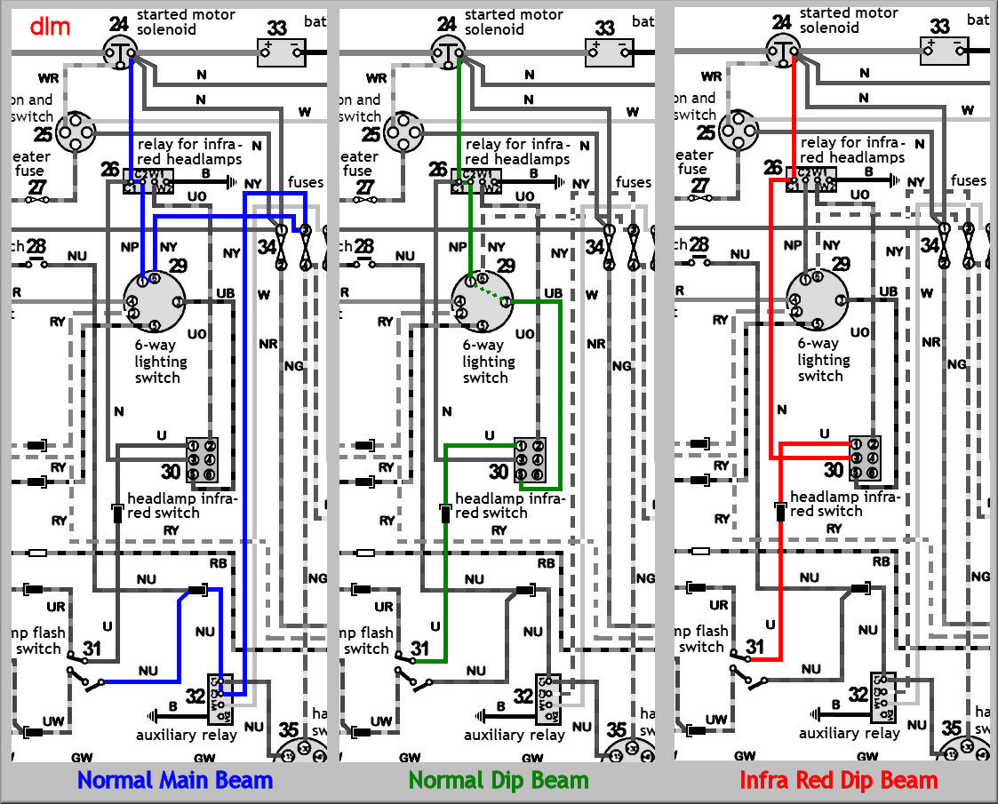
http://www.land-rover-lightweight.co.uk/Images/Electrical/IR-Headlamp%20RelaysA.jpg
http://www.land-rover-lightweight.co.uk/Images/Electrical/Head%20Lamp%20Diagram.jpg
The above two diagrams and notes will explain how you can loose your headlamp lighting.
Something makes me think I have found such a relay laid amongs the wiring behind the dash on a Lightweight, don't know why they did not mount it above the service brake automatic check relay that was introduced.
http://www.land-rover-lightweight.co.uk/LRL%20M.html
==========
Also :-
http://www.winwaed.com/landy/mil/military.shtml
A few not so handy diagrams (late) with fog guard , non colour but key can be viewed on another page.
-
Not much use for MT but a bit of info. Read a couple of books recently about WW2 night fighters , to help stop the Hurricane exhaust stubs glowing red in the dark they were coated with red lead paint after every sortie. I suppose this would be the real red lead paint now almost impossible to obtain.
-
The final act of a restoration (before the breakdown repairs start) - is to paint your diff. pan white http://www.hmvf.co.uk/forumvb/images/icons/icon10.gif
WTF
-
http://forum.emlra.org/viewtopic.php?t=5355&highlight=inter+vehicle
QUOTE.
SAS dinkie
Cpt Mainwairing
Cpt Mainwairing
Joined: 01 May 2005
Posts: 581
Location: West Sussex
PostPosted: Thu Apr 23, 2009 10:43 am Post subject: Reply with quote
Ah, but the one for a ferret is the wrong one for a wolf....... the ferret one is te early one with smooth cap, the wolf one is the later one with ribbed cap, the caps are not interchangeable.......
_________________
I have a bog standard 90" 57 KG 59
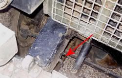
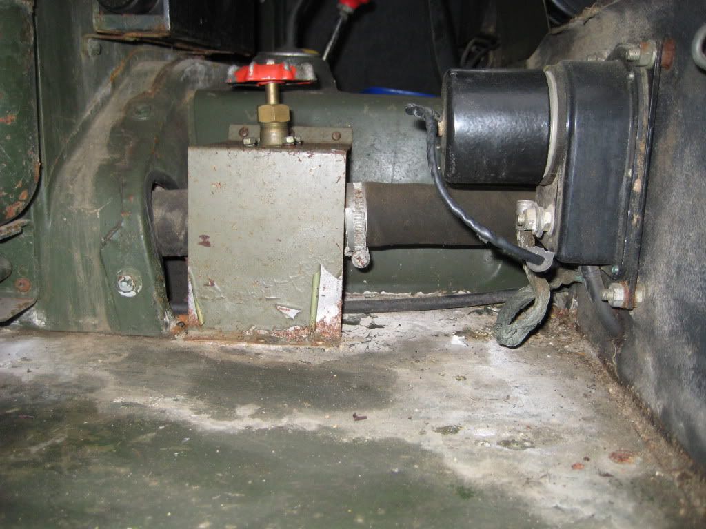
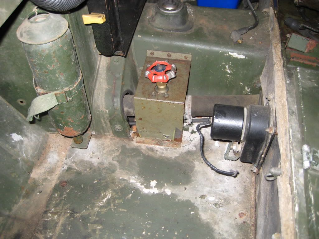
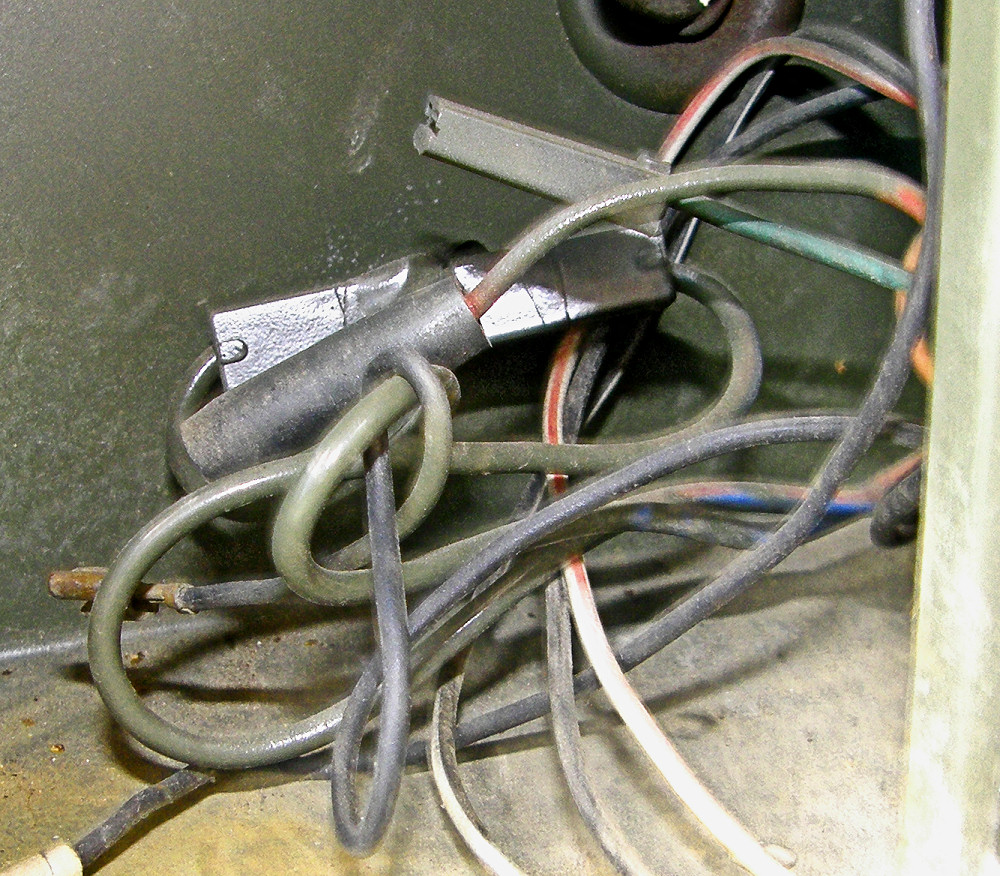
On the basis of the above posted by SAS Dinkie who has greater knowledge of coilers than I have - I obtained a socket with plastic cap to be more correct (in garage & still to fit) - just in case I need to do a slave start for real. However - he is talking Wolf and my 90" is not even a Defender , so it seems I could use a metal cap type.
I don't know when the change point was but probably old stock lasted a few years.
I have examined a few dozen winterized Lightweights but only seen the metal cap type but there is plenty more to eyeball yet !
-
OK 'ish price - you may find one cheaper if you watch and wait.
Note - this is correct type for Lightweight (black alloy cap) , with a black plastic cap - then this is more Defender era.
-
The Lightweight springs in fact have greater free curvature , this is why the 7 leaf front (FFR & later GS) have 22mm packers between the bump stop and underside of chassis. The ride height is upwards a bit compared to a civvy 88".
If used mainly on surfaced roads a better choice is standard 109" rears , standard 88" petrol fronts (or diesel if you want firm).
Original Lightweight axle hubs were oil lubricated from the axle.
Later Lightweight axles are more or less civilian spec. (after the 1980 88" upgrades "rationalized") same spec. as 109" on front with oil slingers, locking ring at end of stub-shaft with snap ring , internal oil seals in end of axle tube (so no longer oil feed to hubs) - so not at all like the earlier S3 axles. The hub caps can be metal or plastic and are a slightly different profile to original series.
Arguably the earlier reinforced axle casings were stronger (1 ton rated) but IIRC the later casings are 750 kg. rated so still well over the top.
WW2 snaps
in Research Centre
Posted · Edited by ruxy