


simon king
-
Posts
642 -
Joined
-
Last visited
-
Days Won
3
Content Type
Profiles
Forums
Gallery
Blogs
Events
Articles
Store
Downloads
Posts posted by simon king
-
-
i am currently recreating the radio bench for the MWR. It is the sort with the sliding pull-out extension under the top boards and a draw below that. All the pictures I can find on the web seem to show that this type of bench had a sloping draw front presumably to give more leg room. I intend to reproduce that type of draw
I inherited a newly made angle iron bench frame and slide out frame with the vehicle, as the originals were well pitted/terminally corroded, together with some rotted woodwork to act as patterns.
I have two different bench tops - each made of 3 1" planks. Both of these tops have witness marks showing that the bench tops came pre-installed with 5 metal strips each 131/4" x 13/4" in a precise pattern as can be seen in the different examples on the web (eg MLU Wireless Forum's 15cwt wireless truck furniture thread and pictures of the Garrison's MWR). Presumably these strips which seem to come undrilled were to take account of the different equipment which could be likely fitted on the bench.
I have some questions though
- do you think it would have been necessary to use the Table Mounting Strips which came as a set with the Mountings, Carriers No 1 if the bench came pre - installed with those strips
- I have been trying to match the holes in the shock absorber feet (both attached to the carrier) to holes in the tops. I cannot seem to match holes to the specified four 1/4" bolts per side - so would a bolt in just one of the two holes in each shock absorber suffice - two bolts per side can be matched
- was the 19 set wireless and PSU somehow earthed via the No 23 carrier, and the carrier then earthed to the bench (possibly through the Mountings, Carriers) which in turn would have been earthed to the vehicle? Or was the wireless and PSU earthed directly to the bench - which seems at odds with the portability aspect of the installation.
Any advice gratefully received
Thanks
- do you think it would have been necessary to use the Table Mounting Strips which came as a set with the Mountings, Carriers No 1 if the bench came pre - installed with those strips
-
Yes I have one fitted to my Bedford MW, I used the lower body from a spare champ fuel pump I had as it uses the same hole pattern just swapped the actuating arms over, fitted a new rebuild kit diaphragm, valves etc and away to go :-D I think I might have posted some pics on my restoration blog, hope I've been of help
RR.
Thanks for that. Very helpful. That will be the next project after finishing the woodwork for the radio bench......
-
Rather than draining the battery to pump fuel through the lines from the tank, I want to fit a fuel pump with a hand primer to my Bedford MWR.
Has anyone done this and how did you go about it? I seem to recall reading somewhere that a Champ fuel pump or parts thereof could be used but I cannot find the thread now.
Any advice gratefully received
-
What a pitty with the Vickers medium.
But one could argue if it had been restored, if it wouldn't have been more of replica incorporating original bit, than an original, based on that picture.
No different from most airworthy Spitfires then.....
-
Post war tetst on the Foker Angelus towed by U Boats?
If I remember correctly, The Airborne Forces Experimental Establishment used the original Rotabuggy Jeep for that, still with its ASI and altimeter fitted, but with the tail and rotor removed, towing a platform trailer made from the chassis and base of a 2-wheeled airfield control caravan
-
.Is that Raoul Hafner and a prototype/test rig of the P5 Rotachute ?
-
Hi Simon, is there any way you can get a few measurements for me please.
- Distance the plate is from the top rail
- length of plate
- length of the cut out that the handbrake lever sits in
Best regards
Dave
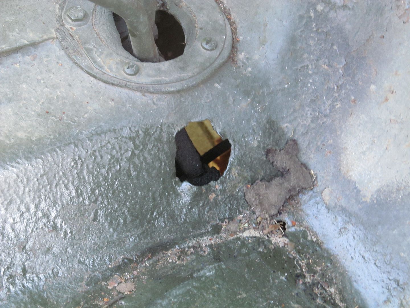
Just sent you a pm with dimensions. Here are some pictures of the rusted original section I kept to remind myself of the state it was in


- Distance the plate is from the top rail
-
Dont know if this helps - its a view from the top

-
Again a low flying military vehicle first the LR now the Jeep
And another

-
Congratulations to all concerned with the relaunch of CMV. Let's hope that the improvement is sustained and built upon. I note also that they have finally dropped the MMI titling from the front cover as well.
-
The Chilwell List suggests that dataplate is very late war - manufactured by Taskers of Andover. Interesting that it says "chassis" not trailer - possibly an lightweight water bowser?
-
Hi Simon I was thinking of getting on with the tool box as its a nice indoor job, if you could post / PM or email it to me that would be great.
Also drawing for the canvas please as that's another small job I can tick off the list.
Regards Ian
Ian,
pm me with your e-mail address
-
Ian
i have the dimensions for the woodwork and ironwork for the front toolbox if required-scaled from photos and known dimensions. The ironwork for the box will require some cutting and welding of proprietary hinges and hasps. You pointed me in the right direction with regard to the padlock turnbuckle. It is the same Land Rover part as used on the bowser's box.
Replacement chain can be obtained from B&Q. If you are missing any of the tie down hooks, my local smithy made me more than required for my own restoration.
I also have a drawing for the canvas.
Tony
The use of those three brackets remains as elusive as ever. The same basic chassis was used for GS mortar and DF trailers so I wonder if it was for something on the DF trailer. I even wondered if they were for wooden rollers to wheel them round the factory.
sk
-
Ian
I'd be inclined to practice on plain paper first to check sizes etc.
Little Cars offer a good quality white decal paper and the Microsoft Decal film you need. I've used others but keep coming back to this stuff because the ink seems to dry much quicker:
http://www.modellingtools.co.uk/white-decal-paper-for-inkjet-10240-p.asp
I spray the decal film with no thinning - seems to work OK
http://www.modellingtools.co.uk/microscale-liquid-decal-film-11803-p.asp
HTH
sk
-
If all else fails you could make your own relatively easily
Do the text in the appropriate font as a word document or image. It could then be simply printed in black onto white decal sheet with an inkjet printer. The decal would then need to be trimmed and sealed with a proprietary decal film such as that available from Microscale. It can then be applied like any other decal.
I have used this technique to good effect to make decals for 19 Set variometers and control boxes.
-
There was a BRIXMIS modified 4x4 Opel at the National Army Musuem at Chelsea for years. Now it has dissapeared, I'd love THAT as a toy! :cool2:
Wonder if it is the one now exhibited in the Cold War hall at the RAF Museum at Cosford
-
It's great to see Jeeps in British markings! But, being just a bit pedantic about British military terminology, if I may; COs - commanding officers - commanded battalion-sized units. Squadrons, batteries, companies and the like (sub-units) were commanded by OCs - officers commanding, while troops, platoons and sections were commanded by, troop commanders, platoon commanders and section commanders respectively. Not that the military always get it right - certainly nowadays you will often hear soldiers referring to, for example, their "troop OC"!
10 68
Markings are for the Jeep of Lt Col. P Serocold, Commanding Officer of 2nd Derbyshire Yeomanry. Markings were drawn up with the help of the 2DY OCA who showed picture of finished Jeep to PS. He initially commented that he didn't know that anybody had taken a colour photo of his jeep during the war - which was quite pleasing
-
CO's Jeep, HQ Squadron, 2nd Derbyshire Yeomanry

Markings painted on rear bumperettes

-
Often seen modification to allow the 4wd and high/low ratio levers pivot pin to be eased out with a minimum of effort to replace seals / remove body/replace lever springs etc etc
-
Anybody got an idea about the current turnround time for vehicle enquiries to the RLC Museum? My enquiry, using the form available online was sent to them in the middle of August
-
The two magazines which are now one, came after the demise of Wheels & Tracks, and neither of them have ever matched W&T. Under Bart Vanderveen, we had well researched articles in great detail when a particular vehicle was profiled. No text written over photographs so it is impossible to read like CMV does either.
In addition, with W&T you felt part of a community of MV enthusiasts and restorers - something neither MMI or CMV have ever really engendered. I think of the first 5 or 6 pages of Bart's editorial in each W&T which contained details and snippets of discoveries, restoration updates and other news-worthy items which were always just as interesting as the feature items.
That of course depended on Barts reputation and circle of contacts which were propably unrivalled at that time. To quote an example close to home, I would have probably sent before and after shots of my 10cwt trailer to Bart because I know he would have been interested. Whether they appeared in W&T was of absolutely no consequence to me. I would have sent them because I wanted BV to see them. It didn't even enter my head to send copies to the editors of MMI or CMV.
It is interesting to ponder how W&T would have evolved had not BV died - perhaps it would have just stayed the same - as after all that is the format that everybody always seems to hanker after today.
As I think I said in a previous thread on the subject. MMIs and CMVs problem was, and always will be, that they are not W&Twhich has since it's demise acquired legendary (in the truest sense of the word) status. The dichotomy is that W&T was always indivisible with one man, and the magazine died with that man so any substitute is unlikely to be compared favourably.
CMV/MMI have had long enough to plough their own furrow and find the "W&T sweet spot". That neither did/has needs careful reflection and more that a few focus groups to find a new direction that ultimately allows it to be as revered as W&T.
Sorry - boring fart bit over
PS what restorations have the Tank Museum done - other than keeping the running fleet running. The Covenanter, AVRE Tetrarch, Vickers Medium and Matilda I were done by external contractors/bodies. I thought they had an A30 Challenger for restoration - whatever happened to that?
-
What would I do without my informal support network! Thanks again
It's never easy though is it!. The strainers are of a different type which seem to somehow screw partway into the hole and have a single securing screw with an eye made from the spring itself coming out at the side.
Like this

Furthermore to add insult to injury the diameter of the hole in those three retaining cups is larger than the diameter of the spring end so they wouldnt retain the spring anyway.....
-
Hey guys,
I'm also looking at a Sherman Firefly chassis and turret with a group of friends willing to split the bill eight ways. The Firefly needs some serious work however, mainly a demilled 17pdr breech with an un-cut barrel with the muzzle brake and also a modifed M34A1 mantlet. I don't know where I'd find both of those honestly because they're kind of rare nowadays, at least here in the US that is.
Fireflies must be pretty rare in the USA full stop (period). I think a complete turret was shipped to the USA and one to Canada during the war and that was the sum total of transfers across the pond. How did your Firefly arrive in the States?
-
I picked up a couple of NOS Remote Control Junction boxes at Malvern yesterday for the drop leads and spares recovery. These boxes have one male and one female drop lead. Is it possible to get into the rubber cone plugs to convert a male plug into a female plug using parts recovered from the old tropicalised plugs?
If not, i'll just attach a male plug into the control box until I find another drop lead with a female plug
Edit
one futher thing that has got me stumped - how do you get those spring wire protectors to fit into the control box? I obviously took them off - but can I hell as like get them back on- wierd as I thought I had taken care to note how they came off............
thanks


Bedford MWR - radio bench
in British Radio Equipment
Posted · Edited by simon king
Hi Chris,
it is the No 23 wooden board fitted in the MWR with the croc clip at right rear and an insulator on the right hand metalwork. The mounts are the correct carrier, mounting, no 1 used for the no 23 board. Two correct bridge type shock absorbers are fitted to each carrier, mounting, no 1.
i can easily make the strips that came in the kit with the carrier mounting no 1 , mounting bolts and the shock absorbers themselves, but I was just wondering if these were required if the radio bench already has those 5 strips factory fitted in the places where the shock absorbers would rest. My presumption was that the strips were intended just to prevent the shock absorber/bolts from digging too far into the wood surface through over-tightening.
Where is the bond strap from the front bottom RH corner of the 19 set attached to the metalwork of the carrier no23. It must somehow be in electrical contact with the croc clip.
thanks