


simon king
-
Posts
642 -
Joined
-
Last visited
-
Days Won
3
Content Type
Profiles
Forums
Gallery
Blogs
Events
Articles
Store
Downloads
Posts posted by simon king
-
-
two nice items for my MWR project,
generator and roof window....
The MWR carries the 300w Chore Horse generator in the locker that acts as the drivers footstep. That type of generator is more commonly seen in Airborne signals jeeps I think.
i believe the original 300w generators were of Canadian manufacture although my MWR came with the later BSA clone.
-
Interesting thread on the FlyPast forum, showing that SCC1a was still available from RAF Stores as late as 1958 for the refinishing of tin helmets
-
That's an interesting Marmon Herrington Mk IV with the turret removed and a Vickers 2.75" mountain howitzer added.
-
On my Pc I have the usual HMVF corporate appearance, but when I go to HMVF on my iPad, i just get a generic vForum presentation with none of the HMVF add-ons.
This has only started in the last couple of days - anybody else having this issue?
-
Yes Simon, you are correct.
Elements of 9th AD who used Covenanters were transferred to 79th AD when 9th AD was disbanded (27th Armoured Brigade for example) and so presumably they still had some of their Covenanters on hand to use for training. Speculation unless somebody can come up with more definite proof.
Thanks Tony - interesting. A Covenanter was probably the last gun tank I expected to see carrying such a sign. If from the same original source, could this hull have been a bridgelayer by any chance? I suppose they just collected any Covenanters from storage for use as range targets though.
sorry for the diversion from the main event!
-
Well done to everybody involved in this recovery. Looks to be a challenging restoration but it seems that the parts required are out there. Am I seeing things or is that a 79AD Bulls Head on the previous Covenanter recovery - and why...
-
Hi All,
Does anyone know what/who the initials 'C.I.M' on top line on the body plate from our 1940 Austin K30 GS truck refers to?
Cheers
Mel
CIM = Chief Inspector of Mechanisation
-
Amazing photo coverage of this new museum in France.
-
Dick,Kerr Petrol Electric tractor with E class well type bogie wagons. Note the rerailing bar resting on the axle boxes of the tractor. Essential equipment on the 60cm lines.
-
Deposit has been put down on a rear MWR canvas to be made so hopefully in a few months that can go on.
Also, I have an extremely helpful friend making me a spare wheel carrier when he has the time

My stamped number on the chassis is prefixed MWR although now that I have trawled through the Chilwell list of B vehicle numbers, the contact is simply listed as Truck 15cwt 4 x 2 utility rather than specifying body types. The post war key card lists it as a 200 gallon tanker, notwithstanding the stamped chassis number, though. So perhaps it was rebuilt as a tanker from an MWR - who knows.
No clues on the card to its original Z number, simply that it was a rebuild from a YT number, the key card for which gives no further details.
Where are you getting your canvas from?
Following a chat at the weekend, I think I know who that extremely helpful friend is, but I've got to draw mine up first of all before he can start....ha ha
-
I am more or less there with this part of my MWR restoration, although i am still on the hunt for a B set tuning wheel and a B set aerial insulator. The latest addition, picked up at Malvern is a reproduction waterproof cover, made by Frank Brown.


-
Peace of mind for not much more than the cost of a packet of cigarettes seems a no brainer
-
Anyone got any dimensioned drawings of British 6 Pdr, Mk IV?
Pete
There is a thread on this subject on the Allied Forum on Missing Links with detailed information supplied by Adrian Barrell
-
Thanks - can't imagine why I couldn't find those particular ones when I searched. I have now ordered some of them so will see how they turn out.
-
Another once common item which seems hard or impossible to find. The MWR has lockers which are closed and locked by padlock hasps and staples made from steel rod, rather than pressed steel. The staples especially are made from u-shaped rod attached to a fixing plate, rather than from stamped flat plate which now seems common.
I assumed it would be possible to just go to a d-i-y shed or on-line site to find some suitable replacement items but that seems a non-starter. I've also tried old style hardware shops in the hope that they might have some old stock somewhere but again no luck. Nothing seems either to be the right size or of the right construction.
I'm beginning to wonder whether it is now time to start searching in Architectural salvage yards, but before I do that, does anyone know a source for these old style hasps and staples.
Thanks
-
Interesting that your MWR was converted into an MWR from an MWD by REME in 1951. My own MWR has a WV3 rebuild plate which gives it an MWRxxxxx chassis number yet specifies an MWC contract so I wonder if a batch were rebuilt/converted into MWRs to meet a specific need for MWRs in the post war period as newer 15 cwt GS trucks came into service. I haven't stripped the stamped chassis number to reveal the prefix yet.
Some of the MWR furniture seems original but substantially rebuilt. I wonder if some of the other furniture dates from the REME rebuild as it uses the same wood as the repairs on the original bits.
-
Thanks for that -although I think that's actually a picture which I happened to spot by chance one afternoon on Flog it. Funny how stuff circulates on the web and comes back to you.
MWR furniture detail pictures seem few and far between. The two firms that did the coach building for the MWRs seem to have different ways of making the cupboard doors. One uses vertical planks joined by battens on the back, whilst the other uses horizontal rails top and bottom with vertical infills, all joined by dowels
-
A - Thanks for that. I think some cabinet making looms
N - something on its way later today
-
Hi
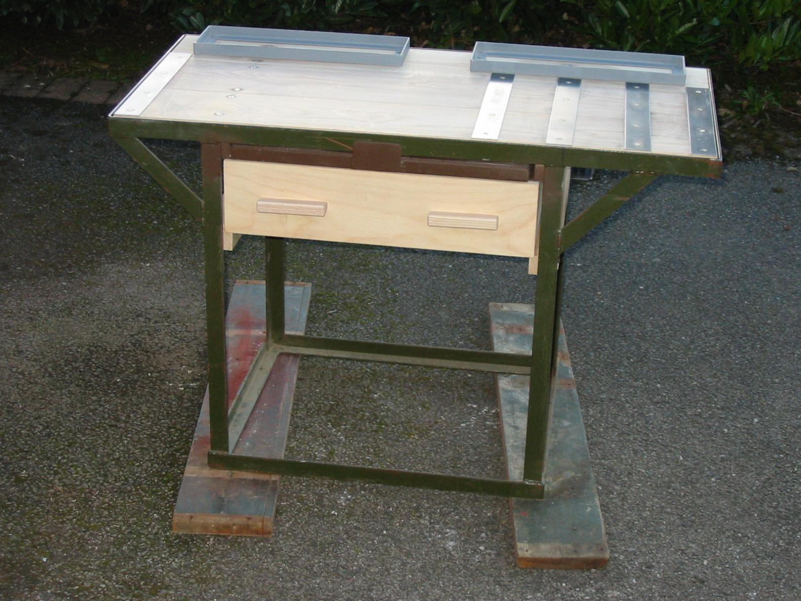
That table looks really nice, is it an original?
I was recently given a WS Set no 19, and thought it would be fun to make that table type for it.
But I dont have any pictures of how the draw is made and hung on the table, and the same goes for the pull out tray, would it be possible for you to take some pictures of it?
Cheers
The new frame, tray frame and metalwork came with the truck - along with a severely pitted original, fragmentary tray frames and rotted woodwork which was good enough to use as patterns.
Leave it with me - I'll measure up tomorrow and take some photos
There are metal slider plates (which I will also measure) upon which the pull out tray runs. The tray has stops at the back to prevent it coming out too far. The plates are L-shaped to stop the draw from going too far back. The draw is as wide as the legs and long enough to fit completely under the bench before hitting to stops. Depths can be estimated once you have the sliding tray secured. There are wooden blocks screwed to the side of the draw, which is just four sides plus ply bottom, to stop the draw from coming completely out.
PM me with your e-mail address and I will scan my woodwork drawings - although double check to dimensions of your own radio bench. I used the Mk 1 eyeball for the tray - no drawings.
Be careful 19 Set collecting becomes addictive
-
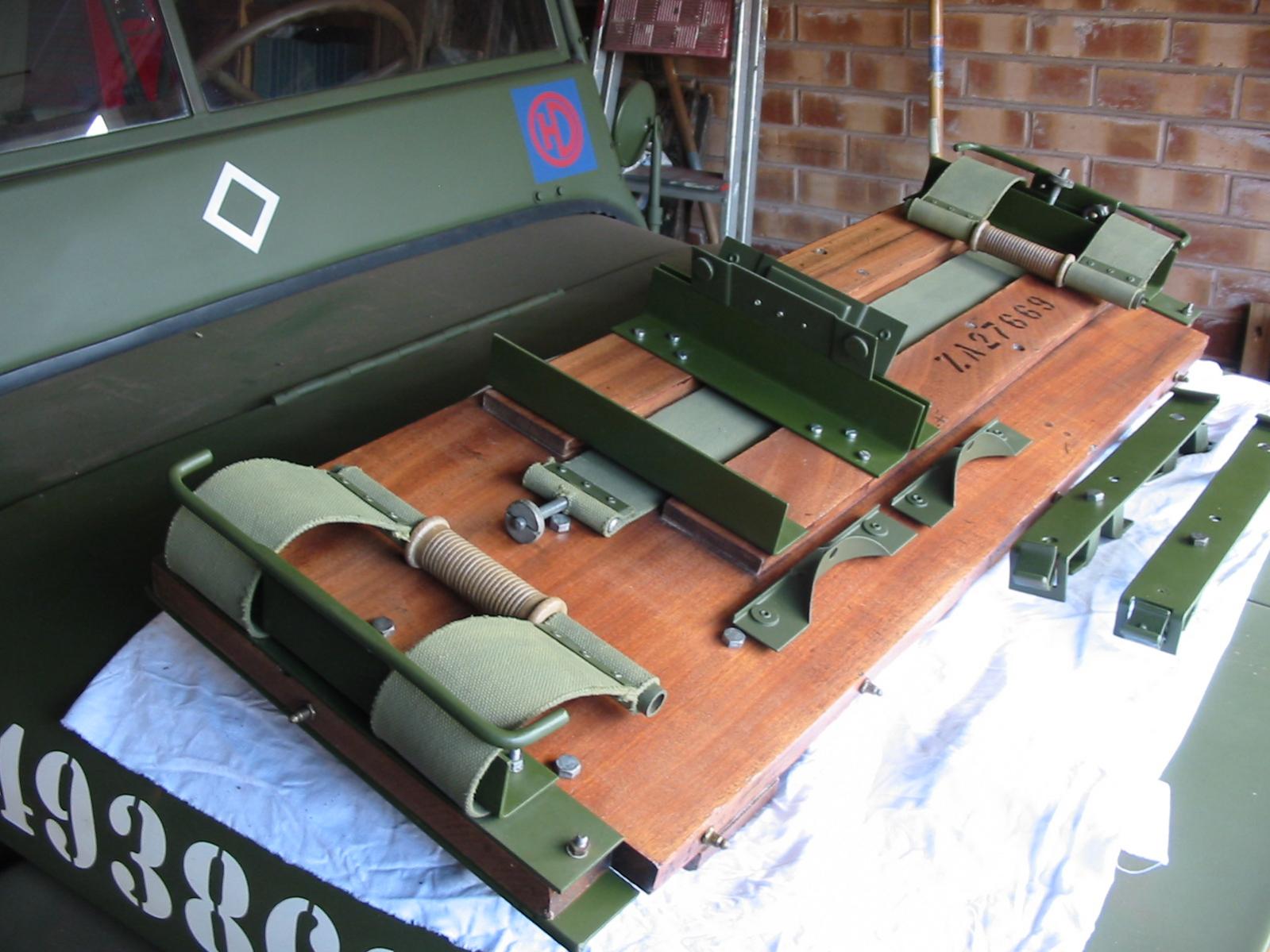
The glacial restoration of my MWR continues and as the refurb of the 19 set installation is approaching the end, my thoughts are turning to the furniture in the back of the truck.
I have finished, bar painting, the radio bench and am now stripping and refinishing the various lockers and thinking about the wiring to and from the control board. Inevitably the more you know, the less you know.
The 19 set installation has two pairs of batteries, one set of which is clamped below the radio bench. I am unsure about the other pair. Are they stored, charged, in the lockers at the rear of the truck. Is that why the lockers have a wooden lip - to stop the batteries from sliding against the locker door?
The tall locker I have has a full length lower door, with no lip but does not seem to be of recent manufacture so I wonder if things were changed at some time in the vehicles life - perhaps during a REME rebuild in the late 40s/50s. I now have the dilemma - do I leave it or build a new box to the original pattern......
The wiring from the auxiliary generator is shielded with woven metal tubing. According to the handbook, there is a sleeve clamp and a cable adapter soldered to the sleeving. The sleeving must also have a tag to earth. Does anybody have a photo of this sleeving arrangement.
I suppose some of these queries might be answered if it was possible to see a formal stowage diagram for the MWR - does such a thing exist?
Any advice/help most gratefully received
Edit - in retrospect once stripped the locker looks not to be orignal - so will start from scratch
-
I am doing a parallel build of AFV Club 1/35th scale A.E.C. Dorchester LP and HP.
Can anyone help me with any photos or know of any restored vehicles.
I do have the drawings pack from The Tank Museum which will be a great help.
Thanks in advance for any help or suggestions.
Cheers
Kevin
Kevin, as far as I am aware there is only one survivor with the early / type 1 body without the generator compartment louvres as currently modelled by AFV Club. This is the one still retaining the sunshade frame in the Royal Signals Museum at Blandford. All other survivors are of the later / type II body with the louvres on rear and side panels.The breakdown of parts for the model suggests that the later type could be offered in due course.
-
Think this has been talked about before and the problem has been not the plate - which you could stamp or profile quite easily - but getting reflectors of the right size and style.
its a bit of a faff, but you can cast your own in clear (or clear red) casting resin, using a silicon mould taken from an original. If using clear resin, you can paint the front in clear red model paint and then paint the back in crafting mirror paint. I have a friend in China who could injection mould them but you would need to make tens of thousands to make it worthwhile
The bottom reflector in this T plate is made that way. It's not perfect but certainly better than having a reflector missing a big chunk
.

-
...and I'm wrong!

Installation instructions for Truck & Ground station:
(20) Connect the Sender-Receiver ground strap located on the lower right hand side to the terminal on the right hand side of Carriers No. 3.
(21) Fasten one end of Leads Earth No.2 to the ground post located on the vehicle wall and the other end to the spring clip on the right hand side of the Carriers No. 3.
So it looks as though they either just slip it into the terminal (which is 'iffy') or cut a slot in the lug so that it can be slid all the way home in the terminal for a good connection. I'm sure I've seen ground straps that have been slotted in this fashion. Must have a rummage through the 'bits' pile.
(It also means that my carrier has been 'bodged' because the parts list does not show any cable from the spring clip to the terminal - it relies on the clip and terminal being screwed to the same piece of steel angle. I shall correct this.)
Chris.
l wonder if the "iffy" nature of the designed earth contact point for the tx/rx earth strap on the carrier was the reason for some operators to attach the earth strap directly to the front fixing bolt which meant that there was a good and direct electrical contact to the croc clip.
ps the spring IS strong isn't it.......
-
this is the refurbed No 23 carrier, and associated carriers, mounting no 1 although there is no springiness in the spring loaded earth terminal - so that will need looking at again
There was an earth strap attached to the front right bolt which passes through all plates and the wood when obtained.


Bedford MWR 1943
in British Vehicles
Posted · Edited by simon king
Hello Tom - we both travel the same road.
This might help. it is a schematic of the radio equipment fitted in one type of MWR. it is shown in the ground station mode but shows the generator, charging board, battery boxes and the radio carrier onto which are mounted the set, power supply, variometer etc etc. which are fitted inside the vehicle. Everything could be taken out and setup in a building if required. The radio board clips onto the radio table. There was a useful thread on MLU which showed all the furniture for the back of an MWR but it has been lost through the Photobucket debacle.
The MWR has the A set and B set aerial mounts fitted to the tilt frame. These are standard fittings. All the ignition wiring is shielded.
You will also need the control box for the auxiliary generator fitted to the LHS front. These appear to look similar to those fitted on the bulkhead or fitted in the QLR and Dorchester ACV
The other thing to do is to look at Nicky's thread on the restoration of his MWR here on HMVF.