


Old Bill
-
Posts
1,669 -
Joined
-
Last visited
-
Days Won
33
Content Type
Profiles
Forums
Gallery
Blogs
Events
Articles
Store
Downloads
Posts posted by Old Bill
-
-
I have just had a nice weekend in Devon where we did a little more. The 1 3/16" x 12 tpi tap and die had turned up so I set to on tidying up the track rod.

The die is a metric diameter for an imperial thread and we don't have a die stock that size. Fortunately, the thread wasn't too garbled and I managed to pull it around by hand and strap wrench to clean it up. The die isn't of the split pattern so it took that treatment.

A good greasing this time with the thickest grease I could find (Rated ' Consistency 2' on the tin).

I screwed it into roughly the right position and tried it for toe-in. It is 1/4" on a 30" wheel so following the advice above, I don't think we are too far out.

I tightened up the locking nut and passed the rod over to the paint shop for some remedial work.

Since last time, Father has cleaned up the other radius rod end and painted it so I soon hung that on the chassis and fitted the brake drum back plate.

The brake levers went on next. The cams showed some signs of wear so I swapped them side to side to allow the unworn faces to come into contact instead.

Whilst tightening the second pinch bolt, it just didn't feel right. Closer inspection revealed that is was a BSF bolt wound into a UNS tapped hole.


We found another bolt which could be cleaned up and modified for use but Dad's brand new UNS die made a mess of the thread. After all of the lorries we have done, we thought that by now we would have all of the tools we would need to do these but UNS threads have really caught us out. Does anyone know where UNS fasteners may be obtained? They are very tedious things to make and getting decent dies is proving difficult as well.
Next job was to screw the wear plates onto the ends of the brake shoes. Quite fortuitously, when Father replaced the linings on the shoes he replaced the countersunk screws and slot nuts with new UNF versions. He kept the originals which turned out to be UNS and there were enough left to secure the wear pads using holes tapped into the castings. At least we didn't have to make these!

Again, the pads are worn on one side so I have carefully arranged them so that the unworn edges of the cams contact the unworn part of the wear plates.

We hung these on the axle ends.

Then there was the next challenge. How to compress the return springs to fit them!

I think I am going to have to make a bespoke spring compression tool. Something else to ponder this week.
Steve
")
-
 2
2
-
-
Hi Ian.
I think there has been a software glitch with the provider. Jack and Co have sorted it, fortunately!
Steve
-
18 hours ago, edinmass said:
Toe in should be 1/8 to 1/4 positive or “toe in”, castor can be adjusted by shims......about one half degree positive would be ideal. It was probably 2.5 when new, but today’s roads will allow for less. Project is coming along nicely.
Thanks Ed. Nice to hear from you again! Yes, I did think that 2" toe-in would be a bit excessive. It is always nice to have the voice of experience so we can get it right first time.
Steve
")
-
Thanks Bernard and Andy for your kind offer and suggestions. I think Father has tracked a tap and die down so, with a bit of luck, we will be sorted shortly. Just have to pay the bill! It is amazing what you can find when you start looking. 3/8" UNS nuts still elude us, however. We may have to resort to making the things. Oh well.
Steve
-
Well, I am back in Leicestershire again and, having managed to dodge the bank holiday traffic, had a couple of hours this afternoon to take a look at the track rod.
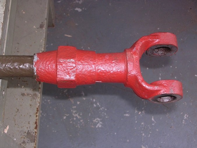
It was a bit of a puzzle to work out how it went together. There is a screw thread inside which must provide the adjustment but how does that nut work?

A closer look revealed a slot cut in the clevis. I decided that rather than being a simple lock-nut, the nut must have a tapered bore which squeezes the clevis onto the thread. Only thing to do was to try to take it apart.
Clamp it to the bench and get the blow lamp out.
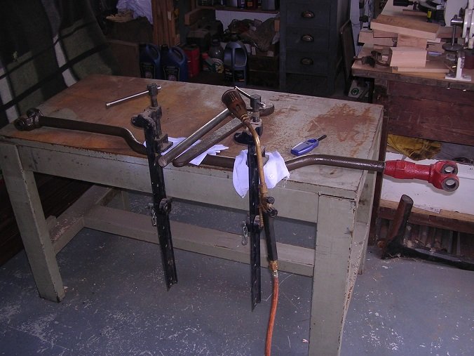
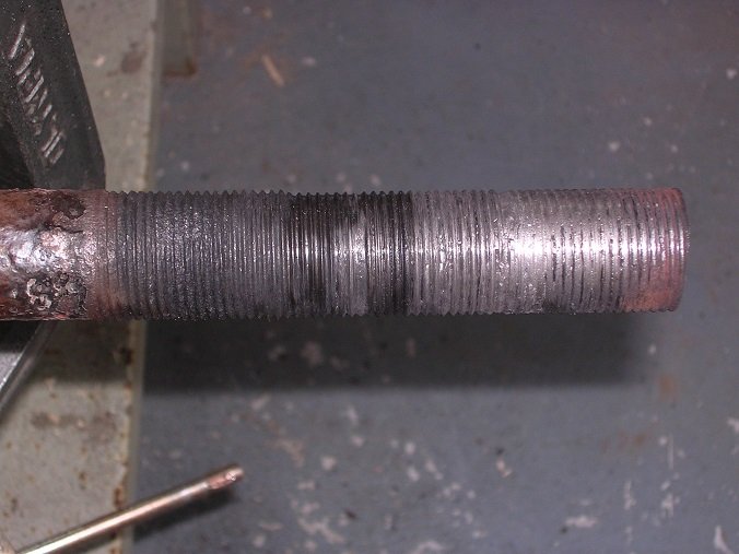
A bit of heave-ho with a big spanner got it moving but I could not release the lock nut. I therefore unscrewed them both together but, as you can see, this did the thread no good.

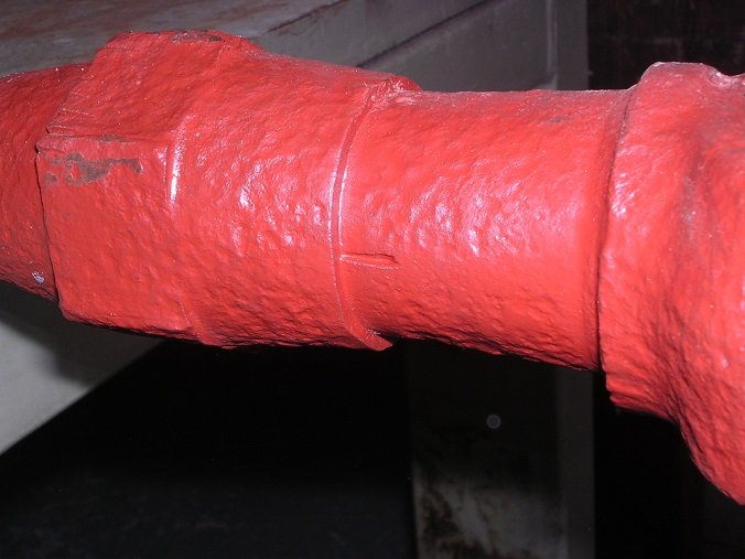
Some serious hammer blows broke the joint between the clevis and lock nut and the taper was revealed.

A wire brush soon tidied them up and they can be primed again.

My problem now is the thread. The engagement is very long so I am happy that sufficient strength will remain in the joint. However, the threads do need cleaning up. They are 1 3/16" x 12tpi which is an odd size again so now I am on a hunt for a suitable tap and die to borrow or buy. I don't want to start making those as well!
Steve
-
3
-
-
We took the track rod off again to see if it could be adjusted.
Now onto the back axle. The U-bolts at the rear are OK but access to the nuts is very difficult. I managed to find a deep 29mm impact socket which would do the job except that it was still too big in diameter to fit without fouling the axle. I put it up in the lathe and, running it slowly with a tipped tool, managed to turn 1/8" off the diameter which was just enough.

Back axle now secured to the limit of my strength with a 3/4" drive socket wrench!

The back axle is mounted on swinging links at both ends and is secured by an adjustable radius rod which allows the chain tension to be adjusted. This rod has bronze bushes at both ends which locate on bosses on the end of the axle and on a casting on the side of the chassis.

Dad had cleaned and painted two adjusters but unfortunately, one of them was very worn to the point that there was 1/4" clearance.

We had a rummage in stores and found another which fitted much better so we decided to use that instead. First job was to strip it down and clean it. Getting the lock-nut off took two big spanners, heat and some serious effort. All OK in the end, however.


To fit the radius rod assembly, the axle needs to be in the right place. It took a ratchett strap to move it though!

It dropped on nicely in the end. The locking washer will be secured once the chain tension has been set.

The brake back plate was fitted too. This was a performance again because it is on studs which are 3/8" UNS thread. We found enough nuts to clean up and fit it but are rapidly running out of these fasteners. I really don't want to start making up nuts if I can avoid it. Does anyone know where we could buy some UNS nuts in a handful of sizes please?

That was it in Devon for the weekend. We will have another get-together to do the other side in a couple of weeks.
Steve
-
2
-
-
Father had previously rescued and cleaned up some lock washers.

Wheels next! I fitted the inner race after greasing it up and then screwed in the locking ring. This has a grub screw in the joint to stop it unscrewing.

The two of us can just lift a front wheel so we put that on the stub whilst father fitted the other race.

The securing nut and some shim washers to set the end float and the wheel was on!


Dad had already cleaned and painted a hub cap spo that was fitted.

Coming on now!

Track rod next with Father's brand new pins.


After that was fitted, I checked the tracking and found that the wheels toe-in by 2". That is the rims at the front of the wheel at a radius of 15" are 2" closer together than the rims at the back. I think that this is too much and that a better figure would be around the 1/2" mark. What do you think?
-
1
-
-
Time to fit the front axle! We lifted it into position and balanced it on a stool while we fitted the U-bolts.


The other end was trickier of courseas the holes did not line up but with a little help from a bottle jack to push the springs apart, they went in. We fitted them with ordinary plain 5/8" UNF nuts, just nipped up for the time being until we can fit the overload springs.

New balls were fitted to the king-pin thrust races.


I fed the king pin through whilst Tim held the stub axle.

The king pin screws into the lower part of the axle and a lock nut is fitted.


On the top are two holes for a locking washer.

-
2
-
-
The U-bolts were supplied with 5/8" UNF Nylocs. We won't be using them!
Steve
-
4 hours ago, Tomo.T said:
Next problem is how to re create and attach the small finger grips that surround the underside of the wheel, originally these would have been formed with the celulose coating, any suggestions please chip in.
Hi Tomo.
Have a look at page 43 of our Thornycroft thread. You can see how I made the ribs from brass for the pattern. I glued them onto the timber but you could soft solder them on to a steel tube. Tedious but effective!
Steve
-
1
-
-
We have, as you might expect, been busy over the weekend and we will share that shortly. In the mean time, I have been doing some preparatory work to make up a second spring clamp plate as we have only one. Unfortunately, it is a bit of an oddity as it traps the overload spring on the top. Dad started the job by cutting out a base plate.

I then welded some bits of angle to hold the spring. Unusually, for me, the weld came out quite well. An expert would be critical but by my standards it was OK!

Some time with angle grinder and files and the result was quite acceptable.


The second spring will be a challenge. It is 7/16" wire with some really weird ends.


I have found a spring maker here in Leicester who will take a look at the job but I can't visit for the time being!
We have also taken delivery of some new U-bolts from Jones Springs who were extremely helpful.

They fit too!

More later. Watch this space!
Steve
-
1
-
-
The drums are mounted on the half-shafts where they exit the gearbox. The assembly method is to hang the box in the chassis and then insert the half shafts through the sprocket bearings and into the differential. The drums go between the box and the chassis rail on each side. There isn't room to insert a key in the shaft and then push it through the drum so the drum is simply split and clamped over the key and to the shaft. It makes a good tight fit and makes dismantling very simple. It will become clearer when we have photographs of the assembly.
Steve
-
2
-
-
Pattern making continues and now I am into core boxes. As you can see, there are two cut-outs in the back with return flanges, necessitating a core box each. The flange requires that the core protrudes outwards to create it.

This is the side of the box with the flange tucked underneath. I drew out the profile on the drawing board which helped a lot in aligning it all.

The front and side I glued together as a seperate piece. It must disassemble to be able to release the sand core.

And the same for the other side.

The whole lot is held together with over-centre catches. The water overflow boss was glued into the bottom.

The prints on the main plug and the two boxes. The right hand one has two bosses for water outlets.

Now onto the big core. I plained up some timber left over from a lorry body and the base is an old table top. Nothing is wasted in this household!

The filler neck requires a cylindrical boss so I glued up two blocks and screwed them together before drilling the hole.


The angles on the blocks were all cut on the chop saw. That is a marvellous tool. Nice straight cuts with controllable angles and the ability to trim them accurately to length.

I cut rebates at the corners and set some plywood over the joints to strengthen them. They proved their worth when I dropped one and suffered no harm!

A trial lay-out.

All of the loose parts were then dowelled together and secured with over-centre catches.

Just to add a bit more challenge, the inside of the tank has a baffle arrangement for the return flow. This puzzled me for a while but is quite straightforward as long as I can get the bits in the right place!

The main shape of the baffle is screwed onto the bottom board. The interior will be part of the fourth core, supported through the return flow hole.

All clipped together

Dismantled and pulled back from the core to aid removal.

One more core box to do. I shall be glad to see the back of this one. There is saw dust everywhere!
Steve
-
6
-
-
Hi Doug.
This is square on but the reflection is terrible!
Steve

-
1
-
-
They are re-decorating our production office at work and I got a call to say they were getting rid of an old picture and would I like it? It turned out to be a framed general arrangement drawing for the Dennis Subsidy A chassis! I took their arms off...

Steve
-
3
-
-
21 hours ago, andypugh said:
Did you consider that they might be chaplets?
Pretty sure they are not. They just look like surface marks as if something had been left in the sand. I have seen chaplets and they were much more obviously separate components. Also there is nothing obvious to support just there. I may yet be provem wrong!
Steve
-
22 hours ago, Rootes75 said:
Its a lovely read seeing this progress.
You are too kind. I am glad you are enjoying it though. It is the only reason for doing it!
Steve
-
Well, despite evreryone's kind thoughts and suggestions, I still don't quite have my head around the bottom tank even though it looks easier. I have, therefore started on the pattern for the top tank!

First thing to do was have a good look at it. No obvious part lines on the top but it had been polished at some time. The badge text shows signs of porosity which suggests that it was at the top of the mould during the pour.

An extra challenge in the shape of some internal baffling.

Two rebates on the back with undercut flanges.


Some interesting markings in the back of the casting which we eventually decided were 'chills' to freeze the metal and force it to draw more in from the riser rather than leave a void at this point.

After a good looking-at, I decided that it was cast on its back with the text upwards and a split, right through the centre of the filler neck. There will be four cores, a main big one for the water space, two smaller ones for the flanges on the back and a fourth small one to create the baffling. Time to make a start!
First task was to source some material. I was very kindly given what looked like the remains of a door and some wall panelling. Not very prepossessing to start with but under the paint was the most beautiful timber with straight grain and no knots. It had also been seasoned for 100 years and was beautiful to work. I did, however, find a nail with the bandsaw. Oh well. The blade needed changing anyway.

Prepared blocks being glued up.


I drilled right through and put some dowel pegs in to maintain the alignment of the two halves before cutting the profile.

The flange was cut from MDF and glued onto the underside.

Two blocks were cut for the back as core prints and a much larger block glued to the bottom, again as a core print. The large size of this one was decided upon to give the core some mass of its own and counterbalance the part projecting into the cavity.

OK. So the main block was done. Now I needed a pipe flange on the back and a badge on the front. I took rubbings of the originals before tracing the badge, scanning and printing it and sticking both to a piece of 1/8" plywood.

These needed cutting out so I rashly invested in a scroll saw. A good investment it proved to be as well.


Next challenge was to get the letters properly aligned on the front so I printed another badge but reversed this time. I glued the letters to it, just following the lines.


The result was then turned over and glued to the face of the tank before rubbing back with glass paper.


There are some bosses on the rear of the tank to carry the securing bolts but with the split line where it is, they prevent the pattern from being drawn out of the sand. A closer look revealed a clue in the shape of a line down the face. The parts must be removable loose pieces!

I cut out a rebate from the rear with a chisel and made up the loose pieces.


They work well and will remain in the sand after the block has been removed. They can then be drawn out individually.

Another core print needed. This time it is through the filler hole and will give support to the main core. I started by screwing two pieces of mahogany together before turning them to size.

I glued one half to the top. Notice the filler around filling a few holes!

I screwed the other half back on with a piece of paper in between before gluing the other half up to it.


Coming on now. The block needed a fillet along the flange so, at the recommendation of a pal, I ordered up some fillet wax and a ball tool to apply it. The wax comes in 24" lengths and is just pushed into the groove. It went very well but, I am told, it needs to be done on a good warm day. On a cold day it will crack unless the tool is heated.


Now I need some core boxes.
Steve
-
10
-
-
Hi Andy. That is remarkably similar. Thanks for that.
Steve
-
Yes, it is a two-cylinder engine but with a tee head so you would only expect two followers per side.
Steve
-
The plugs are to access the valves which are typical of a fixed-head engine. The Thorny and the Dennis are the same. The centre plugs must be a simpler way of sealing off the water jacket instead of a flanged cover with studs.
You are right, the apparent spare follower positions are intriguing. To someone who knows what the engine is, they will be the main clue!
It is amazing what is about even 100 years later.
Steve
-
Thanks for that. Worth a try.
Cheers!
Steve
-
A pal of mine has turned up this engine. Said to be a marine engine but of otherwise unknown provenance. Can anyone identify it please? It is a tee-head, is fitted with a clutch and looks to be of great war era to me.

Cylinder bore must be around the 3" mark so perhaps a 10hp engine? Your thoughts would be much appreciated.
Steve
-
Looking good!
Did you put the spring on any sort of pad? I have often seen springs seated on a red fibre pad but never understood why this should be. I have had great difficulty in sourcing any sort of replacements for them and have generally done without.
Steve


")

")


WW1 Peerless lorry restoration
in Pre WW2 vehicles
Posted
Can't leave Dad to have all the fun!
Now that the front wheels are on along with the track rod, king pins and stub axles, the king pins need some greasers. We are fortunate to have the remains of three but, of course, we will eventually need four. They screw into the top of the king pin and , when the knob is turned, a piston is driven downwards expelling the grease and pushing it down the hole in the king pin. I took them apart for a clean and to assess what parts were missing.
This was the most complete example having both the knob and locking clip.
We have two pistons which have leather seals.
The internal springs have ends bent so that they locate inside the cylinder and in the top of the piston to stop it rotating as the knob is turned.
For a bit of light relief, I filed up the three missing clips.
The fourth knob was next. A rummage in the stock drawer found alump of brass which would just do with a bit of judicious hole-dodging.
Roughed out and with filing guides bolted on.
An hour or two with a file and emery paper and there is a respectable replacement.
Of the three centre spindles that we have, one is wobbly in the knob and has a poor thread. As usual, the thread was a UNS example but this time left handed! I don't have a die for that as you might expect. However, 3/8 UNS has 18 tpi but 3/8" Whit has 16. I opted to make the two replacements with 3/8" LH BSW threads. Well, there is a limit!
We are missing two pistons. They were a simple turning job with a LH thread in the middle. I have used O-rings instead of leather washers and I am sure they will be fine.
First complete original cleaned up and reassembled.
We have only three original cases so I had to turn up the fourth. A rummage in the stock drawer turned up a 3 1/2" length of 3" brass bar. I have no idea where it came from but it was absolutely just right for the job.
Lots and lots and lots of swarf with a bit of knurling thrown in.
The excitement of parting off without damaging it.
The slot for the locking clip.
Pinning the knob to the spindle. I turned up a pin and tapped it into the hole before peining the ends over and dressing off.
Nearly there now but still missing a spring for the new one.
I wound this on a tapered mandrel. Unfortunately, I didn't allow enough for the spring to relax at the small end as it moved more there, reducing the net taper.
Not quite perfect but I think it will do the job.
Final assembly.
The final three cleaned up and assembled.
The fourth one is already on the lorry!
It is amazing how long these silly little bits take. Fortunately, the remaining greasers are a lot simpler which is good news as there are dozens of them of a special Peerless pattern!
Steve")