


Old Bill
-
Posts
1,661 -
Joined
-
Last visited
-
Days Won
33
Content Type
Profiles
Forums
Gallery
Blogs
Events
Articles
Store
Downloads
Everything posted by Old Bill
-
Now that is gorgeous! What a find! Steve 😁
-
With my recent experience of the Peerless radiator, I think the solution is to dip the tubes in solder. This would get into every joint and seal up the edges of the tinplate to prevent rusting. It needs to be done fairly soon after assembly so that all the components are still clean. I must admit that I didn't fancy setting up a dipping tank myself so the guys at CPA did them all for me at £3.50 a tube. I didn't see it done, unfortunately, so I can't offer any tips but he did say that the tubes were 'acid dipped' first. I take that to be in Bakers fluid but now I am guessing. I know you are very independent but sometimes, it is worth buying in some expertise! Steve 🙂
-
Hi Barry. Yes, my mill is operational again. It has a three phase motor driven by a variable frequency inverter from the single phase. All very convenient for me except that the inverter died. A pal of mine very kindly investigated it and fitted a new inverter for me so all is well again! Steve 🙂
-
Thanks for your thoughts Bill. After all of our previous projects, we expected to have every tap and die we could possibly need but alas, not. It just needs us to pick a French lorry as the next project and then we will have to get metric as well! On the subject of bolts, Dad has acquired all of the bolts to assemble the tanks and has machined the text from the heads so they are ready to go. However, as we expected the tank to be American, they are all UNF instead of BSW! I am using them anyway. I don't think there is a 'right' way for this lorry! The bottom tank was easy. All of the holes lined up and it was just a case of going over them, one after another to keep nipping them up a bit more until they were all tight. I turned the rad over, which was a bit of a performance as it is getting heavy, and then tried the top tank. As you can see, the tube plate wasn't flat by quite a significant amount. I briefly tried pulling it down but it wasn't going to go that far so I resorted to adding another layer of cork gasket at both ends. I feathered the ends of the gasket off using the sanding drum on the Dremel which worked quite well. A good layer of Heldite liquid sealant before bolting up and all was well. dad looked out the hose fittings and has cleaned them up ready for fitting. That is all most pleasing and a nice complete sub-assembly in store for when we are ready for it. I think we need to return to the wheels again and try to get the brake drum off so the wheel can go to the wheelwright. I dearly want to get it mobile! Steve 🙂


-
Dad did the tanks some time ago and they have been sitting in my living room for the last few weeks awaiting the core. The overflow pipe should be soldered into a brass fitting which is then mounted in the back of the header tank with a nut. First task was to identify the thread which turned out to be 1/2" NPS which taps and die, I didn't have of course. Soon remedied and the die is WD marked and 1952. I think of 1952 as recent but it is almost 70 years ago! A general clean up and re-soldering and I turned up a new pipe nipple for when we are ready to install the overflow. Now the bottom tank. Back to thread identification again and this time they turned out to be British imperial so the drain plug is 1/2" BSP. This seems odd but I eventually twigged that the tank is an iron casting marked on the back 'WD Peerless' which suggest to me that it came out of one of the ASC workshops and probably collected British imperial threads. This lorry will be a nightmare for whoever ends up with it in the future! 3/8" BSW! The flange face was very pitted so I took the opportunity to give it a skim. 1/8" BSPP! New stainless steel studs and a new gasket and ready to go. Same process again for the top tank. Fitted the overflow with the tube end up near the top. I had to drill out the remainder of the studs and tap them through again. I went right into the water space to get enough thread depth. New gaskets and ready for the grand assembly! Will this be straightforward or will there be some more pitfalls. I wouldn't put much money on the former although it should be easy. Famous last words! Steve🙂


-
This week's excitement has been a trip to CPA in Grantham to pick up the radiator core which has been dipped and soldered up. When I say soldered up, I mean it! That solder is 3/16" thick! It all looks sound though and he even painted it and cut some gaskets which I wasn't expecting. Nice guys to deal with and they did what they promised when they promised so you can't ask more than that! Steve 🙂


-
Thanks for your thoughts, Doc. I have never seen the process described before. We will just have to wait and see now. Next time I go down I want to drop it into the flywheel and see how well it fits. Bluing it and dressing off the high spots might well be the solution as I don't think it will be too thick, just not very round. I'll keep you posted! Steve 🙂
-
We are in the process of making a puller to get the brake drum off. In the meantime, Father has been pressing on with the clutch. Once he got home, he tried wrapping it around the band. Fortunately, we had got the curve about right. Then he drilled the holes through. We were a bit suspicious of drilling leather but he tells me that it is fine if you just let the drill take its time. He did have a practice first on an offcut though! After trimming to length, he fixed the leather with copper brake lining rivets. It all looks very nice but Dad tells me that the leather looks a little thicker than the original. The question is should we just try it or should we attempt to true it up by turning in the lathe? We haven't played this particular game before! Steve 🙂


-
Thanks Niels. Certainly our lorry and we have some very similar books on file. Let's hope they find a good home! I am pleased to report that we did 37 miles on Sunday around the local villages and Tim has had his first driving lesson! He didn't do badly but needs some more practice with the gearbox. Now we can take two out at once! Steve 🙂
-
It certainly has some Dennis stye features but it is not a subsidy type. It would have been nice to see the hub cap. The most exciting thing is that it appears to have the differential cover in place so the diff may be there. Interesting! Steve 🙂
-
Yes, it doesn't look much different apart from a year's dust all over it! The line is essential as I have 1 1/2" each side of the wing mirrors and if the back end is off by a couple of inches, I will either foul my compressor or make it difficult to walk down the side. It could really have done with being about three feet wider but nobody has a big enough shed do they! Steve 😄
-
Home straight now! I have been assembling all the bits. firstly by fitting studs.. They were too long! I went back and checked the originals and they are identical so not sure what went wrong there. I took them out, threaded them a bit more and shortened them before fore finally fitting them. Then I got to the end ones and they were too short! They are identical to the originals but then I remembered that two studs had no nuts on them. I have made new ones. And for the top tank. This time, I cut the main gasket first. This is from rubberized cork, as recommended by Steve at CPA radiators. I treated the gaskets with 'Heldite' which had been recommended to me. It is very like the old 'Foliac' jointing and smells pretty bad. Works OK though. Then the water return. This time the studs were too long. I don't know how I managed to make such a mess of them. Oh well. And the filler neck after a bit of Brasso. The core still carries a lot of water stains so I had a go at cleaning it with soapy water and a scrubbing brush. This morning, I fitted the side castings and stuck the gasket down with Heldite. Amazingly, all of the holes lined up. Even more amazingly, the holes lined up in the bottom tank as well and I didn't have to poke a drill through any of them which was most satisfying. Turn it over and on to the top tank. That fitted OK as well so really making progress now. The moment of truth. Will it fit? The answer was no! The radiator tie-rod eye fouled the underside of the bonnet frame. I don't know how I managed that but in the end, just sprung it up and over the top. Spot the deliberate mistake! I fitted the outlet spigot the wrong way up! That was soon sorted and I cleaned and fitted the return pipe and the overflow. The rest of the engine is still filthy but that is a job for another day. The moment of truth! Filled to the brim with water coming out of the overflow but no leaks. Amazing. A whole lorry again! I swung it and it fired on the fifth compression which isn't bad after standing for over a year. I let it idle until everything was hot and no leaks showed themselves. We have a lorry again! Next job is to give it a good service and a thorough clean and out for a test run. Let's hope the weather is nice again next weekend. Steve 😁


-
We are still doing battle with the wheels. One is still attached to the chassis but Dad has been working on the other. The wheelwright has had a look and stated that this wheel isn't bad but needs new felloes. We need to prepare it and then deliver it to him. Dad has spent a lot of time knocking out bolts. They are an interesting variant of the coach bolt. They are all a boit ropy so Dad has turned up some new ones (9/18" dia, just to be awkward) from some M16 bolts. The brake drum is not very well either. An attack with the wire brush has shown that the surface is too far gone and must either be skimmed or replaced. Fortunately, we have a spare in the collection and some attention with the flap wheel showed it to be serviceable. So, we have to get the old one off. My best find at Beaulieu this year was this pin spanner. Perfect for removing bearing nuts! This wheel still weighs coming on for a couple of hundredweight so we lowered it onto blocks using the chain block. Then we tried to knock the drum off by hitting it between the spokes. Not a hope so out with the propane. Some further knocking cracked the joint and two days of hitting it have moved the drum an inch where it has stuck As neither of us is really up to sustained hammer work, we have given up and are now ordering up the steel to make a puller. Once the drum is off, the wheel can go to the wheelwright. Then we have the next fight which is to get the second wheel off the axle. I shall be glad to see the back of this job! Steve 🙂 Like


-
Well spotted Chaps! There is a crack from the centre hole to both stud holes. I think they were caused by the mild steel stud corroding inside the hole and corrosion product build-up. There is a gasket on both sides of the plate with one side facing the aluminium top tank and the other, a cast bronze spigot which carries a rubber hose. I am not quite convinced about its being a sacrificial part as that would depend on surface area in contact with the water which, in this case is quite small. Whilst the surface was suffering a bit, it was nothing like the inside of the tanks. They went predominently next to the brass tube plate. It has certainly prompted some interesting thoughts and I can't see why they didn't just put a bit more metal on the pattern. I don't think the cracks will cause me a problem but it will be easy enough to replace if necessary. I have, however, made the replacement studs from stainless steel so that should slow the corrosion down a bit. Steve 🙂
-
Thank you Barry but you are far too kind. The last few pieces now before reassembling the thing. There is a strange aluminium spacer on the water pipe flange. This was corroded so I put it in the chuck and gave it a skim to clean. The last part was the radiator stay bracket. This is just an eye bolted into the top tank. Unfortunately, the original was just mild steel and broke off so I elected to make a new one from bronze. It was tough old stuff! Drilling bronze is horrible as it grabs the drill as it warms up. I managed to stall the mill with a 3/8" drill before I got through. The end has a nice radius which I machined as a series of flats before cleaning with a file. Unfortunately, I had to use my old mill as the nice new one has expired! Some sort of electrical fault which needs investigation. I wonder if the drilling upset it? Anyway, the result is nice and I made a brass nut to go with it. Reassembly next! Steve 🙂


-
I think they are using a CO2 setting sand but I don't know what it is called. I understand that to get a better finish, an oil bonded sand would have been much better. Never mind, they have come out OK and the cleaning up process is just my time which is free. Mind you, I am pleased to report that I have finished polishing! I have been tackling the top tank, first with a flap wheel on the angle grinder. Then with coarse emery on a sanding block to pick up the high spots and finally, some 600 grade emery with a few drops of WD40 to act as a lubricant. The WD40 was a very good idea and give a nice fine finish without tearing up the surface. Flap wheel on the last face; Finally, I have picked out the letters. I will need to run the sanding block over them again to pick up the ragged edges but, essentially, the tanks are done (thank goodness!). Now it is a case of cutting gaskets and fitting the studs before final assembly. The end is in sight! Steve 🙂


-
One of the jobs we have been doing in parallel is to take a look at the clutch. This is a cone clutch with the female shape machined within the flywheel. The male part is an iron casting with a lining. As you will observe, the lining has seen better days. Interestingly, the lining is attached to a steel band, bolted to the casting. Father removed the lining ring and had the centre sand blasted before painting both. He removed the lining from the steel band and found that it is of quite interesting construction. It is, in fact, a leather band with plugs of cork inserted at regular intervals. The chances of us finding such a material are slim so we have elected to simply replace it with leather. One of my lorry friends came up with a piece of leather for us, the right thickness and just big enough. What you can't see is that it has been stored in a very dry environment for a very long time and was absolutely as hard as a board! Mark, our leather working friend, was contacted for some advice and he suggested painting it with Neatsfoot oil, letting it soak in until it would accept no more. Dad bought a pint and I started painting the outside. I couldn't get inside as it would not unbend, initially. However, after a week of treatment, I managed to get to the other side and carried on. Eventually, the sheet absorbed almost the full pint of oil that we had and had softened apprecialy. You still couldn't wear it but it was flexible enough for our purposes. I cut out a template so that when cut, it could be wrapped around the conical liner ring. Half an hour with a Stanley knife saw the strip cut out. Dad has now taken the strip home to rivet to the lining plate so we are still making progress! I am delivering the radiator components to Grantham tomorrow for solder dipping and soldering into the tube plates. Steve 🙂


-
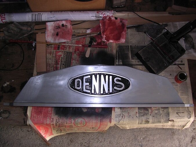
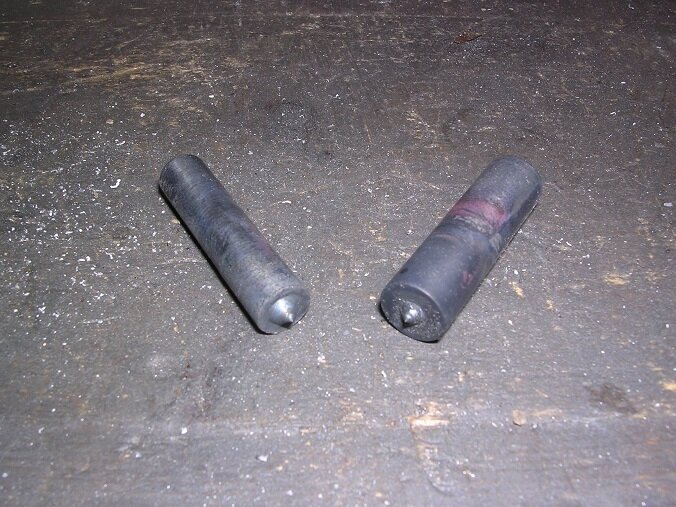
Thanks Barry. I have thought about investing in a buffing machine but my experience has always been that it is very difficult to maintain a crisp edge with them. As the crisp edge is such a feature of the Dennis rad and this would be the only big job I would have for one in the foreseeable future, I have desisted and had a go with a flap wheel instead. I did the back with a wheel in the pistol drill, keeping it moving to avoid grooving. That was fairly painless and I finished off with some emery in my hands. The badge was some coarse emery on a flat sanding block and it came up quite quickly. Then I had a go at the front. The flap wheels in the drill and in the angle grinder certainly took the surface off very quickly. However, it took a great deal of care not to groove the surface and then a lot of hand-rubbing with emery to take out the marks. So far it looks pretty good but will need some fine wet-and-dry paper to finish it off. Tedious but coming along. Of course, the big top surfaces remain.... As a bit of light relief, I thought I would make up the replacement studs. I have given in and used stainless for them as the originals have corroded so much and couldn't be removed. Studs are something of a pain, I find, as they are such devils to hold. The first end thread is easy but the second always difficult. To hold them whilst cutting the second end, I made up this holder. I have tried in the past to put a thread right through and simply back up the stud with a bolt but, unfortunately, this didn't work very well as both stud and bolt tended to screw right through when cutting the thread. To get over this, My locking bolt has a finer pitched thread than the stud so the stud cannot screw in during the cutting process. Once the thread is cut, simply back off the locking bolt and the stud will unscrew. This is a good trick to know! All done and I am getting closer to reassembly now! I have some cork gasket on the way for the main joint and am trying to pick up some jointing compound. I think it is going to have to be mail order again. Steve 🙂


-
My trip to Grantham was successful and I picked up the extra ten tubes and 3000 gills. They are now all threaded and ready for another trip to deliver them for soldering. 136 tubes and 16000 gills with a few left over. All threaded by hand one at a time. My fingers are sore! Steve 🙂

-
A bit more progress on the Peerless. Dad has continued painting the cylinders. The valve guides remain to be reamed and new valves obtained but after that, they can go back on the engine. Dad has been to visit and brought the radiator tube plates with him. We decided to see how easy it would be to just melt the tube ends out and found, much to my surprise, that it was effortless. Once warmed up, the ends could just be tapped through. I turned out that they were not a close fit in the plate at all but were really quite sloppy so there were no problems. A quick dressing back afterwards followed by putting a 'W' drill through to clear out the gobs of lead and they are ready for final assembly. I am off to Grantham again on Monday to pick up the extra tubes and gills. Once they are assembled I shall go again to deliver the kit for final assembly. Steve 🙂


-
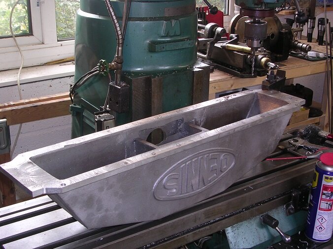
Had a nice day in the shed today. To carry on the job, I need some bolts so I cleaned up all of those I took out. Very tedious! To align the holes between the tube plates and the tanks, I have turned up some transfer punches from silver steel an hardened them. I marked the first two holes and drilled them before bolting the tank to the tube plate. I then went around marking the other holes. Set up to drill on th emill. I marked each centre pop with a pen as I have been caught out before by drilling a casting inclusion instead! Then the same for the top tank noting that some of the holes are for 3/8" bolts and some are tapped for studs. There is another opportunity to get it wrong here but fortunately, I was concentrating hard enough. Both tanks are now finish machined and it remains only to polish the surface of the top tank. Unfortunately, the casting finish is very coarse which is disappointing. This will make the job very tedious. I did ask if they could use a different sand to get a finer finish but apparently not. Oh well. Back to it. Steve 🙂


-
It is a DSG toolroom lathe. Not immense capacity for its size but very heavily built. It came out of industry not too heavily used and two members spent several days cleaning it up and repainting it. It now looks like new and is a joy to use. It is a great facility to have because I just couldn't justify having one myself. Steve 🙂
-
This earning a living rather gets in the way but I am making some more progress at last. There is a flange for the water return on the back. It was a puzzle how to hold the thing again and it was not particularly secure. However, with light cuts, I got away with skimming it before drilling the stud holes. The last operation before tackling the bolting flange was the overflow. For some reason, this enters the rear of the tank at a really awkward angle. My lovely new mill has all sorts of adjustments and it worked out OK in the end. What a joy to use! Of course, tapping it was tricky too with no space for a tap wrench. Fortunately, I found a socket which fitted the tap although it took a lot of care to get the tap straight. The end bosses on the bottom tank needed turning and I am fortunate that my local miniature railway, the Echills Wood Railway has a big lathe in the workshop which I could use. The wooden bungs in the ends worked out well. A trial fit on the core looked promising. Today's job is to mark and drill the bolt holes. More later! Steve 🙂


-
More progress at last! I have started on the castings. I gave the bottom tank a skim to square it up. Then a skim across the joint face. The foundry had been concerned about shrinkage and so had made the flange extra thick and I had to take 1/4" off it. It all machined ok though. It is an awkward thing to hold but I managed to skim the water outlets and drill and tap for the studs. The main tube plate holes and the spigots remain. To turn the spigots, I have driven in some mahogany plugs and have centred them ready for turning. Ijust need to find a big lathe now! I started on the top tank this morning. Again, it is a most cussing awkward thing to hold. I could only grab the end flanges but although big, the casting is quite thin and not very strong forcing me to take only very light cuts. Why is it that no matter how big your machine tools may be, you can always find something a bit bigger than it is intended to work! The table does not have quite enough stroke so I had to machine the tank only so far before rotating the milling head to the other side of the centre line to catch the last four inches of the casting. Irksome but it all worked very well and remained aligned. I have drilled and tapped for the filler neck. As you can see, the casting is a bit shy of metal and could have done with another 1/8" on the boss diameter. I shall have to remember that for next time. It doesn't look out of the way, fortunately. Tube plate flange holes next. We should be back on the road in no time now! Steve 🙂


-
Thanks Barry. Might be worth a go. Looking at these photos this morning, I have just realised that there are ten more tubes in this plate compared with the one I counted before placing my original order! Will have to get some more tubes as well. Oh well. That's a job for later. I am on Dennis radiator castings today! Steve 🙂


