


robin craig
-
Posts
3,691 -
Joined
-
Last visited
-
Days Won
2
Content Type
Profiles
Forums
Gallery
Blogs
Events
Articles
Store
Downloads
Posts posted by robin craig
-
-
Apart from the cost, why would you not want to have a vehicle carrying such a weight sent for an MOT?
I realise I am in a foreign country so I might be missing something.
Robin
-
I know these are slightly off topic but here goes anyway.
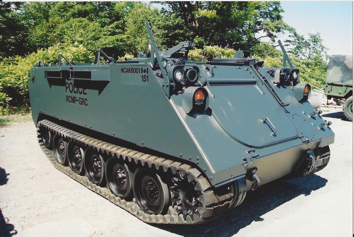
The Canadian Forces over the years have passed possession of a number of military vehicles over to various law enforcement agencies over time.
A number of years ago some M113 and AVGP and Lynx were sent to the Technical and Protective Operational Facility of the Royal Canadian Mounted Police (RCMP) outside Ottawa, Ontario, Canada. From what I can ascertain they went via a local contractor DEW Engineering who serviced them and removed various bit and in the case of this one painted it and marked it up and changed the track system.
If you are wondering about the marking "RCMP-GRC" in Canada we have two official languages English and French and anything Federal gets marked accordingly, the GRC does not mean Government Racing Car as some alledge, it stands for Gendarmerie royale du Canada.
Apparently it lacked the rumbling presence with this rubber track and lacked the psychological effect they were hoping of at an incident. In later life it was equipped with a barricade up front that could be raised and lowered and had hydraulicaly operated wings and see through panels in the upper portions.
Once day when i find the rest of the images I will post them.
Hopefully a scale model maker will find these interesting.
They are my images so please ask me via email before plastering them around.
Regards
Robin


-
Great find, shows how useful gear gets kept as it works for a living.
Look forward to seeing how it cleans up
Robin
-
Here is a link to some more discussion on the same vehicle
Robin
-
It has been a while so I thought I would drone on some more and let you know what has been happening.
We only work on the vehicle when time allows, this is not a primary work project.
I have tidied up the interior and have been painting it, I find a 2" wide foam roller really gets in everywhere very well. Very useful tool.
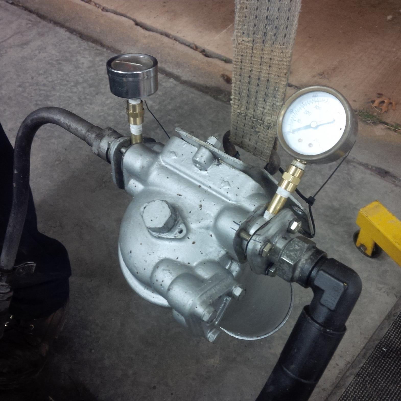
We found problems with the wheel cylinders and the master and sent them out for sleeving in stainless. Expensive at $1500 dollars all taxes and delivery in, but it is a lifetime cost for the vehicle. Again, we used John Stuart Power Brake to do the work.
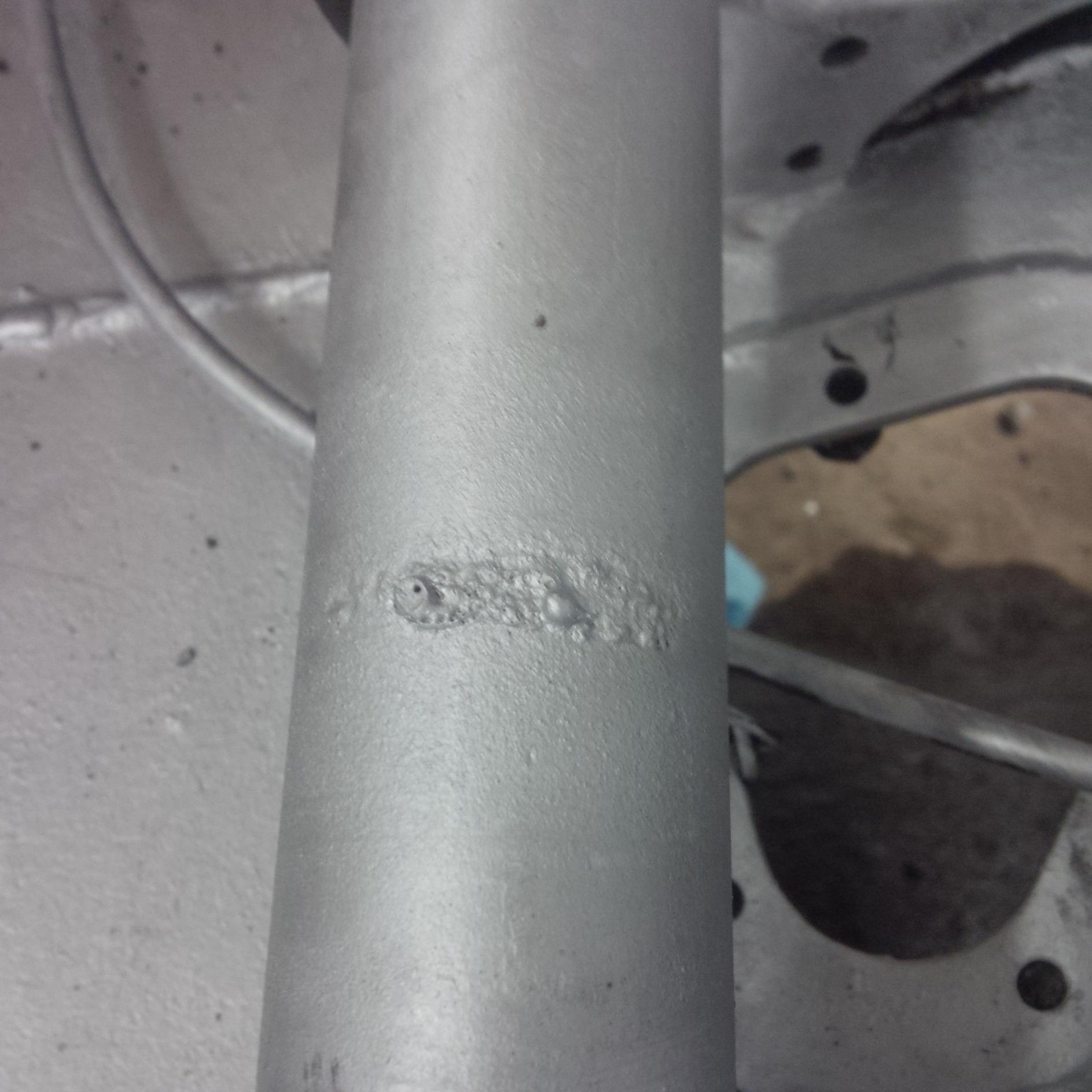
We found a previous owner stupid trick when we were tidying up the power pack. In a previous incarnation the power cable to the starter had been spliced using a cobbled together goofy hacked down battery post terminal and covered poorly in tape. This had arced out on the rear right drive shaft. We have now repaired that with a proper connector as replacing the terminals on the end wasn't an option at this point.
Anyway, the brake parts are back and I am going to refit the master before sliding in the pack, which may happen this week or may have to wait until after my holiday, which a week from now I will have started.
We have also run up the pack and proven all is well there.
Robin


-
You are correct I believe, there are murky images on obscure sites showing Mk7s in service in places like Singapore and in a museum in the USA to name two places.
Robin
-
I have uncovered an amount of info on an Albanian army website which has provided a wealth of information.
I had hoped to acquire a copy of a parts manual but with the info from this webpage and by capturing the various images on their own and enlarging them there is enough to get us going now.
Add to that the kind help from Sirhc who has found a few pairs of track for sale and I think all we are missing is time and money, so should be an instant project in the next 10 years.
There is enough info from the images to reverse engineer a very close replica now.
I am very happy
Here is the link
Robin
-
Clive,
the ad says 200 Tdi, is that not a failure prone engine or is that just myth?
Robin
-
Welcome along Andrew,
show us what you had or still have
Robin
-
John,
your post interests me hugely for a number of reasons.
I am in one role a welder and fabricator, in another role an MV person.
I always try to ask myself, "If I had been asked to do this back then with their technology and their need for a bang for the buck how would I have done it"?
So, let us take this apart step by step.
Firstly, the assertion that the end connectors were welded to the hull, show me a detail part of that photo where that happens?
The end connectors, if I read you correctly, hold the pins that unite the track sections. The track is shown upside down against the vehicle, the guide horns that the road wheels align to are the point of contact. That also makes for a
'stand off" type armour whereby the round explodes on the expendadble track sections and not against the hull and thereby has value.
To cut off all the guide horns to bring the end connectors in contact with the hull is a labour that no sane person would have done, by my reasoning.
Far more likely is that the guide horns themselves are the point of contact against the hull and they were the item that were tack welded to the hull. one weld per guide horn on either side about every 5th track link would have held it on nicely with minimal burn damage inside and a quick job.
If you have weld marks check them against the guide horn spacing, that will be the proof in the pudding.
I have been wrong before, I am not a WW2 kind of chap, I am just trying to bring reason to a very good question that I thunk has gone off the rails.
My 2 cents worth, I am not trying to offend just trying to out the truth by reason and proof.
Robin
-
I know, don't ask how, let us just say I have eagle eyes (and many scars) of an Eager Beaver that may be for sale in Scotland, yes I know I am in Canada.
I am posting it in here as many have been watching this thread.
I am not related or connected to the seller and know nothing more than it is an Eager Beaver and his contacts
Robin
-
To be clear, the vehicle I showed has nothing inside it in the way of drivetrain.
R
-
Wonderful document Clive, thank you once again for doing that for the rest of us.
I had thought I had seen something along those lines but could not remember where.
Thank you
Robin
-
I think you are not getting replies because perhaps like myself people do not quite understand the question.
It sounds like you want to winch a Land Rover into a garage that has a 30 degree slope outside. Is that the question?
My questions are:-
1 why can the vehicle not drive in under it's own power?
2 where is the winch mounted and what powers the winch?
3 Perhaps a picture of the garage and approach area would help us
Regards
Robin
-
Can anyone shed any light on these two for me and let us have a bit of a discussion.
Were they only BAOR used?
What fuel were they for?
What era? What came before and what followed after?
Thanks in advance
Robin


-
Agree on what the others say . . . . unless . . . .
You have the time to do what I did but strictly for non operational purposes, no shafts connecting anything and slow speeds used.
This is what I made for mine and used with CVR(T) A bars.
Robin


-
Brilliant Wally,
Thank you very much, once again this forum triumphs over the evil Facebook and comes up trumps with the answer, hooray!
I have passed it on to the people who have her now.
Robin
-
Can anyone comment on this please?
The Inniskillings Museum has a 1974 series 3 half ton landrover (02GB74) and they have this under the bonnet.
Is there any way it could be original?
Robin


-
There was a vehicle such as that in the horde of vehicles at the B & E Boys storage facility that I visited, some kind of story about why it didn't have a gun that was a lot less plausible than the driver training vehicle usage you describe.
Of note, the Land Rover gong past the Abbot also seems to be ex military.
Robin
-
Yes please, I am trying to buy one myself and have a big soft spot for them, and besides, there are lots of other vehicles likely to appear in the background.
Robin
-
I don't know for sure, so some would say I should shut up but here goes.
The AFV crew tents seem to be all cut from the same design cloth, in as much as they are a shed roof like design and the higher side gets tied off to the vehicle.
The lower side has the small poles and from near their top a guy rope extends out to ground level and a peg. That is what I am familiar with from the CVR(T) tent.
I think this thread may hold some info of value
http://hmvf.co.uk/forumvb/showthread.php?39695-Chieftain-tank-crew-tent
Does that help?
Robin
-
Rob I am so very happy for you now that you have the correct number for the vehicle.
I see the day that it is not driveable coming soon as you strip things down.
Robin
-
Welcome to the forum, pictures required to really complete your introduction
Howdy from Canada
Robin
-
Spot me the flight I will be there mate;):-D
Robin


restoration of a valentine MK5 tank started
in Tracked vehicles
Posted
I am interested to see the hull on it's side, was that better for painting the inside? I am considering dong that for a project ahead of me.
Will you be replicating any data plates at all?
Great progress
Robin