


Andrew Rowe
-
Posts
309 -
Joined
-
Last visited
Content Type
Profiles
Forums
Gallery
Blogs
Events
Articles
Store
Downloads
Posts posted by Andrew Rowe
-
-
From trash to treasure. The complete steel conduit wiring loom ( except front headlights ) laid out ready for blasting and painting. We have worked out that we can feed 99% of wires through the conduits outside of the Tank on the bench, so will save our knees! Also it appears we can install in basically 3 major groups of pipes. The L/H side wall pipes , the turret floor group as one and the engine bay , also basically as one complete unit. Cheers from The Tank Factory


-
Sorting out spaghetti junction! , steel conduit for the inside wiring looms. Mostly 1" dia. with a bit of 3/4' throughen in for good measure. Have decided to paint the conduit pipes black, as original manufacturing finish. Cheers from the Tank factory.


-
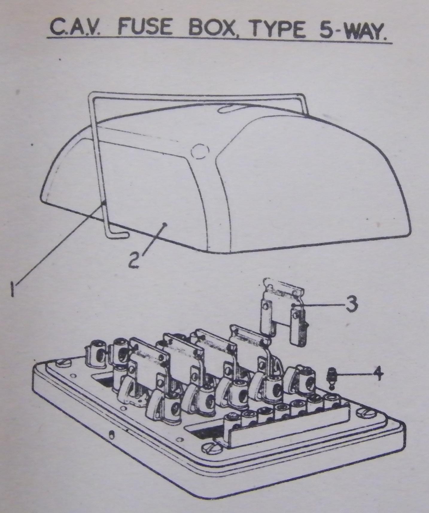
Finally, the "holy grail" of fuse box covers has come to the surface, yes I have found a NOS number 5 fuse box cover for the restoration. It is also interesting to note that these come in bakerlite or a type of alloy / gunmetal casting. The last pic shows the " A " and " B " radio mounts that sit on top, at the back of the turret. Cheers from The Tank Factory.


-
The last couple of weeks or so has been dedicated to the detailing of the engine. The first picture is viewed from the rear of the engine, it shows the water pipe to the bottom radiator tank, luckily we have some NOS pipes , as the bends are quite tricky then the gearbox & bevel box breather vent pipe, and also the 2 main fan blades. The L / H one is marked up as NS ( near side ) and the R / H one OS ( off side ). These 2 blades suck air from the fighting compartment through the radiators and out to the rear of the tank. Important that they are put on the right way !
The 2nd pic shows the manifold for the 3 air cleaners with the emergency stop cable coming down from the govner to shut down the blower if needed. If this is used it can potentially suck the blowers seals inwards, I have heard, but if you have a run away engine, I think that is the least of your worries. We have also installed a fuel shutoff valve as backup in case the fuel ever needs shutting down as well... but as often the case if you need to get to this, you have to rotate the turret 90 degree and then lift the engine decks in the right sequence to find it!
The 3rd pic shows the front of the engine where the oil and temp outlets start from.
The next pic shows the near side of the engine with the generators, 24 volt at the front for charging the batteries, then the 12 volt one for generating power for the turret traverse, then in behind this one you have got the coil and spray nozzle for the cold starting into the air box and also tucked against this is the suppression unit for the turret generator, where the cables run through and then into the main wiring loom. Oil bypass filter hangs at the back also.
The 5th pic shows the top of the engine at the back where the thermostat housing is, before it will enter the top radiator tank.
The last view shows alongside the generator setup.
Cheers from The Tank Factory.


-
The clutch and gearbox are shown being mated up. The clutch is a single dry 15&1/2" plate. Also new pilot bearing for the main shaft was installed. Clutch cover held on with 3/8 UNC bolts @ 40lb torque. Spline on the main shaft slid into clutch easily. Cheers from The Tank Factory.


-
Shown are engine blower and water pump and govern control unit on the R/H side of the engine. The blower forces a constant volume of air to the cylinders , which when the piston travels down the liner it uncovers a row of slots around the liner that takes in air back up to the combustion at the top of the piston. I think the constant pressure is only about 5 lb., but it is all about forcing volume in. Also shown is the flywheel about to be mated to the crankshaft. Cheers from The Tank Factory.


-
We have received the engine back from the machinists. Now we can start bolting on all the extra's to build it up to spec.Cheers from The Tank Factory.


-
Thanks Rick, interesting option for the track. I blasted and painted Scorpion track years ago, and after running around a day or so it "blended" in quite nicely also.
Hi John , every nut and bolt on this project is either subjected to bead / sand blasting, depending on sizes, also wire bushing on a mechanical wheel , and also we treat nuts and bolts in the molasses bath. These are all coated with etch primer , and also the shaft of the bolt is greased with our special anti corrosion paste when assembling. All treads have a die or tap run over or through them. 99% of the bolts with nuts on only have one or two threads sticking out past the nut, to avoid corrosion, wheels nuts have a full nut on and that's it. The final top coats of paint to the head or the nut will happen once the Tank has completed it's trials and tracks come back off and the hull will be prepared for the final painting sessions.
Sometimes it may take a day or two just to resurrect the original nuts and bolts for just one assembly to get bolted on , just depending on quantity required. The wheel hubs alone require 168 for the rim and 126 to hold it on the hub, that is for nuts and also for bolts. The main wheel station steel work that bolt to the hull take at least a day each to bolt on in the right sequence. The photo's tell a story that looks simple but cover up the behind the scenes work on the mounting hardware.
95% of all hardware is BSF for the Valentine, Cheers Andrew.
-
Track laying done. The Valentine's tracks consist of 103 cast shoes per side, they are directional, in that where the forward movement is engaged on the sprocket the track shoe casting is thicker where the sprocket "grabs" it to thrust the Tank forward. The track material is high in manganese, which is not magnetic. We have put the tracks on in their rough cast form, so am debating whether they will be blasted and painted black when they come back off after road testing the vehicle for final clean down. Track tension will be obtained by rotating the eccentric front hub , to get approximately 3" of total up and down movement between the top rollers. Cheers from The Tank Factory.


-
Yes, Nipples all polished !, like little gold nuggets, to be fitted. Tank now lifted off blocks awaiting "Track laying" in the next few days. Cheers Andrew.
-
I have wheelly good news , the wheels are on !:laugh: Cheers from the Tank Factory.

-
The suspension on the Valentine is built like the proverbial brick____house, so have never come across any issues. There were some cracks found in one or two of the small needle roller bearings that pivot either side of the shock absorber springs in their housings, when we disassembled, but these were soon replaced. The next series of pictures show the bearings that are used for all the road wheels, the inner is a cylindrical roller of 150mm x 60mm I/D x 35mm thick , metric.( N412 ) and then there is the smaller outer one , which is just a standard ball bearing, ( 6409 ). The second pic shows the dust shield and the surface that the inner hub oil seal runs on. The shield is fitted first and then the hub with the bearings, that also has another plate sandwiched to the back of it that retains the 9 x 1/2" bolts that will eventually hold the wheel on. The last 2 pics show the L/H and R/H sides with all hubs fitted ready to take the road wheels. Note that the grease nipple and the pressure relief valve are put on after the wheel is bolted on, as you will end up snapping these off if done in the wrong sequence! Cheers from The Tank Factory.


-
After the tyres are assembled into their respective units, they now enter the phase of mating to the hubs. The next pictures show the pair of front return large diameter wheels that are mounted on the track adjusting castings on the hull. On the L/H outer hub, you can see the little cap on the hub flange that accommodates the speedo end drive. Cheers from The Tank Factory.


-
The following pictures show the process of assembling the rubber tyre rims to the wheel rim, and these are held either side by the two separate rims that have 12 x 7/16" BSF bolts through the whole lot and bolted tight together. I have used our special anti-seize compound on critical surfaces, for any future dismantling that may need to occur, if a tyre was to fail. It is surprising that the tolerances in the holes are next to nothing, but when things are lined up , the bolts just drop into their respective holes. Cheers from The Tank Factory.


-
The double bogie unit castings are the next in line to be fitted to the main suspension housings. There are 4 x heavy castings of this type used on the Valentine,. These take a double set of intermediate size wheels that run in the track down at ground level. The main pivot shaft enters into a cone sleeve / spacer in the main housing and locates at the far end through a ball roller bearing of about 4" in diameter, then 1&1/2" nut and split pin. There is a large rubber flange on the outer end that acts as the seal against moisture to the inner workings. The pivot shaft on this casting oscillates up and down on a bronze bush in the main housing, on this outside face. There felt like a 5mm compression on the rubber seal and the face was smeared with rubber grease ( red Colour )on the working side, which lead to a nice smooth action of this unit. Cheers from The Tank Factory.


-
For a while now I have been trying to find someone with an original cover for the No.5 fuse box, that uses the wire clip. I think these were used early war, and then they went to the type that uses the thumb screw. We are in the process of making some lids and am just after a picture of the top of one to see if there are any logo's on it. If someone can help, Cheers Andrew.
-
Production has slowed a little at the Tank Factory of late , because we have been doing a seismic earthquake upgrade of the building to the latest engineering calculations. This is involving about 300 man hours of work for more bracing and structural elements to be added to the building. The building is only 10 years old , but I have felt these upgrades necessary. Some people may never have felt an earthquake, but down here they are fairly common.
Right, back into production we see the dash fitted to the front L/H side of the interior of the hull. Next are components that go into making up the wheel assembly , that should be rolling off soon. I have come across at least 4 different styles of wheels and hubs that are used on the Valentine. Some of the hubs are 6 , 9 , and 12 bolt and not interchangeable! I found that the dust shields I had put on the front idler were a smaller diameter than the hub that is being used as it needs to set back into this housing, which no way was going to happen with the smaller diameter. Then we show the main pivot shaft of the main suspension unit. This Y- shaped shaft holds the whole unit in place and is held there by 10 x 7/16" bolts on the outside face and then into the inner housing casting that is bolted to the underside of the Tank, with a big nut and split pin. We set the Tank up off the ground for easier working height and the next 4 pictures show the main suspension units being fitted to the tank, these can be tricky little things to install, as clearances are minimal and the inner flange on the unit has a ball that fits into a socket that is made into the hull casting that hangs down. When finally bolted into position there is only 5mm of clearance of bolt heads to the hull from the shock absorber unit. Cheers from The Tank Factory.


-
Yes it did work , I was just probably too impatient .The dimensions for the cover are: 113mm wide, tight, and 121mm top to bottom , tight. I think the cover thickness would be around 2mm. These dimensions are for the inside of the cover. I think the measurement to the under side of the wire clip should be made around 58 -59mm to give about 1mm or so of tension on the clip. Diameter of the clip is 2mm. The radius in the 4 bottom corners of the lid are 1/2". I think the sides would step up about 1&1/2" before the curves start toward the top. See picture on page 13 of the posts, look how the sides come up at different heights and is a smooth curve over the top .Hope this helps, Cheers Andrew.
-
Thanks Andypugh, I will look into it today. The link did not work at this stage. I still have not been able to sight an original one. I can work out the dimensions from my base, and the spring clip height ,and then we would have to guess the curves of the lid off the drawing from the parts book , that I had posted earlier....... unless someone can give us dimensions of the curves from an original. I would have thought there were a few of these surviving from early war, or were they all left at Dunkirk? Cheers Andrew.:laugh:
-
Some internals are starting to go into the hull. The regulator has been taken off the test bed for fitting. Shown are the components that are required for the fitting. There is a sheet metal shield followed by electrical board insulator and then the regulator itself. This all goes in the inside front L/H corner. The speedo cable components go in first, then the conduit for the regulator, because there is a bolt that holds a conduit clip in behind the regulator, so you have to get the sequence right!
All this work now makes the instrument panel ready for fitting.
Next couple of pictures show it mounted and also one of the main battery switch mounted to the L/H side also. The drivers vision block door is shown, this is getting ready for install as well. I have started to jig up the mudguard brackets on the side of the hull. The track guards will be also jigged up once the track has gone on, as it is easier to block them off the top of the track for fitting. Cheers from The Tank Factory.


-
Work continues on the suspension housing components to the hull. The first pic shows the front track adjusting hub and related components ready for mating to the hull , then it gets craned into position for test fitting and bolting. The hub rotates around the cast mount on the hull in an eccentric fashion and this is how the track is tightened or slackened. It basically pivots steel on steel with grease in between. The last couple of pics show the sections that go into making up the speedo cables that connect to the L/H wheel station. These of course have been all been totally stripped and re greased. Cheers from The Tank Factory.


-
The first pic shows the rear transom, that the steering clutches and the rear bevel box mounts to. The next one shows it installed. It has a 10mm packer each end that you put in once the main part has been bolted to the hull floor with 15 x 3/8" x1" long countersunk bolts. The 3rd and fourth pics show the rear bevel box mounts and how they are fitted to the hull, also using shims and packers, I did not use all the shims shown in the picture as some were back up, as I was not too sure on what was required until I had done the job. The last pic shows the L/H heli-hub clutch throw out unit being installed and test fitted after I had bolted the flexi "donut " hub onto the final drive. This is held on with 3 x bolts to the final drive and 3 x bolts to the heli-hub. It was a snug fit as it was lowered in and it appears that all holes will line up. When bolting up, the final drive can be spun by hand, when you rotate the "donut " Cheers from The Tank Factory.


-
The fuel tank is made from 304 stainless and 2mm thick. The internal baffles and the thickness of the fuel tank and the fillet welds at the ends which are recessed in avoids any problems that you suggest Niels v. The fuel tank is isolated from the main hull by 10mm rubber that sit in some sheet metal cradles, and all this is solidly fix to the main hull, thus avoiding any movement. Fuel tank cracking usually happens because the tanks are made too thin , ie. ( flexing ) 0.9mm , weld preparation of the joints poorly done, and poor workmanship and design.
The first couple of pics show the brake shafts that go through the final drives, these have a correct way around that they go in. Important that these are not forgotten, as when all the steering clutches are bolted in the backend of the tank, you cannot put these in later! Next couple of pics show the middle track support roller housing, held on by 8 x 1/2" bolts. The final pic illustrates an interesting British engineering design on how to use 12 bolts to hold a dust shield on! Cheers from The Tank Factory.


-
I stand corrected........again, I must have been thinking too much about boat engines, I am sure they go in different directions ( the boat one's )
Following pictures show the final drives being fitted to the rear of the Valentine. Each unit weighing in at around 420kg's.
First we do a trial fit for all bolts, before being greased up for installation.There are 16 x 3/4" bolts in total that hold each unit on. 12 off x 4" long and 4 off x 2&3/4" long, some threaded into the hull and others with nuts on. Extremely neat fit with mating to the hull, no margin of error from manufacturing. Cheers from The Tank Factory.


restoration of a valentine MK5 tank started
in Tracked vehicles
Posted
Hi John, greetings from "Down Under", the starter motor is a replacement MT39 brand new, made in Donald Trumps home town of Mexico!
This has a reduction gear for a faster turning speed and electric solenoid for engaging with the ring gear. The horsepower and torque are greater also than an original. We did have to recut the 11 tooth gear from 56mm down to 52mm so it engages properly with the 103 tooth ring gear. It appears that the gear is induction hardened so we feel the hardness of the gear was not effected. This option was taken with the starter motor for reliability, as you know how fun it is changing a starter motor in the bowls of a Tank , Cheers Andrew.