


Andrew Rowe
-
Posts
309 -
Joined
-
Last visited
Content Type
Profiles
Forums
Gallery
Blogs
Events
Articles
Store
Downloads
Posts posted by Andrew Rowe
-
-
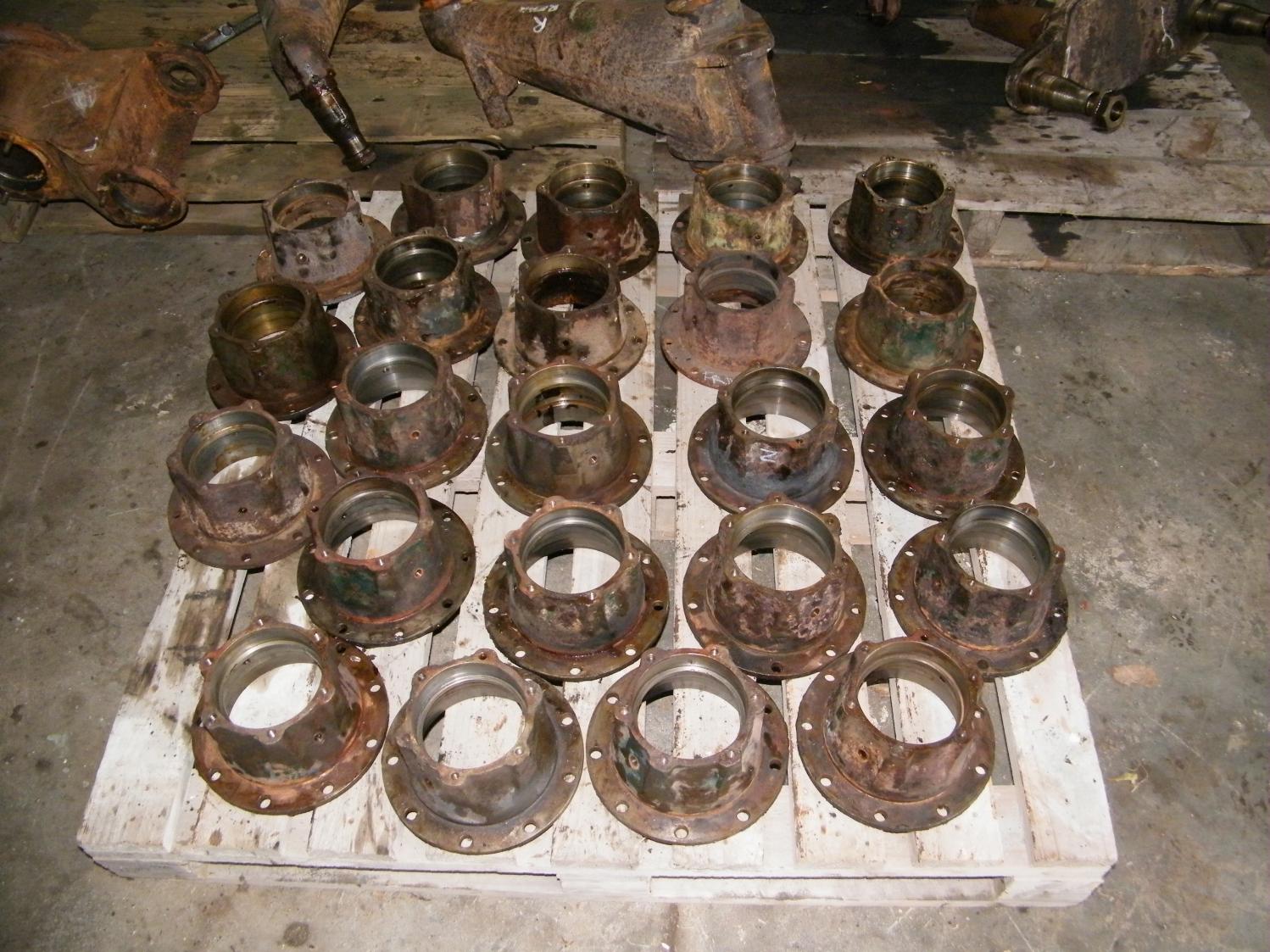
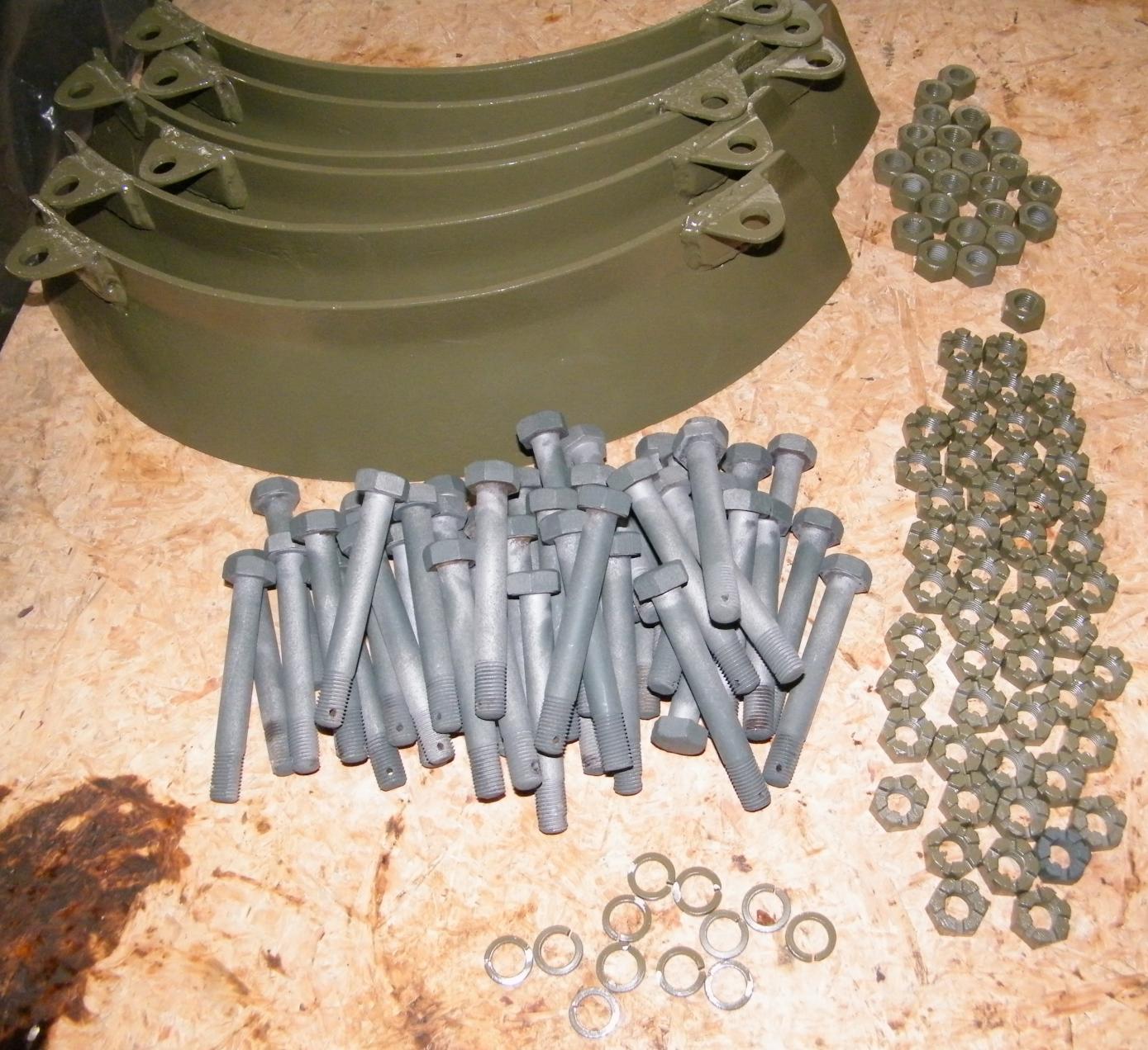
Pictures show the pile of rims / hubs and medium size tyres ready for blasting and painting. There are 8 medium size wheels , with hubs, 16 x rims and 96 bolts and washers and nuts. The larger diameter wheels of which there are 6, and their associated rims and hubs, and 72 bolts! Cheers from The Tank Factory.


-
Are these the type where they are in a boxed unit with 3 "snail drum" air intakes on the out side of what I presume is an oil bath air cleaner, and I guess there is one complete unit for each side of the Tank , that sits on the outside of the mudguards?? Does somebody know their proper name, ie. volkes, etc? or who made them, Cheers Andrew.
-
Todays exercise we pushed the tyres and rims off quite a few wheels. We are using a very handy 175 ton press mounted on the back end of a truck. We had already removed the 12 x 7/16" bolts that go all the way through the rims and hub. Some of the tougher ones were needing up to 40 tons of pressure, but this is only due to rust and old age. When everything is new, you can split the rims in the field with 4 bolts x 3/8" x 2" BSF long fully threaded, and these screw into threaded holes and push the rim from the face of the hub, and then you just bang the other side out. The rims have a slight taper so once started they do get easier to prise off. Cheers from The Tank Factory.


-
Hi Alastair , We have a reasonable selection of tyres , so we will see what eventuates. We do not have to manufacture tyres at this point in time.
Cheers Andrew.
-
This week , the story continues on the shock absorber parts. The first 2 pic's show the new piston rods that I have spent the last couple of days making. The technical side of it , ones end takes a 3/4" BSF castle nut , this eventually bolts to the tube housing on the shock, the other end is 1" BSF, and the piston that travels inside the cylinder goes at this end. Inside the 1" hard chrome shaft is a stepped hole that takes the oil bypass valve and spring, and then an end plug is screwed in when all assembled. This thread is 5/8" x 20 TPI NF. The length of the total rod is 486mm. I am just awaiting the seal packs for the end of the cylinder and we can start assembling them soon. The main tubes are still brewing up in the Molassis at the moment, to get rid of any corrosion. The next 3 pics are of the wheel hub flange assembly, these were all stripped/blasted and painted and new seals installed. These seals run on the dust excluder tin cover that are in behind the wheels. These surfaces will be polished up and refurbed as well. This week has also seen a large number of wheels having all their bolts removed for getting ready to push the hubs apart, hopefully next week I can report on how my jigs and pressing tools have worked! Cheers from The Tank Factory.


-
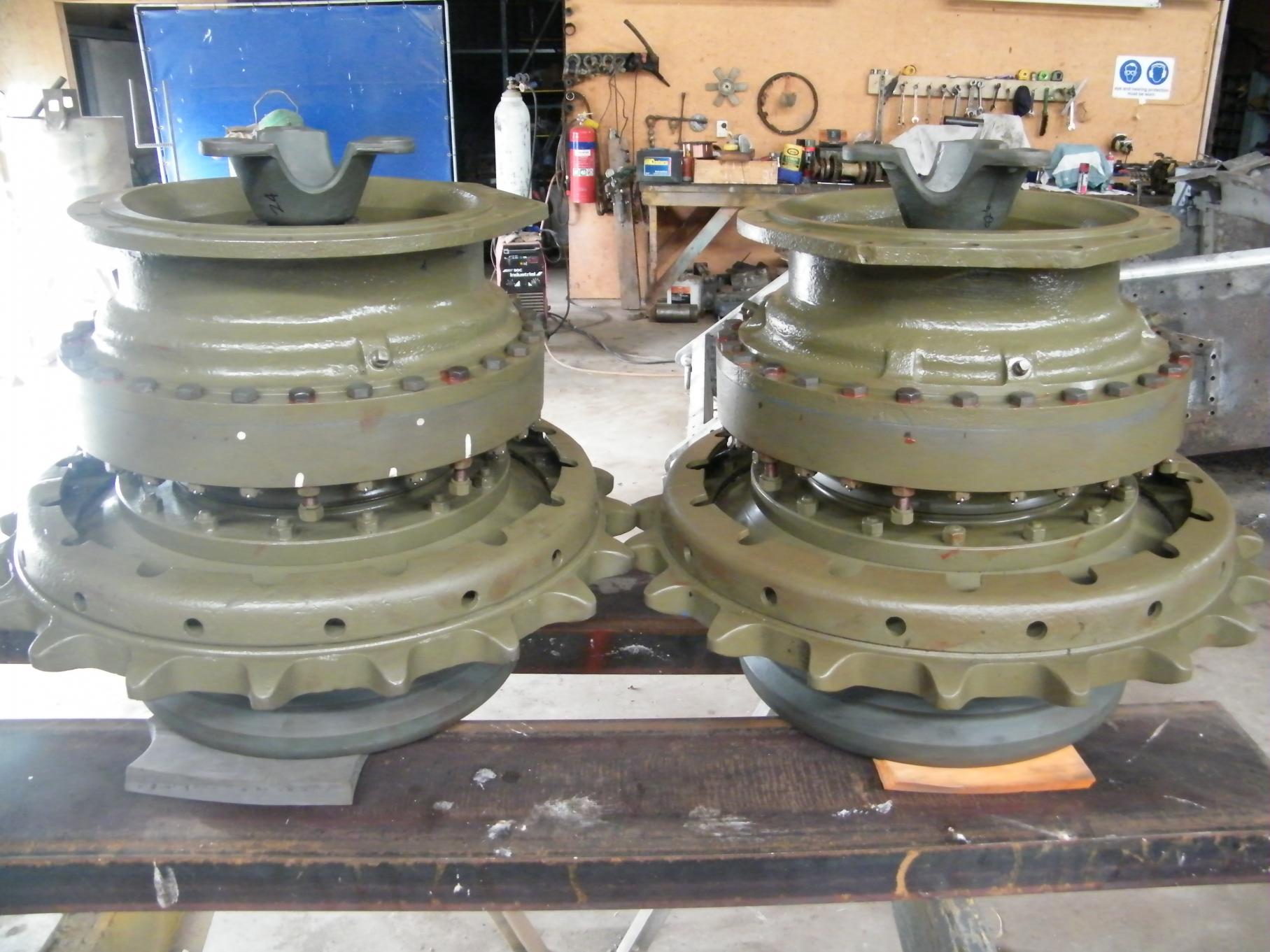
The following pictures show a nearly complete layout of the components that go into making the suspension station, which there are 4 per Tank, 2 x left hand and 2 x right hand units. Missing from the pic is a couple of dust covers for the double bogie unit and the main shock absorber shaft that are getting worked on at the moment. All units now painted in DBG Flat.
The road wheels are to be worked on in the next week or two. I am currently making the tooling for pressing the tyres off the rims, as there are a few to do, and we have a specialist forklift guy that has about a 200 ton ram mounted on the back of his truck. He just backs into the workshop and splits the rims apart, " hopefully " without too much trouble . We use him for doing our M3 Stuart tank wheels, but these are more simple in construction , where as the Valentine wheels you have to undo about a dozen or so 7/16" bolts, and once apart you will end up with 2 x rims , the inner hub , and the rubber tyre wheel that is vulcanized to it's steel rim band. Cheers from The Tank Factory.


-
Here are some pictures of the rain hood. You were making some of these a while ago for the Cromwell? A clever guy like Adrian would also
 probably be able to make these?, could do with a dozen! Cheers Andrew


-
Excellent work Rick, the page on the handles, can you post that again as a separate page, to show all of them clearly
Thanks Andrew.
-
Hi guys, I knew I would get picked up on this! When I wrote it I was going by memory. I stand corrected.
The Valentine uses a Newton VT.II shock absorber, this is an upgrade from the VT.I., ( which used M80 ). The VT.II is now " filled and serviced with Fluid, Hydraulic Brake, No.3, other types are filled and serviced with M.80, as before. The change of fluid is made necessary by the fact that natural rubber glands are now fitted to series VT.II" . This is quoted from the Newton Shock Absorbers For "A" Vehicles, service instruction book 1941. Cheers Andrew.
-
After eating plenty of plum duff, it is now time to get the production line started again. Work continues on the disassembly of the hydraulic spring dampners. I have set up a molasses tank to naturally strip any rust and to clean up the inside of the tubes. I still have a couple to go as the rods are corroded and I want to make sure the inside oil jet holes are clear before I pressurize the cylinder to force the seals out. The seals will be replaced with new ones, which hopefully should be able to be worked out as the inner piston rod is standard 1" hard chrome shaft, but I still have to size the inner diameter of the main tube, so as to obtain the correct rubber seals. The seals were originally natural rubber, which uses mineral oil as the liquid in the cylinder. As we have a few cylinders to choose from , we may only have to replace a couple of the inner piston rods, due to the corrosion. Later this week I will update the suspensions, as these have all now been blasted and painted. Also checked the other day and the Crankshaft has all been ground to .010" on mains and big ends, and has been fitted to block.
We are currently waiting on piston gudeon pins to turn up from the States, as when the piston boxes were opened, these were missing, as well as a few shims to deck the liners to the proper height, a new complete water pump also turned up recently as well , so work still continues in this area. Cheers from The Tank Factory.


-
A few more pieces to the puzzle have been completed. The Turret electric hand controller, and the Turret electric rotation motor have all been refurbished. They are set up on the test control board, to make sure these will work properly before installation. Also we are disassembling the shock absorbers for refurbishing. There are 4 per Tank, one incorporated in each suspension unit assembly. Most of these are usually seized because mud and water have got into the lower tube housing, through the drain hole and have corroded the piston rod near the seals. They are very tricky to disassemble as every part has a spring retaining clip or are pegged with a grub screw. I had to make a hydraulic adapter plug, so we could hydraulically force the seals out the end so that we could get access to the piston end stop, which is 4" inside the tube. Once this end stop is removed the whole rod and piston will come out of the tube. Cheers form The Tank Factory.


-
Also , in a separate bay in the wkshop, work has commenced on the Turret electricals. The Turret electric rotation motor has been stripped and new bearings fitted, also the hand controller for operating the Turret left and right is being looked into. Cheers from The Tank Factory.


-
Today we bolted the Turret ring in place. It rotates very smooth, with no tight spots. It is held to the ring by 30 x 3/4" BSF bolts that are hex head with counter sunk head as well. There are 26 horizontal and 4 vertical underneath where the gun cradle goes. These 4 have their heads machined down so as to not interfere with any gun cradle movements. We also fitted the refurbished Revolver Port holes as well, all nicely greased up for action. Cheers from The Tank Factory.


-
Great Project, sounds a bit like a my Dingo Scout car but scaled up!. Don't want to hijack this great thread, but here is one over this side of the ditch needing attention, Cheers Andrew.

-
The Bush material that is used is Nyloil, which is an oil impregnated plastic. This material is designed for such applications, and we also use it in stone crushing plants , etc. The first pic shows the Nyloil in basic form next to the needle roller bearing that it is going to replace, and then next to those is the original fibre bush that was made back then to replace the needle roller. The action of the suspension unit in this area is only one of rocking up and down, and very limited in that movement.
Next couple of pics show a crude little jig I made to hold the port windows of the Turret , to push the pins out, that were stuck in there, through sitting. When the pins were polished up, you could push them back in the housing by hand, and they were a really neat fit. Cheers from The Tank Factory.


-
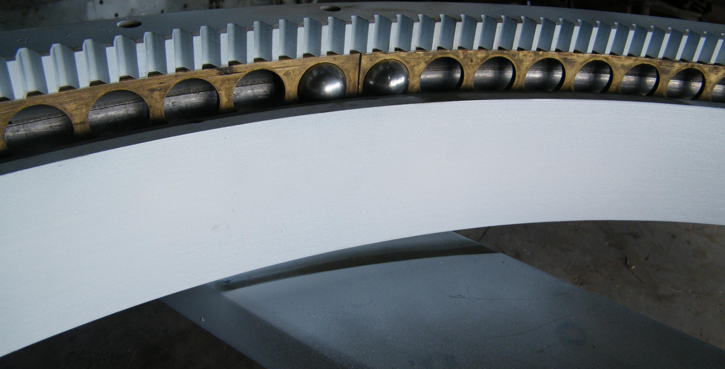
This weeks exercise, we are looking at the Turret ring. After the disassembly and the 3 main pieces have been blasted and painted, the assembly begins. The main ring part that bolts to the Turret is set up , upside down so the 1&1/8" steel balls can be fitted ( 116 in total ). The 2nd piece of the ring , the bit that bolts to the Tank is held just above this main ring part. The four bronze separator spacers are installed and then the balls are fitted into the holes, and then lowered to it's final resting place. Once all balls are fitted the 3rd part, the lock ring is installed and bolted down with 50 x 3/8" BSF bolts. At this stage the four sets of angles that hold the Turret basket can be positioned as well, because out of the 50 bolts that hold the ring down 20 of these go through the angles, and are about an 1/8" of an inch longer in length. Then the Ring can be be turned back up the right way for mating to the Turret . Last picture shows the Turret positioned back over the ring for fitting. Cheers from The Tank Factory.


-
The intentions are to set up the WS19 inside the Turret.
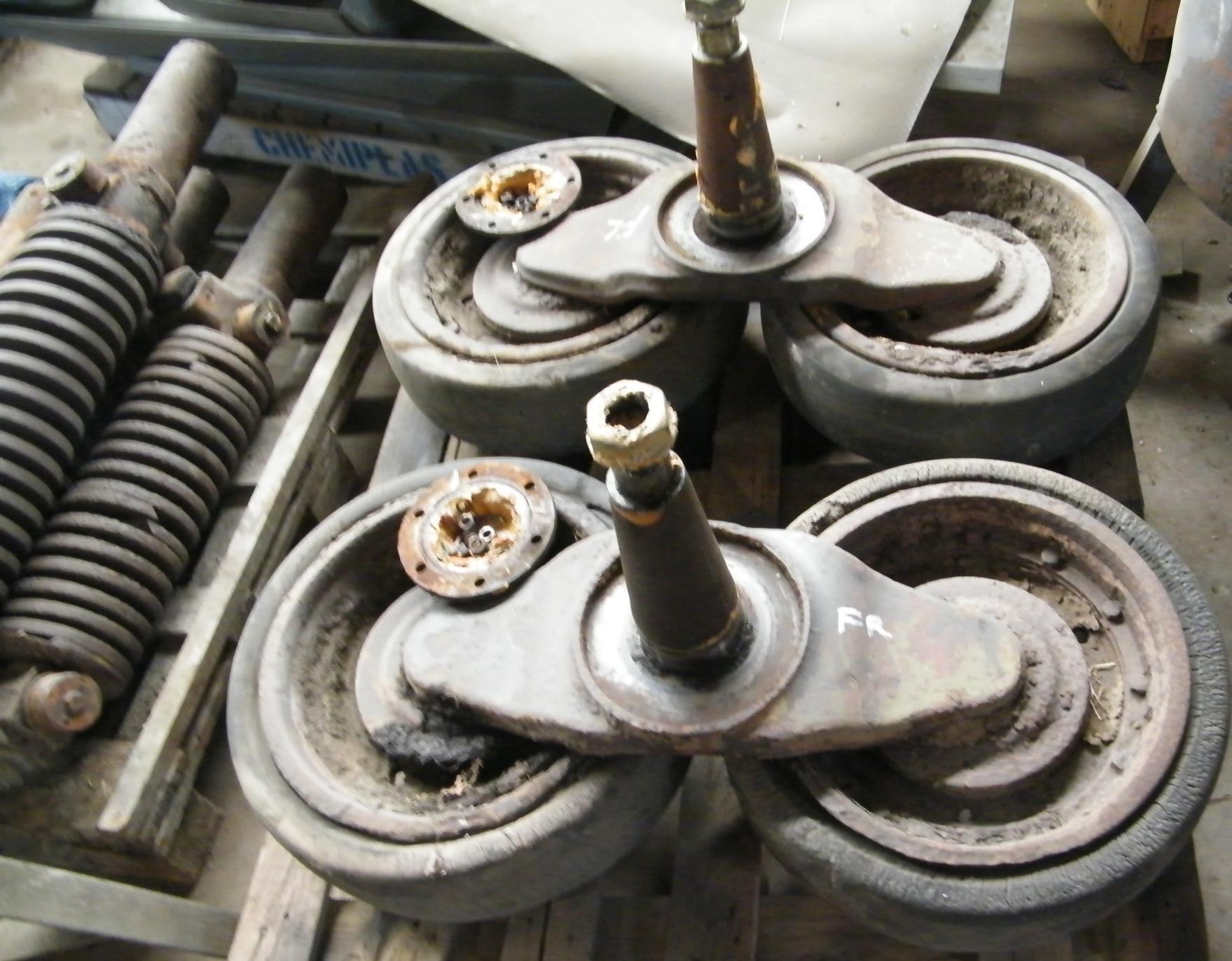
Well this week , stripping out the suspension houses has created piles of bearings, cap plates ,shafts etc. Lots of bits go into a fully working suspension unit!. There are 4 main units on the Tank, 2 x handed for the left side and 2 x for the right hand side. I once saw a war time film where the guys in the factory just craned the whole complete unit, including wheels onto the Tank in one go , did up a few bolts and there it was. We are going to work on the same theory, but may leave the wheels off, for ease of fitting. I will look into this when we get closer to the reassembly line. First pic shows the 4 stations with there secondary motion unit there as well. There is also the double bogie unit casting as well. The Tank has 2 of these per side, so 4 in total. Next are the pile of hubs we can sort through and discard any that look unfit for service. Then there are the piles of inner wheel hub dust/mud excluder shields that take an oil seal, need 12 of the standard size and 2 different ones for the front track adjuster wheel , as well as about 4 different types of bearings that are used. There are also some bushes that superseded 2 different types of needle rollers that were used. I still have to machine these up but have all the material at hand. There are also a bunch of rubber seals that act to stop water entering the hubs that have been water jet cut, so will show the complete layout prior to reassembly when the main units have been through the blasting and painting process. Cheers from The Tank Factory.


-
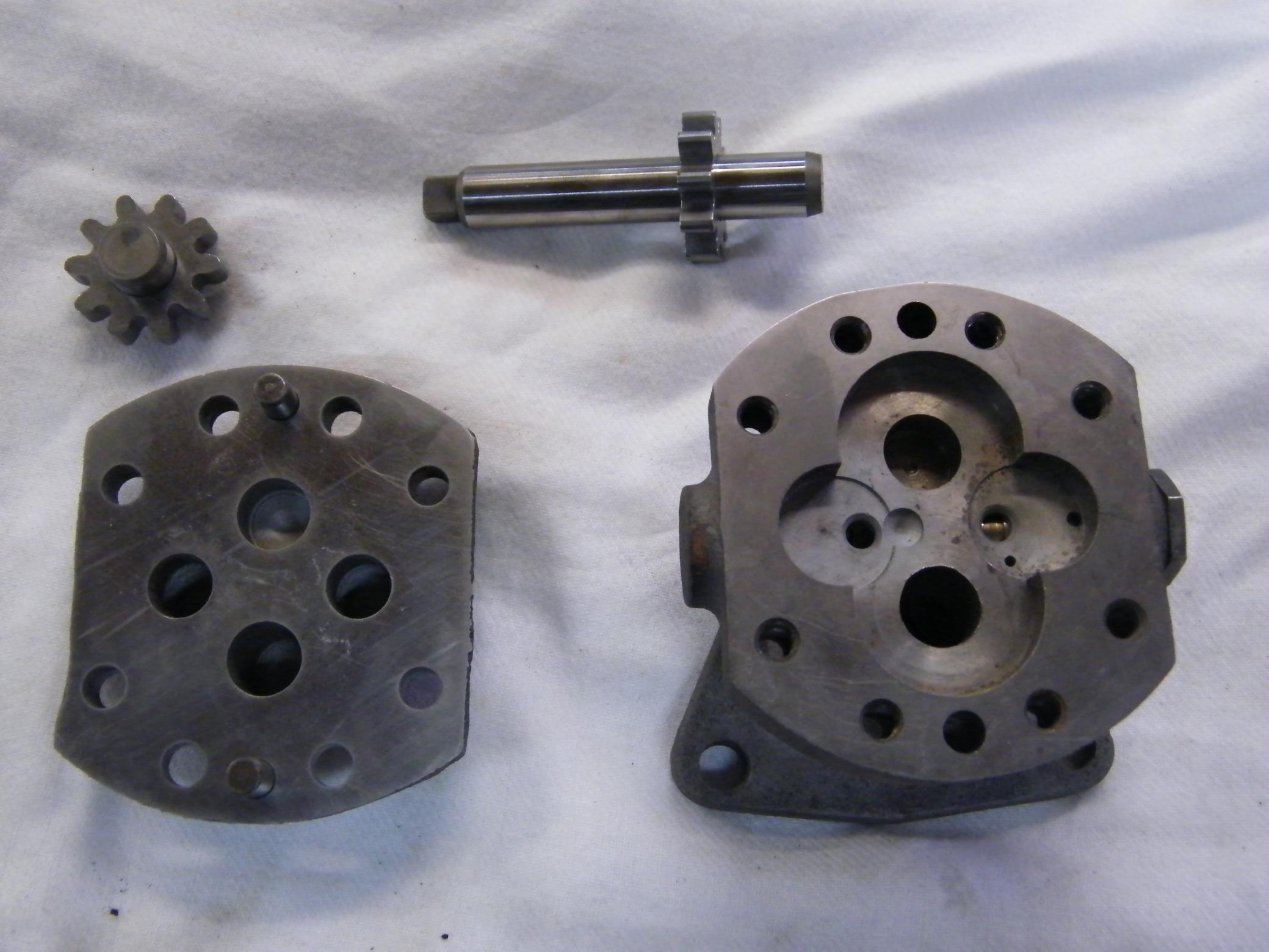
This week we have been catching up on a few of the little component's for the engine. The fuel pump has been stripped and a new kit with new gears are being installed. The 2pdr is now stripped down to just the recoil housing at this stage, with the nose cone and face plate, all blasted and painted and waiting for final top coating of colour. Next I have made up a test bed for the generators and Turret electrical hand controller and the motor that eventually bolts to the Turret Traverse gear. The means of rotating the Turret can be achieved by manually winding the handle or by electrically, when the engine is running.
On the engine side, liners have arrived from the States, grade D, which I believe means pretty much a virgin block, as the fit into the cast engine block is critical, and you can get various width liners to match the hole. The assembly of this should commence this week also.The flywheel is also back from getting faced, just to make sure things run true. We have also started into stripping all suspension down, so this will be updated this coming week. Cheers from The Tank Factory.


-
The Turret internal painting continues as I like to use the 24 -48 hour "window of opportunity " when painting so that each coat of 2k "keys" into the next. The interior of the Tank is to be white. There will be 3-4 coats to get the micron build up, (DFT). The turret ring for the restoration has been dismantled and inspected. The ball race is in excellent condition and all 108 x 1 &1/8" round balls have cleaned up very well, as well. These balls are held in location by the brass separator rings, which consists of four per turret ring unit. The turret ring separate's into 3 major rings , that all form part of the ball race , and when it comes together they make the whole ball race. There is the main ring part that bolts to the underside of the turret, then there is the ring with the teeth, and then there is a smaller "lock ring" .These are held all together by a quantity of 3/8" BSF bolts. Cheers from The Tank Factory.


-
With the ring off the Turret, the rest of the fittings have been stripped out and removed for refurbishing later. This included the commander's cupola, roof vent , and port windows for exciting of spent shell cases during battle, and periscope roof port. Pictures show core unit ready for blasting and primer applied. Cheers from The Tank Factory.


-
Started on the "Business" end of the Valentine the other day. The 3 tonne Turret. Normally this job ends up being later on in the restoration, but......... it was just sitting on it's stand just begging for some work to be done on it. First the 2pdr gets stripped out by removing the pivot pins each side, and a few bolts inside that would stop the withdrawal of the gun and mount back out through the turret. Once it goes back you just lower it to the ground. It comes out complete with nose cone mantle and 60mm thick face shield all bolted together in one piece. Next, stripped off the turret ring by removing all the bolts around its base, the 3/4" impact drive comes in handy here. 1/2 dozen bangs from the sledge hammer and the ring just falls off! This ring is not being used in this restoration, have pulled a far better one from the store for disassembly.
Cheers from The Tank Factory.


-
Thanks guys for the comments,
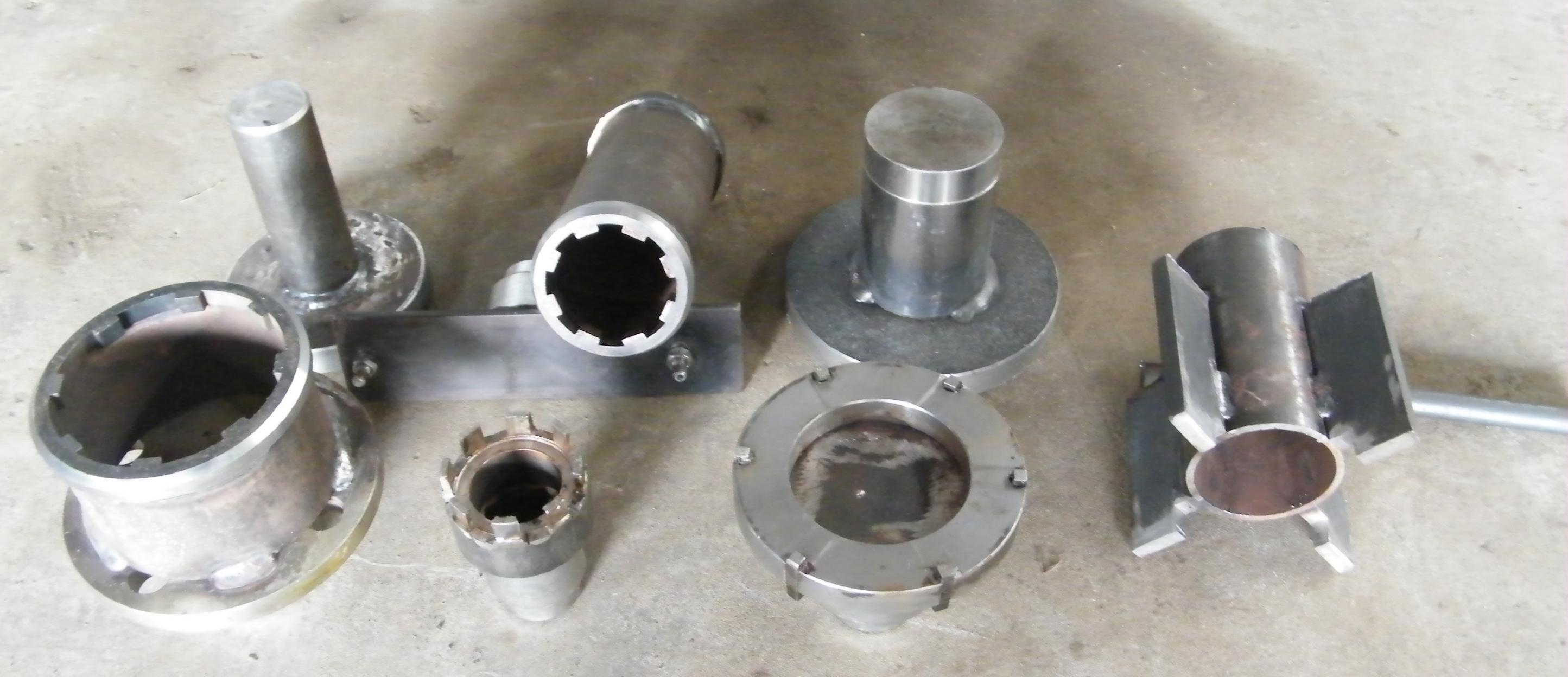
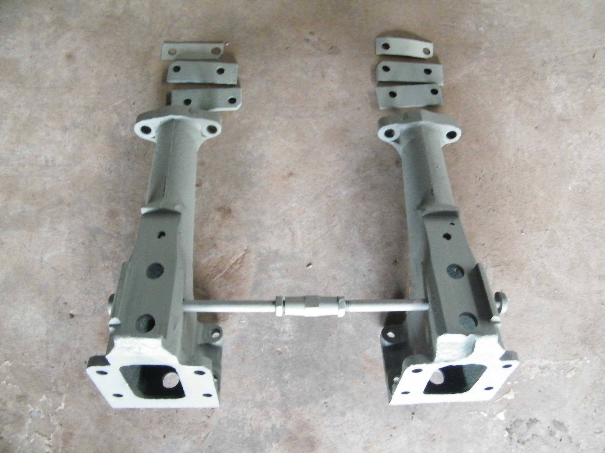
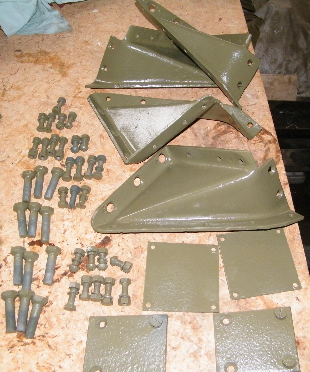
Back on the Valentine this week, the Final Drives are completed and ready for the final paint job, and installation. The second pic shows the tools we have had to make using the water jet cutter, for making the cut outs so they can fit over the special nuts that are inside the final drives and gearbox. Otherwise too much damage is done to these parts if not undone properly. Next pic shows the bevel box supports, which are mounted to the rear of the hull, and shimmed accordingly, something which is a common occurrence on the Valentine, a very British thing!. Next is the front engine support mount, that has been cleaned up as well. Work continues on the interior of the hull , to get ready for the blasting and painting stage of this. The last broken studs have been removed from the hull as well and none have beaten me!, one way or the other they have all come out. Cheers from The Tank Factory.

-
This last weeks exercise has gone through the stages of pulling all remaining suspension units off and tapping holes out and cleaning threads up. We have been waiting on some parts to come through the blasting and painting stages to finish the final drive assemblies, which hopefully will conclude this week, after we get a nice wee "pickin" trip out of the way! First pic up shows final drive wire guards and the bolts that hold the final drive housings' together, about 30 bolts for each side. 2nd pic we have the middle support roller castings, that have the track return rollers on, these being all blasted and cleaned.3rd pic shows the hub components for the return rollers, 6 sets required per Tank. Next there are all the suspension units pulled off awaiting their turn for processing. Pic 6 are of the end access caps that come off the suspension housing "wings" that are attached to the side of the hull and their bolt group. The last two pic's show the hand tapping out the 5/8" BSF threads that hold the wings on the side, as you can see we are really getting down to the kitset stage, but soon the rebirth will start, and the fun part of bolting the subassemblies onto the hull will commence . Cheers from The Tank Factory.


-
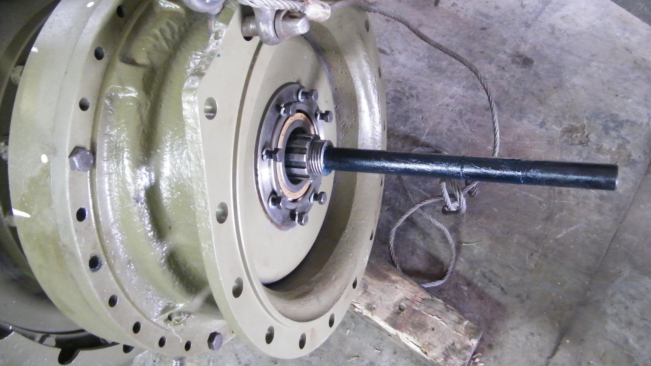
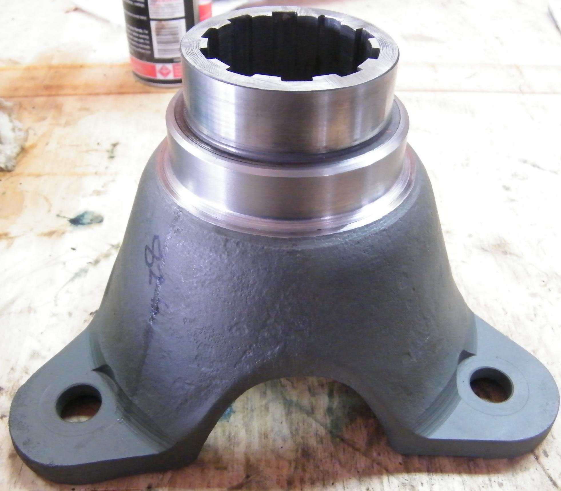
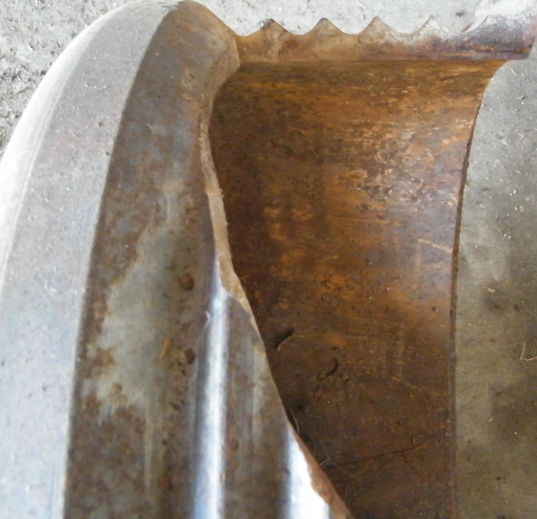
A couple of pics to show brake rod inserted. A spring about 3" long goes down the hole in the middle of the hub unit then followed by this shaft which is marked up as a certain way around that it goes in. On this inner hub will be a steel flange bolted, with another oil seal for there is another inner ball roller bearing in this housing. Second pic shows the drive flange that slides on the splined shaft from the final drive, seal surfaces excellent. Third pic shows a sectional view of the drum casting to give you an idea of the cross section for cooling. Cheers from The Tank Factory.


restoration of a valentine MK5 tank started
in Tracked vehicles
Posted
The Ordinance department has finished the primary restoration of the 2pdr gun, once fitted into the Turret, it will receive the rest of the equipment to be bolted around and underneath the gun. Cheers from The Tank Factory.