


simon king
-
Posts
642 -
Joined
-
Last visited
-
Days Won
3
Content Type
Profiles
Forums
Gallery
Blogs
Events
Articles
Store
Downloads
Posts posted by simon king
-
-
Surely as a representative example of the wartime production efforts by AC Cars, the trailer chassis could be restored, as is, to ex-factory condition by the Owners Club. If the tanks were manufactured by a third party, it’s restoration in its current state is a legitimate exercise.
The missing tank will inevitably turn up eventually. Admittedly the pump and filter gear are more of an issue but it wouldn’t be the first time such items have been reproduced.
-
I am now looking to complete the truck/ground WS19 installation in my MWR. The B set antenna mount and associated leads are sorted but with regard to the A set antenna, all I have is the acorn shape rubber antenna mount. I have tried a trial installation on the MWR roof, but I think I need more parts
in order …
Rubber antenna mount
Mounting base, Antenna No 3
Plates, connector No 2
WS19 Antenna Feeder Assembly No 9 (plugs into the antenna fitting on the variometer mount/antenna base which bolts to side of PSU)
Is this correct and can anyone point me to any possible sources for the parts I might need.
thanks
-
AES (Auto Electric Supplies) in Tenbury Wells, Worcs is your saviour
small bayonet cap, dual contact, small or medium globe
BA15D is the right one I seem to recall, but double check
Available in 5 or 10 watt and 6v or 12v
-
That’s how I did my 10cwt GS as well, one circuit all the way round from the British trailer socket and back to it. The switch between axle floodlight and tail-light has sufficient terminals to permit this.
-
If the roof is canvas covered then there is an example of how to do it in the thread on the restoration of the RAF Leyland workshop truck on the WW1 forum here on HMVF.
Seems to use a specifically purposed product called “Williamson’s Canvas Roof Bonding Compound”
-
The two tilt frames are now ready for paint. The front one just needed a bit of judicious jumping up and down on it to straighten but the back one needed more work. Sprung welds and extraneous holes in the frames have been repaired and a new central stanchion at the front has been added.
More significantly, the lengthened front and rear tilt frames used on the MWR had been chopped off. To restore these, tube of the correct diameter was obtained and spigots were turned to fit in the tube ends. These could be secured by the cross bolts used to secure the frames into the body-side sockets. The join is hidden by the socket, so the frame appears as a single piece.


-
 3
3
-
-
I do water slide transfer lettering for that CAV switchboard unit - if you’re interested pm me.
Oops just noted it’s a later one with the moulded lettering anyway.

-
1
-
-
Small update.
In the MWR the tilt frame elements are welded together for strength and stability, so need to be removed as a single item. 80 years of use and abuse have resulted in some slight distortion to the tilt frame, which means that it cannot be removed without significant effort. The distortion cannot be seen when the canvas is on.
The pragmatic solution is to paint strip in situ, so that’s what I’ve done. One weld on the frame has popped and the front stanchion needs to be replaced as it had fractured at the weld.
Just the fiddly bit of paint stripping inside the inverted pyramid variometer mount still to be done.
Finally, there is the easier job of stripping the 4 rifle spring clips attached to the tilt frame and adding some new leather padding, which is on the way.

-
4
-
-
Strewth , it’s a year since my last post and looking at the pictures above, I’m not entirely impressed with what I’ve actually achieved in the last year….oh well
The tanks and trays have been removed, stripped, repaired and primed as necessary. That means all the fittings under the floor has now been removed, repaired (or replaced) and primed as appropriate.
Finished the strengthening boards attached to the tilt last week so onto stripping the front and rear tilt frames. The metal cappings for the rear of the planks were a bit of a nightmare as they were too narrow for the folding machine.
Looks as if the front frame is slightly bent, so some gentle persuasion will be needed. On the back frame, I need to add a new tubular bar from front of tilt frame to the front wood board and then add some length to the front and rear tilt frames to replicate the MWR fit. These will just slot into the existing tubes and be secured with the existing socket bolts as I’m not messing around removing the tilt frame. It had to be jacked up to insert the socket bolts.
In the MWR all the tilt frame elements are bolted/welded together so it has to be removed as a single unit. This brought problems with the planks in the front n/s corner behind the charging board/control box covers as there was no room. Had to reduce the width of the planks in that area and create a corner plate with captive nuts to take stove bolts rather than the carriage bolts used everywhere else. Won’t be seen as under the canvas though.


-
5
-
-
I own one of the jeeps used in the film. Found the Rangers film marking on the windscreen apron under a coat of paint. “Extremely well used” was a kind description of its condition when bought about 40 years ago.
It was also used in an episode of The New Avengers

-
Thanks for that. Does the databook specify tyre size by any chance?
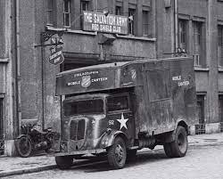
I think some of the canteens have twin rear wheels whilst others seem to have singles. The canteens also appear to have both the prewar stamped radiator grille and the later “utility” shape.
-
Thanks for that.
There are comments to the effect that 7V tippers were used by both the RAF and Royal Engineers but I can find no reference to them in the Army’s Databook of Wheeled Vehicles -
Does anybody know the wheelbase of the Fordson 7V chassis/cab used for the NAAFI and Salvation Army tea wagons/mobile canteens?
Thanks
-
Anybody got any pictures of Mk II DACs in British service fitted with two headlights in the front locker? The Mk II DAC at Bovington has this modification, as do the DACs used by the New Zealand Army.
I just wondered how common this modification was as there don’t seem to be many photos around.
thanks
-
7 hours ago, radiomike7 said:
Also used for Upkeep. Contrary to common belief the 8000lb and 12000lb Cookies were a larger diameter than the 4000lb and not just 4000lb units bolted together as can be seen in this photo.

Presumably these trolleys belonged to 617 Squadron who used the KC Squadron code in the later part of the war
-
1
-
-
Interesting view of the two rear lights in that picture of the spring assembly as well
-
Given your MW is fitted with a non-original OY cab, I would be inclined to leave well alone. If it works, don’t fix it.
-
I think that is the position for the screened coil used in the MWR FFW
-
The correct carb is a Solex type 35RZFAIPO/C581/0. C581 should be stamped on the carb. That is the 35RZFAIPO specific to the MW, as it was also fitted to other Bedford’s such as the QL
-
1
-
-
Can even be seen (or more accurately, not seen) on the brass manufacturers plates attached to some of the tanks in the Tank Museum which have also had the manufacturers name ground off
-
1
-
-
Not party to such detailed information I’m afraid.
The build photos of the test shots for the MkI are now on line, so things are definitely moving forward. All the other elements (markings, boxart etc) are already in place
-
Kevin,
FFN for 2FFY is 18000
-
There are no RA units with the 5 digit FFNs you quote in the list I have, and the presentation is way too large as well. FFNs were usually only about 1” lettering above the colour bars, as part of the preparation for overseas movement markings
-
1
-
-
Perhaps too large for a Field Force Number (which can be up to 5 numbers) above coloured bars which would be used for mobilisation purposes. More likely to be a unit serial applied on a coloured (?red/blue) arm of service square. Is all the number readable?
If it is (possibly) 74 on a red/blue square, that would indicate a Royal Artillery Field Regiment in an Armoured Division from 1944. Is there any further Divisional marking on the other side of the cab?
-
1
-


No 19 Set Ground/truck
in British Radio Equipment
Posted
Thanks for that, it’s on the roof and won’t be seen, so decided to have a spacer laser cut out of 5mm plate, together with an example out of 2mm plate which I will use to reproduce a connector plate. Will replace them as I find originals.