


landrover nick
-
Posts
179 -
Joined
-
Last visited
-
Days Won
2
Content Type
Profiles
Forums
Gallery
Blogs
Events
Articles
Store
Downloads
Posts posted by landrover nick
-
-
PART SEVEN
The warmer weather is beginning to arrive and the Bedford came out of winter hibernation this weekend
photos one and two are the truck coming out of the machine mart tent were it has spent the winter
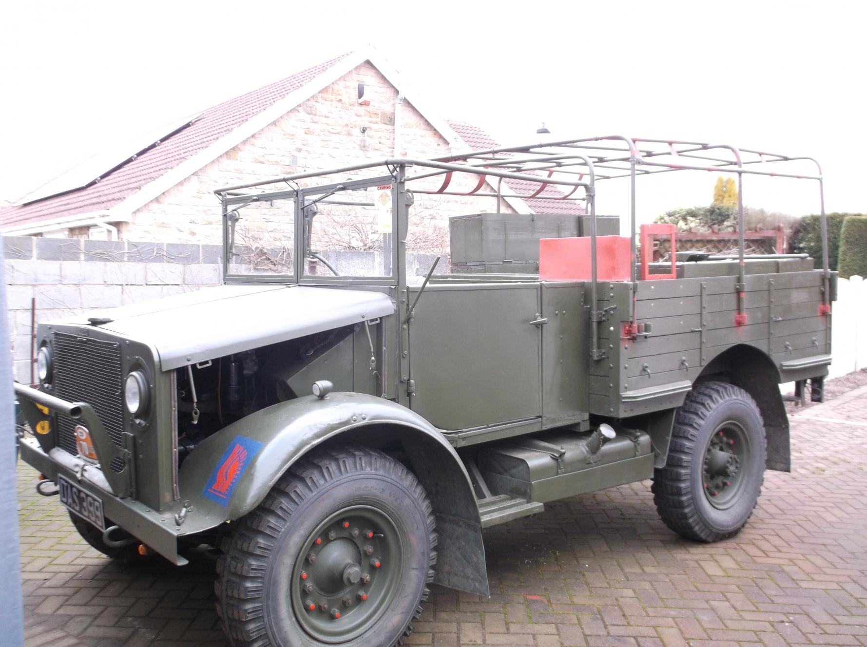

photo number three is my newly restored air cleaner it took a very long time time to find the missing air cleaner and the only one i could find was in Scotland and after stripping and shot blasting looked as though it had spent a long time full of water it was repaired by using the oil pan from the bottom of a landrover air cleaner which was exactly the correct size

photo number four shows the rear body and hood frame after a fresh coat of British olive drab now this is done i can start assembling the rear body interior

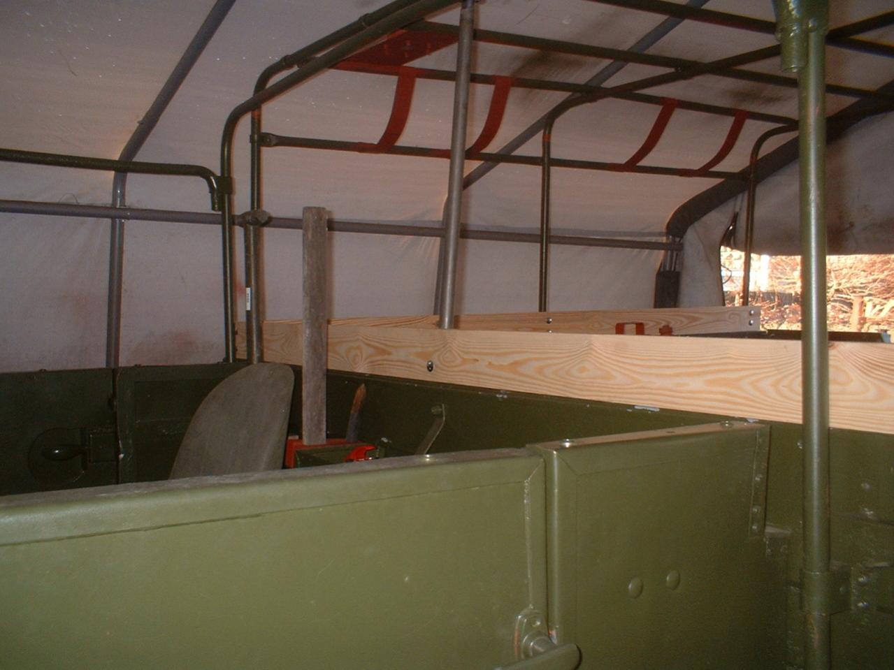
photo number five shows the final pre-assembly work on the rear control box mounting the ammeter and the covers for the control box and the no 5 generator control panel are now all finished and need to be fitted before the extra body planks as the back edge of the covers is screwed to the top edge of the GS body i think that this may be to give the electrical items some better weather protection

I mentioned in an earlier post i had been working on the Z number registrations and contract numbers the observant amongst you will have noticed that the number on my truck is not an MWR Z number it is in fact a modified phone number i made up for Normandy last year .
Bart Vanderveens kaleidoscope of bedford & vauxhall military vehicles lists MWR total production as 5,500 trucks under 4 contracts ,having managed to get a copy of Rob Van Meel allocation of b vehicle wd numbers and cross referencing both i have the following
contract number , number built , description znumber
294/v/m5275 974 units truck 15 cwt 4x2 adapt for conversion to wireless Z4908541-Z4909515
294/v/m5058 829 units truck 15 cwt 4x2 adapt for conversion to wireless Z4909516-Z4910345
294/v/4714 1699 units truck 15 cwt 4x2 g/s adapted for wireless Z4903700-Z4905399
294/23/s3053 1999 units truck 15 cwt 4x2 wireless Z5252268-Z5254267
B8834 7 units truck 15 cwt 4x2 wireless Z4577022-Z4577029
N/K 6 units truck 15cwt 4x2 wireless Z4577030-Z4577036
TOTAL 5514 UNITS
i think the last two on the list could be pre production batches looking at the low Z number
MWR production is said to have started in 1942 the chassis number on my truck is 1942 i need to know how many MW were built per month i can then work out what month my truck was built in and the correct number will be some ware in the batch Z4908541-Z4909515 just have to work out which one to use are there any other MWR owners in this batch that i compare details with ?
Nicky
-
Time for an up date
part six


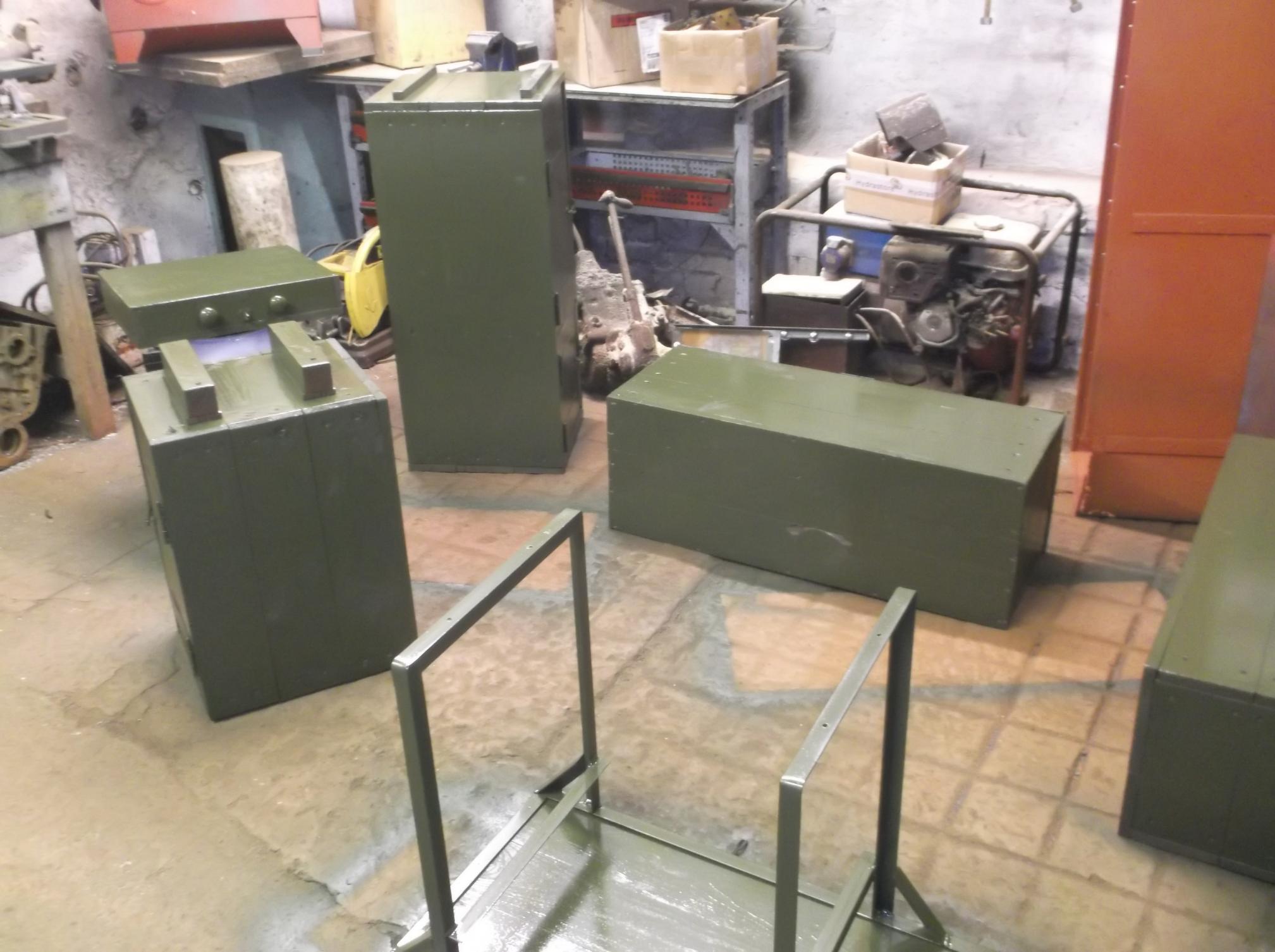
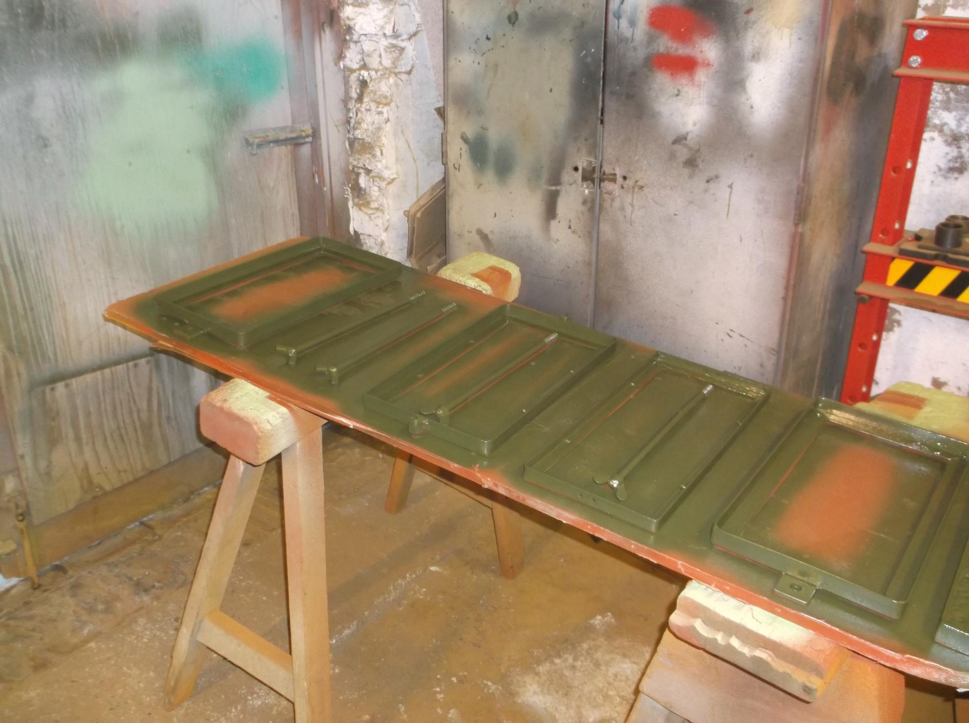


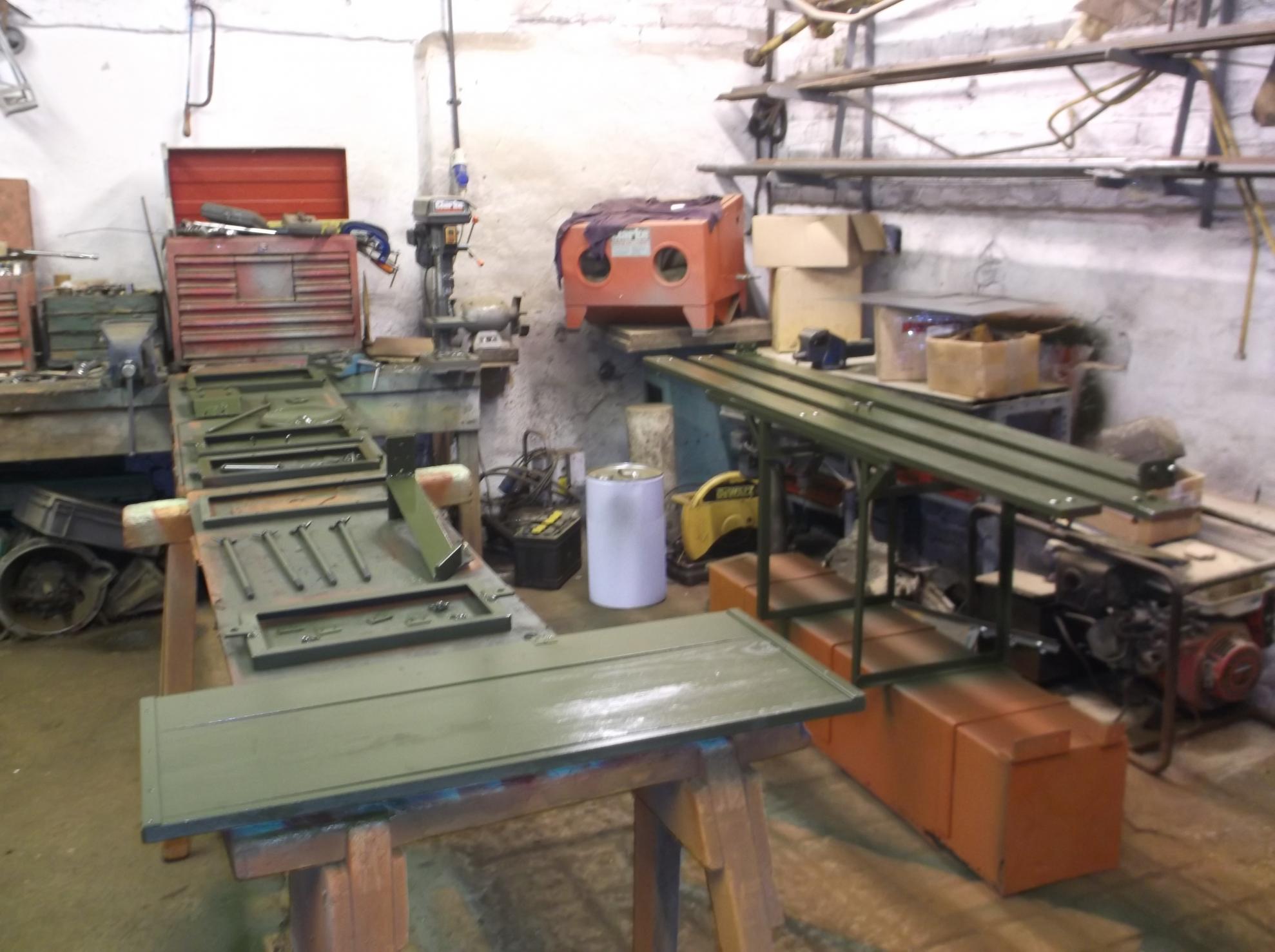
The last couple of weeks have seen some slow progress ,trying to paint in this winter weather is hard work and very time consuming the red oxide paint being the worst needing a week to dry fully i think this because it is an oil based paint as you can see all the lockers ,battery clamps ,radio table and extra planks for the top of the body have now been painted in a base coat of red oxide and top coat of British olive drab the interior of lockers has been painted in eau de nil as planned , it looks better in the photo than i actually is but is making the inside of the lockers much brighter ,looking forward to some warmer weather so the truck can be run out of its tent and i repaint the inside of the body ready to start the final assembly

-
would these be markings , yes i use tony for all my stencils ,how do they conform to usual arm of service and unit layout my truck at the moment has a royal signals arm of service marking and 24th independent guards unit marking

thanks for you help
Nicky
-
Hi all so we are not going to be on our own then, couple of things i need some help with ,thought maybe it would be good idea to have some temporary vehicle markings made up for the parades and whilst on the island ,what would the vehicle markings for force 135 have been .Jules any chance of an update on your OGEL application i had a quick look on the recommended web site what a mine field i think i am going to need some help to get this right
Nicky
-
these are the photos to go with part five i think they must have timed out whilst i was doing the post sorry

Nicky

-
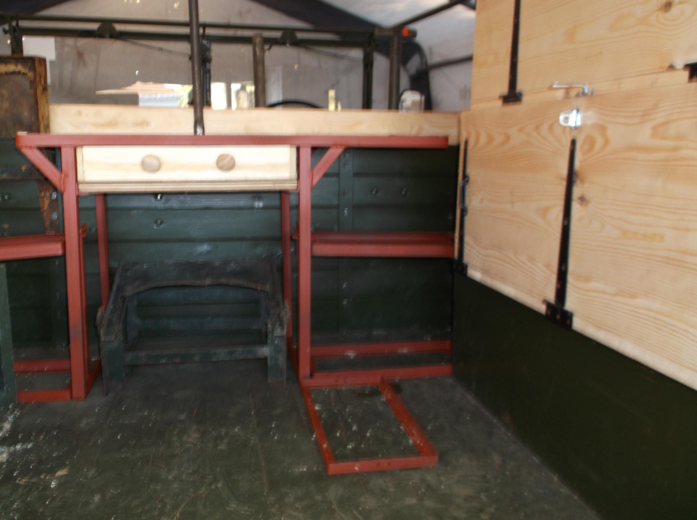
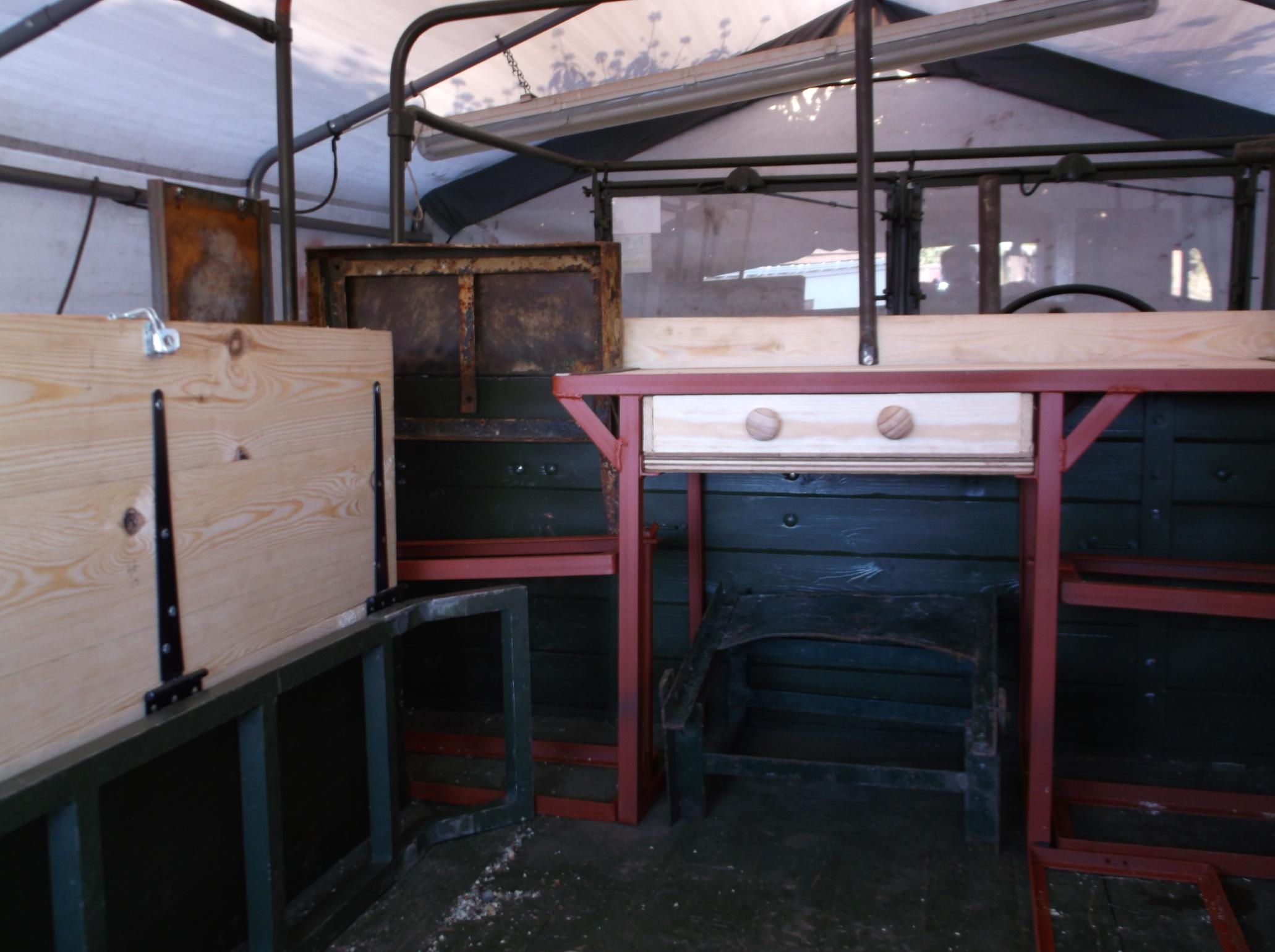
PART FIVE
making steady progress ,all boxes now made ,the drawings seam to work fine with only slight modifications needed to make the drawings work correctly for manufacture ,photos show test fitting of table ,battery clamps, mounting for no 5 switch board ,control box and newly copied wireless operator seats
[ATTACH=CONFIG]100622[/ATTACH][ATTACH=CONFIG]100630[/ATTACH][ATTACH=CONFIG]100629[/ATTACH][ATTACH=CONFIG]100628[/ATTACH][ATTACH=CONFIG]100627[/ATTACH][ATTACH=CONFIG]100626[/ATTACH][ATTACH=CONFIG]100625[/ATTACH][ATTACH=CONFIG]100624[/ATTACH][ATTACH=CONFIG]100623[/ATTACH][ATTACH=CONFIG]100631[/ATTACH]
all have now been removed the no 5 switch panel needs shot blasting and then i can start painting the inside of the boxes will be BS216 eau de nil and the out side and every thing else will be British olive drab
more soon
Nicky
-
No progress here either got the correct short wheel brace from Chris Morter but it will not fit in the clips in away that looks correct my January 1945 hand book still shows the adapter in use for the split rim nuts

Nicky
-
Tom what information do you need

Nicky
-
Hello got my confirmation today that we are booked on to the 2015 liberation tour to Guernsey in May we are taking the Bedford MWR anybody else going from on here
Nicky
-
Hi Sean
yes your correct just checked on the factory interior photos they are the other way round will fit the correct way on final assembly
Nicky
-
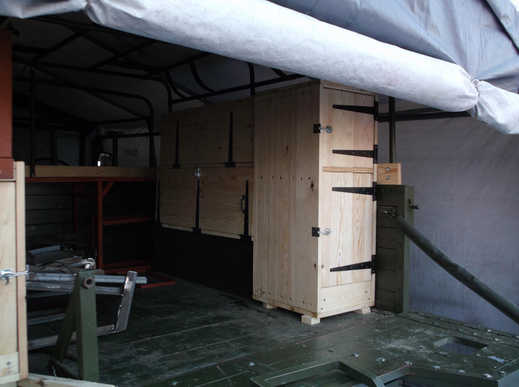
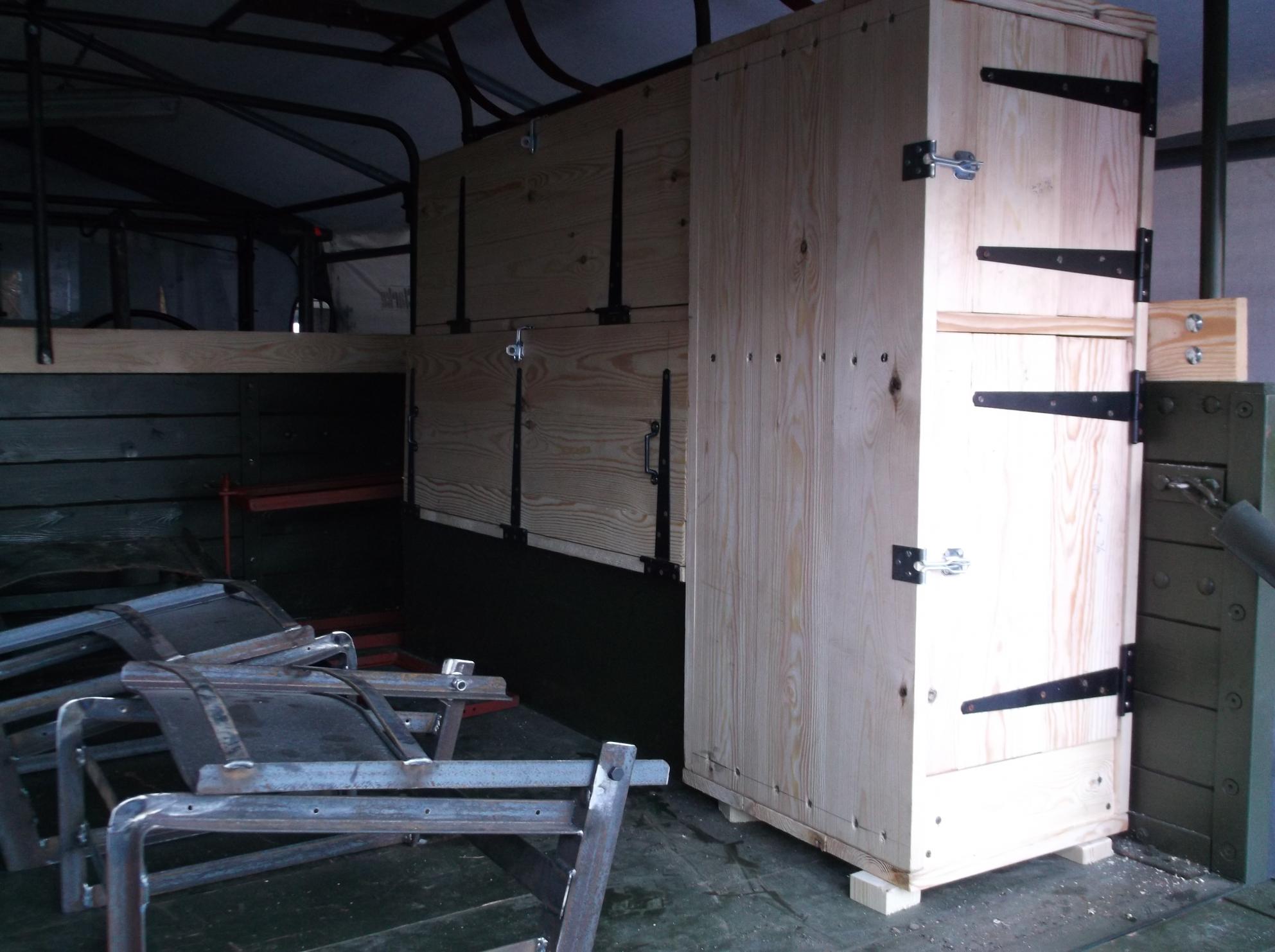
part four
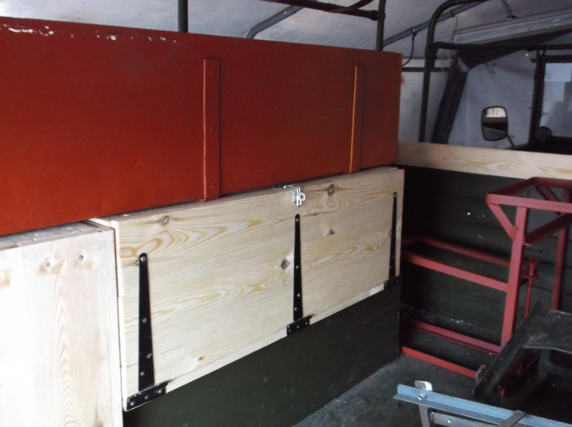
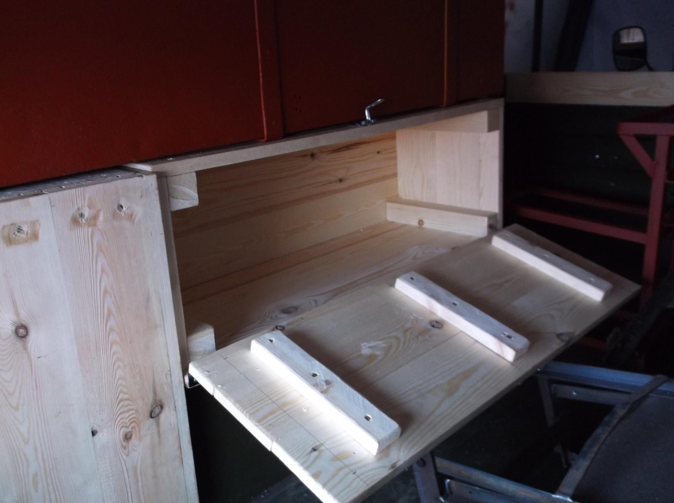
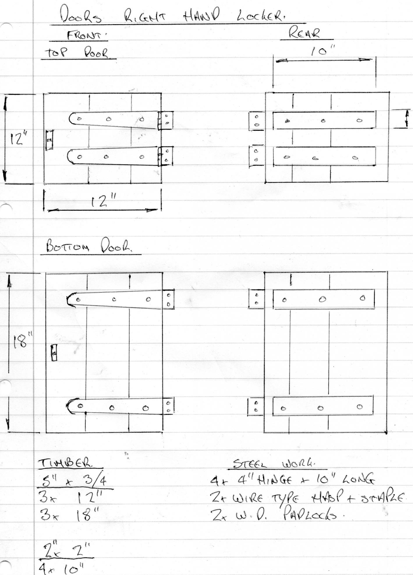
I have been working on the layout and drawings to make the wooden lockers to kit out the rear of the truck as i have only found one of the big steel boxes (i think they would be used to store the radio aerials )so far, i have decided that i am going to fit two spare radio set boxes and a radio spare parts box this layout i am told is correct for a radio intercept equipped truck ,this will also give more space for camping gear and can be changed if i find the missing box the timber has now arrived so i can start to make up the boxes more next week
Nicky


-
part three
The next set of photos show the results of my recent very successful trip to Pete Gains i came away a happy man with these


the first two photos are the rear radio operators seat ,the truck would have had three of these in the rear fitted with very basic canvas seat covers , i can now use this one as a pattern to make another two

The next item i had not expected to find and was in pile of unknown items ,it is the mounting bracket and cover for the no 5 charging panel something i was expecting to have to make.
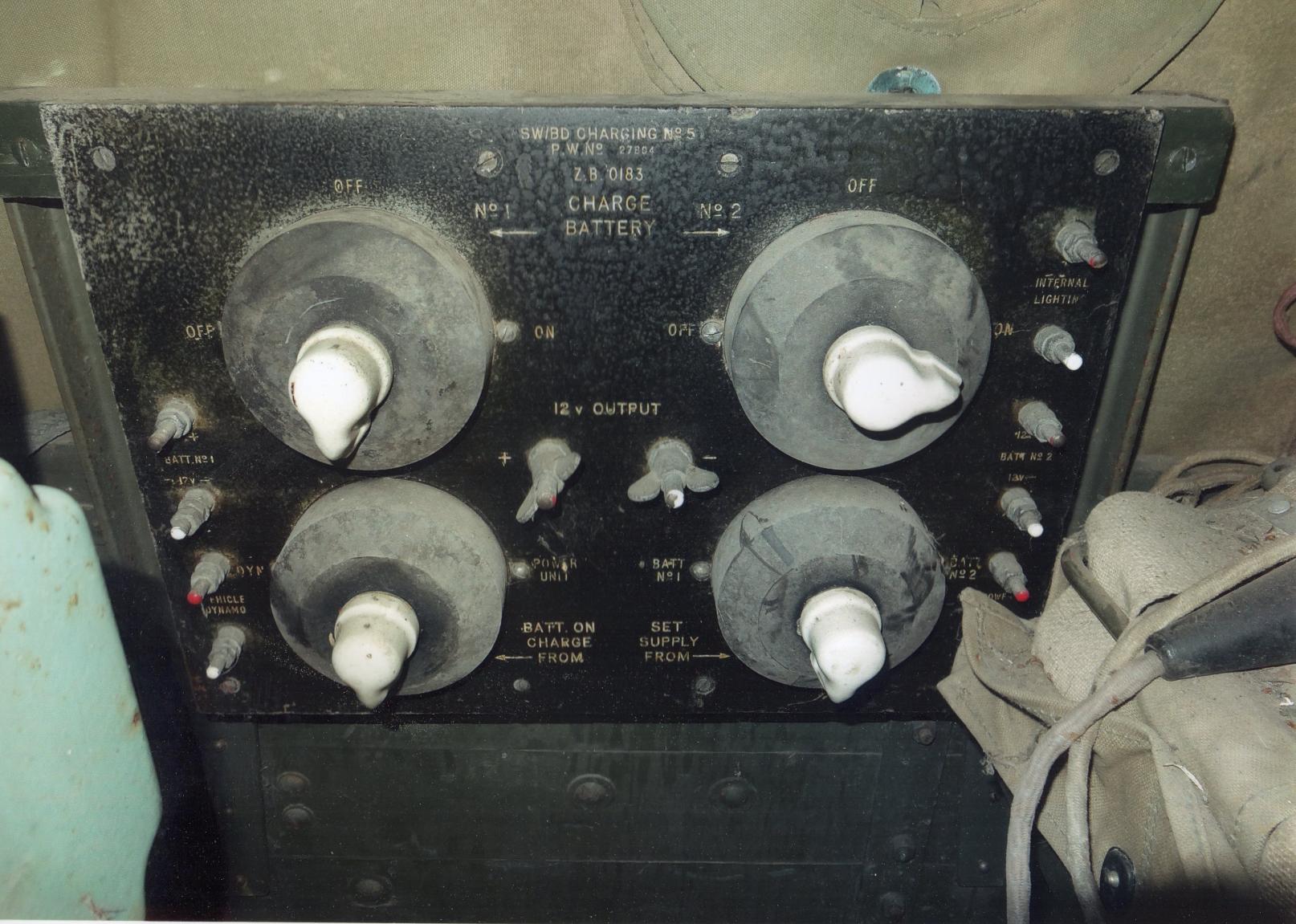
This is the no 5 charging panel i am still looking for this part anybody help with one ?

Another good find was the rear control box this was used to control the charging system for the rear of the truck
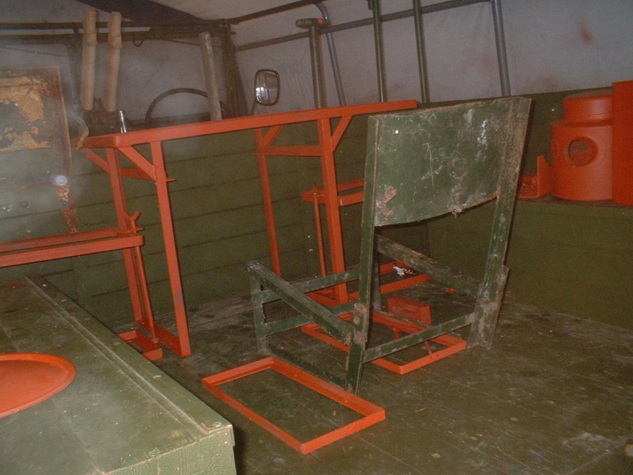
The next photo shows the frame work for the radio operators table and the clamp frames to hold the radio battery's the new battery boxes are being made and should be ready to collect from Stoneleigh

Nicky
-
Tom i have been working on a list of the Z numbers and contract numbers for the MWR have you got any idea of the date of manufacture of of your truck or the contact number it was built under
Nicky
-
Still looking for drawing / photo of wheel brace
Nicky
-
This any better,
Dave is correct Pete Gaine supplied me with the two jack extension bars and handle just couple of weeks ago if you search for Ernlake - Britool jacks there is complete web site dedicated just to the jacks and there handles

Nicky
-
Hi Richard the flax canvas sounds interesting i will ask Steve ,have checked on there web site no photos of your truck do you still have any photos of it ,Steve said he had patterns for some of the items i need i wounder if these were for your truck
nicky
-
Hello Martin
the clips you will find on e bay look under bedford mw and the pick axe and handle and the shovel are all standard general service military items
Nicky
-
PART 2
Before i start to install the new interior i need to add the extra plank which fits on three sides of the existing body planks
 the empty body ready for work to start
 i have seen several posts on this forum saying that the additional planks are used to stop things from sliding off the wireless operators desk but the real purpose of the planks is much more important they are used to lock together all the tilt frame hood sticks and help carry the extra stress which is created on the tilt frame by the two radio aerial mountings if the truck was fitted with a no 19 set the A set would have an 8ft or 12ft rod aerial ,the B set a 2ft aerial with the maximum length of aerial 34ft the aerial mountings are welded directly to the tilt frame and an additional central support bar fitted to the front hoop
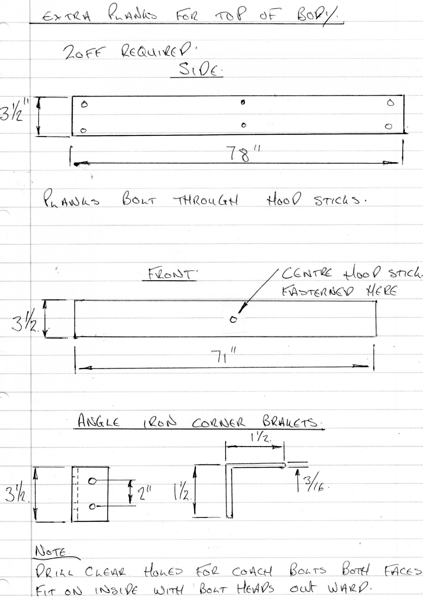
my local timber company supplied all the wood last year when i built the new body and they have supplied all the timber again in scotch pine a few hours work soon had the parts assembled
 corner bracket
  front hood stick support
the completed support frame the four curved brackets on the side hood sticks are also used to strengthen the tilt frame
Nicky

-
Guess what Rivet the cab tool layout on your aero screen truck is completely different this is the only photo i can find ,( i thought i had more ) it shows the correct tool layout on Rippos truck when we went to look at it .I think he will be only too happy to supply photos for the other tools did you get the photo of the switch panel i emailed you

Nicky
-
Hi Dave contact details for canvas supplier are
Undercover Covers
85 Moseley Street
Digbeth
Birmingham
B12 0RT
Email enquiries@comptons2000.co.uk
Contact number 0121 6225562 ask for Steve

i had a very hard time to find a supplier that was interested in making a rear hood canvas for the MWR but Steve was more than happy to help ,photo shows the MWR in Normandy last year with the rear canvas they made for it ,sorry i have no costs as yet for the cab canvas or the door tops but last year they charged
MWR rear canvas £600.00
Gear stick gator £ 25.00
Hand brake gator £ 25.00
Front mud flaps per pair £ 30.00
Rear mud flaps per pair £ 30.00
i will post the costs of the other parts when i have them
nicky
-
Time to up date this post now that i have some nice new tool clips thanks rippo as you said the originals just fell to bits when i tried to use them

photo no 1 above shows the two jack extension bars fitted into the locations mentioned in my first post this i think is correct ?

photo no 2 shows the jack handle in what looks to be the most logical position would the two clip under it have held the wheel brace (help need with photo of the wheel brace as i haven't found one yet ) .

photo no 3 shows the position for the starting handle as suggested by rippo when i collected the clips from him any MWs out there with clips on the drivers side of the battery box .

photo no 4 shows the brackets to hold the pick axe fittings

photo no 5 shows the mountings for the shovel and the jack , i have seen the small bracket between the jack the pick axe mounting on many photos but what is it used for ?

-
Hello Tom is this the truck you have,
.jpg.8ce2d8259c790353d32af3f1b6fc0522.jpg)
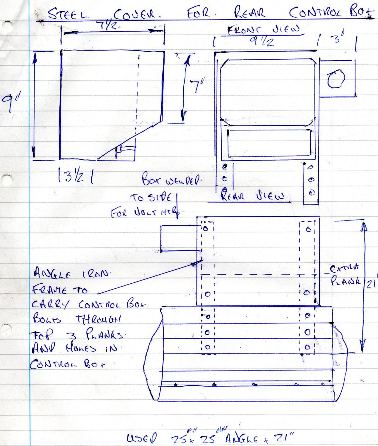
if it is could you help me answer a couple of questions i need to make the steel cover for the rear control box for the PTO driven generator did you get this cover with the parts you bought if possible can you check if my drawing for the cover is correct
Nicky
-
i use machine marts parts cleaning fluid comes ready mixed in a 5 gallon drum at reasonable price
nicky
-
Having spent a many hours taking inspiration for other peoples restoration blogs i thought i was time to start my own having spent the 10 months prior to going to Normandy for the 2014 70th anniversary on the excellent tour organized by the MVT restoring my Bedford MWR the full story of which is told here ,
http://www.yorkshiremvt.co.uk/articles/bedford_mwr/bedford_mwr.htm
on the yorkshire mvt web site it would have been nice to do a restoration blog at the time but i had my hands full just finishing the truck on time i new when the truck was first put back on the road that there was still a lot more work to do but when i started looking at other trucks i began to realize just how much work there was still to do ,this blog will cover the work to complete the truck to as it would have been when first put into service in 1942 .The most major job for this winter will be the installation of all the MWR specific parts in the rear of the truck

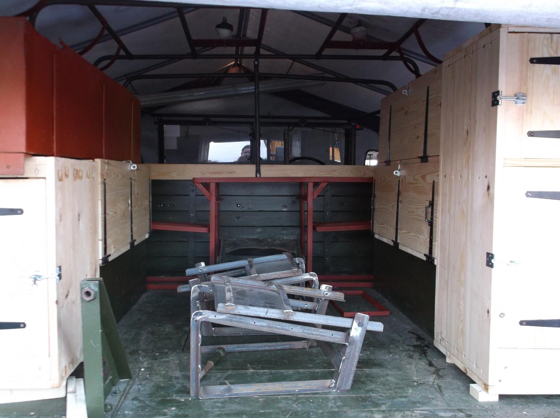
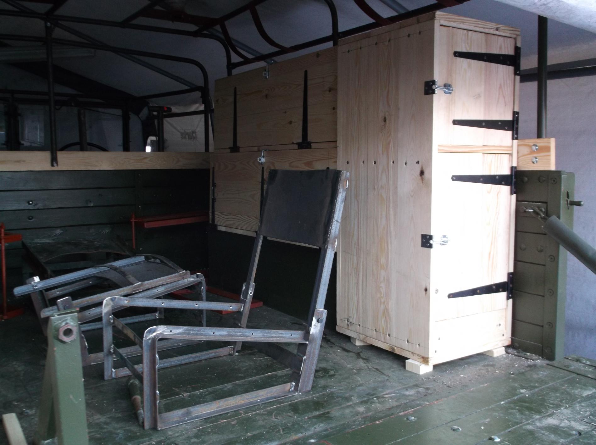
the fittings in the back are left side large tin box with canvas cover running nearly the full length of the rear body this box would have carried the various radio aerials ,wood cupboard with door to rear carried parts for the vehicle, behind which is wood box with a drop front to carry a spare radio set , in front of this is the charging control box for the PTO driven generator and the mounting to carry the no 5 generator control panel which is used to charge the radio battery's either from the PTO driven generator or the little chore horse generator which is stored in the box fitted in place of the cab step on the drivers side ,mounted either side of the radio operators table are clamps to hold the radio battery's and down the right hand side are a second spare radio box and either another long steel box for radio aerials or third drop front box similar to the spare radio box and at the rear end with the doors to the tail board another wood cupboard , fitted down the center are the seats for the wireless operator and two radio decoders ? as you can see from the other photos with a full crew of five there was not lot of room left for the crews equipment and personal stuff which why all MWRs had the spare wheel on the back and a roof rack

nicky


.jpg.8ce2d8259c790353d32af3f1b6fc0522.jpg)


Bedford MWR restoration
in Blogs of MV restorations
Posted · Edited by landrover nick
Hi Ivor
you sure contract T8102 had wireless trucks in it i think the rivets truck is either 1939 or 1940 aero screen truck my research shows the first wireless trucks as much later in early 1942 .
Jeremy as Ivor says the info for the contract number and lists of Z numbers now we know were to look is straight forward but to find a link to the chassis numbers is going to be a lot harder , was your truck built as GS originally
as i said in part seven of my restoration blog i have narrowed the number of possible Z numbers for my truck to 974 from Z 4908541 - Z4909515 i have a photo of Z4908805 this is a later truck with the sling flanges on the wheels so that reduces the list of possible numbers to 264 any body want to lay claim to any of the numbers between Z 4908451 - Z4908805
Nicky
PS are there any factory production figures of how many MWs built per month in 1942