


Bob042
-
Posts
90 -
Joined
-
Last visited
Content Type
Profiles
Forums
Gallery
Blogs
Events
Articles
Store
Downloads
Posts posted by Bob042
-
-
I'm assuming from what is left in the Milweb ad that the Lightweight & 101 together with most of the 109's have already been sold off privately?
-
how did you get on Bob i have the same fault on my new ibmu :embarrassed:
Hi Rob?
Sorry but never had the chance over Easter to do what was intended.
All being well, I will have the time next Saturday with my wife at work to test out the IBMU with the vLO fault. I am currently trying to locate replacement cards, of which I have sourced one, the real problem item for this fault I believe to be the PSU but have yet to prove it.
It is frustrating, and I sympathize with you as what happened to you was a re-run of my experience. I have however purchased a third IBMU which is functioning perfectly. In the meantime I will sell? the dead one or keep it for spares? and keep the other once repaired for back up. Not sure yet but IBMU'd out at the moment.
Will update this thread shortly.
Regards
Bob
-
Hi Iain,
Thanks, I will be trying the input module first before moving onto the cards. My plan is to start on the testing at Easter when I have a decent amount of time. I wish I could get hold of one of the extender cards! but as you say I can easily tack on test wire to the pins which is what I'm going to have to do. I'm convinced there is not a great deal wrong with the IBMU that powers with the vLO fault, its just tracking the fault down. The one that's dead of course is another story but in time I'm sure it can be sorted.
Will update as soon as I can
Regards
Bob
-
Hi Peter
Last year I replaced mine with the nearest to the original "look" I could find. They are Lucas 65ah and have found them to be excellent and fit a treat, no problem with battery box clearance. The batteries are 225mm high to the terminal tops.

This was an earlier picture just after I had fitted them. I now have the pukka brass wingnuts and covers for the leads.
Regards
Bob
-
Hi Iain & everyone else following this,
I think what I'm going to do is get myself a small lab 30v DC psu with variable voltage setting to power the IBMU and test out from the pins on the analogue and see what I come up with, I don't want to be doing it in the back of the wagon for obvious reasons. I need to try and nail what this alarm code "1.31" means otherwise I will have to go down the route of changing all the tants as listed and hope that nails it, starting with the PSU card and testing each card as the suspect tants are replaced. One thing, I don't have to do the Logic mod as there is a replacement.
How would I test the cards out of the unit? I don't see the possibility of this as I don't have the expertise and experience.
Also outside of common sense electrical safety, anything special I should be thinking about? - equipment safety too of course.
Regards
Bob
-
Some more pics of the PSU board, right hand side as requested by Iain,


Also close up of both IBEKs;

Next move back to the Analogue card and test pins as follows;

The pins are located top right of the card, the limited info I have states " The various voltages can be tested from the test pin points on the front of the Analogue Module. When working on the PSU card I normally power these individually from a current limited 24v laboratory power unit, this makes testing of the individual supply outposts much easier"
There are also 2 other pin points on the Analogue card, see below;


Next the Logic Module, 2 test pins here;

Regards
Bob
-
not sure if this works but file from widney ash attached
Hi David,
Many thanks for this, much appreciated. I had hoped it might identify the vLO alarm code "1.31" but unfortunately doesn't. Not to worry, its still very useful to have.
Do you have any other Widney IBMU info?
What we really need is the REME field repair manual.
Regards
Bob
-
Strange you should say that - I used to use a small one for the desoldering phase of surface mount repairs (in hot air gun mode). They are Ok for occasional use as a conventional iron as long as you remember to touch something earthed reasonably frequently to ensure that there is no static - I found that the catalyst bits have a relatively short life if used as a main soldering iron (so best to buy a bag of spares at the same time as the iron) and they are of course unregulated as to tip temperature so you need to be quick to avoid cooking things. For field repairs to cables and connectors they are ideal and mine has got me out of trouble loads of times
Iain
I can understand its use in cable and connector repairs but would have thought not for pecs, I am aware of the use of the hot air gun for desoldering.
However, thanks to you all for your input, this is a steep learning curve for me and I don't mind admitting it

Bob
-
Now for pics of the PSU card;

The problem areas are as follows, C14 & C26 22uF 16V tants;

C40 & C54 33uF 25V tants;

The limited info I have states that C11, C16, C20 & C38, all 22uF 40V tants are not normally a problem but "should be suspected if no output on the 12V rail" - not sure what this means as yet in respect of 12v rail and location. It suggests that these can be replaced with "normal electrolytic 125 degree C type in these positions. This would keep the cost to sensible proportions where low ESR would not seem to be prime requirement" - again not sure how this translates?? pics of these below, they are quite large and apparently expensive;


Now the big question: Where my other IBMU powers up but reports low voltage, error code 1.31, vLO, does this fault lie within the PSU where a tant is reporting low voltage input even though the voltage input is proven correct, or does it possibly lie within the Logic module?
If I can identify this error code and its reporting source then it's cracked.
I will order the parts I need in the coming week.
Bob
-
Have you looked at gas soldering irons?
Sorry but you've lost me, I'm talking about replacing capacitors on circuit boards and I cannot for the life of me see where a gas iron comes in unless I want to fry the board - or am I missing something ?
-
Hi Iain
There's one at RAF Waddington (one of my former stations) which is 35 miles away and I know is very well supported.
I will probably go there, its 'home' ground to me if you get my drift and my mate from the past life is stationed there too.
Thanks for the club finder, interesting there are no contact details for Thorpe Camp, I would like to have gone there as not been that way for years. We shall see. Shame Felixstowe is so far away.
Regards
Bob
-
I put your name on the form!
Hope you don't mind, btw I have found a new logic module for the IBMU!
Only £4.99 so nothing to lose.
I don't want a cheap iron, needs to be something decent so don't mind spending, there seems to be some good ESD non Weller irons for around £50 on gleebay, will post link to see what you think.
With VMARS, thanks for the welcome but I don't have a c/s yet, for the last couple of years have just tuned to dummy load but need to move on, past life must be left behind, I'm not a radop or RSI any longer plus all the rest. I believe I must apply to OFCOM initially for c/s then take the RSGB exams. I tried to contact my local society in Melton but nobody bothered to come back to me, also tried Colin at Thorpe Camp but similar. On their site there are some contact numbers for others so will try them this week for exams.
Regards
Bob
-
Bob
I always use the Weller temperature controlled static protected irons - got issued with one on my first day at work and they have always been reliable and never destroyed anything (they have an earthed tip so are static safe if correctly installed). The WES series are I think the current ones and are between £50 and £100 on e-Bay - I still love my old EC4100M controller with EC1301 iron that I bought from stores at work about 20 years ago.
The cable tie is probably not a repair - if the chip is the EPROM holding the IBMU firmware it needs to be socketed for upgrades and then needs to be secured so the chip stays in despite the rigours of military use.
These days there are good low ESR electrolytics in similar sizes to the tants that dont have the same failure modes so you should probably consider replacing with 10uF rated at least 30 volts - something like: http://www.rapidonline.com/electronic-components/10uf-35v-5mm-micromin-electro-capacitor-11-1512
Best Regards
Iain
Hi Iain,
Have had a look at the Weller gear, wow! very nice but by the time I've got all this kit I might as well buy another IBMU from a certain gleebay trader which is not what I want to do (mine do not come from him). Do I really need an ESD iron? If so then fair enough. Unfortunately our work ones are not suitable as we deal with LV switchgear and traction products. We used to build for BT with all the fine stuff but no longer so the irons have all gone with except a couple which are not suitable.
Bob
-
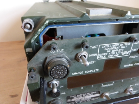
Just to give a bit of perspective to all this, here is the radio fit in my LWT FFR, 19 HF 27, contract & build date 1979, ex Gurkha Field Force HQ & Sig Tps, Hong Kong 1980-1997;

Everything is in full working order - except you know what, hence I'm a bit driven about it.
In the URS battery box are a pair of 15 month old Hawkers for the big sets;

Today I posted my VMARS membership application.
Regards
Bob
-
Hi
That looks like a 2A 109 if I'm not mistaken.
I wish I could help in the short term but I cannot think where my Larkspur FFR radio fit manual has got to.
One thing, and your vehicle looks really nice from the pic and this is no criticism, is that for a 2A FFR the dexy is wrong. The early Dexy fitted to 2A 109 FFR's had a lattice type work in the middle. Many years ago in my past life, the NITAT Hythe & Lydd range wardens had one and it was absolutely mint. This would be about 1989-91 I guess. Last year on glee bay there was a set for sale and I just wish I had bought it as it went for next to nothing. I didn't because I don't have a 2A 109 FFR but would love one.
I will do a trawl and see what I can come up with.
Regards
Bob
-
The Analogue module problem areas according to my limited info are the 10uF 25V tants C1, C9 (below C12), and C12 as shown below;

Also C5 & C8, again 10uF 25V as seen below;

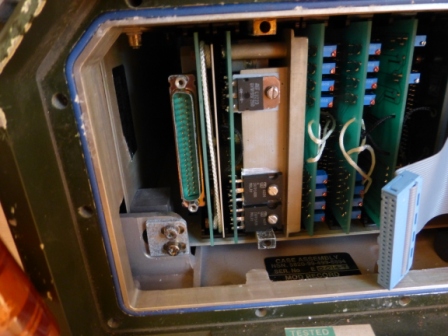
Next is the Logic module, which is the far right one with the blue input loom (which can be disconnected as previously described) as seen below, note the interesting repair with the cable tie!

Apparently there is only one problem tant on this, C1, 33uF25V, see below;

As previously mentioned, the other problem area is the big PSU card which I will disassemble this weekend and post the pics as well as details of the problem tants. Also some more info on the Analogue card to come with advice wanted on how to test.
Anyone any soldering iron recommendations??
Regards
Bob
-
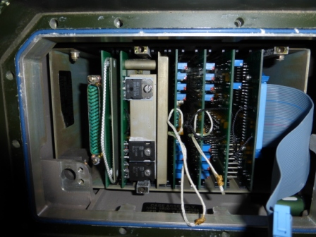
This morning before going to work I pulled one of the cards and hey presto, I don't have an ID problem because its stamped on the card which pec module it is! The card I pulled was the filter module pec (far left from front) and it appears perfect, no sign of damp damage at all. The limited info I have is that this is not one of the problem area cards.
I'll put some pics up tonight.
Bob
As promised below;

Above is the filter pec, this card is not normally known to be a problem according to my source.

Filter pec NSN if anyone needs it.
The next pec from the left is the PSU, big piece of kit with cooling plate, which I will remove in due course, this is one of the common problem areas, details to follow, see below;

Third card from left is one of 2 Driver modules, they are both the same, same NSN, not normally associated with problems according to my source notes, see below;


Next from the left (fifth) is the Analogue module which is a problem area, see below. I will detail the problem tants later.

Got to go, Wife chasing me!
Regards
Bob
PS, NEED SOLDRING IRON, any recommendation's? Thinking of 30W variable temp. I know I need solder sucker too. Will be using standard 60/40 tin lead solder.
-
Hi Andy
Thanks, good advice & much appreciated, never thought of that, Doh!
The thing about this IBMU is that it is the one that does not power up which is why I'm using it as the guinea pig to get the knowledge prior to attempting repair to the one that does power but keeps going to low voltage fault. Now the question I'm asking is why does this one not power up? Has the damp ingress damaged it beyond repair? The cards look in good condition with no sign of corrosion.
Take your point about the flexi pcb's Iain, have checked tonight and look ok. Gold plated leads, so what solder should be used, as Andy points out the original is highly probable lead?
A couple more pics;
Not sure what this pin is for, if you recall I said ignore the two retaining Allen screws earlier when removing the inner retaining plate. It actually locates into a graphite grey coloured block fixed to the bottom left of the card casing, you can just see it in this pic. Is it just for inner casing locating and retaining purposes? Again the pin and screws have suffered from moisture considerably;

If somebody confirms I'm meant to pull the cards using the cords I will do, but I'm wary to do this as I don't want to damage a potentially repairable source of replacements??
Regards
Bob
-
Hi Iain, and anyone else watching this who may be able to help,
More pics to come, but now I have the problem of identification. There are a number of cards which have cord attached to them, some is white cord, some black. I presume the cord is there in order to extract the card for replacement or repair? In saying this I assume the cards connect into the circuit board on the back plate?. I need to I.D. the PSU card, Analogue module and Logic module as they are the main areas of concern apparently. I have the tant numbers I need to replace.
Bob
-
Couple more pics from yesterday,

Control panel pecs NSN

Power input module NSN
Regards
Bob
-
In this section we will disconnect the output loom together with some observations on what I found.
With the blue control loom disconnected, open up the front panel to the left of the unit casing;

This will expose the inner retaining plate behind which sits the output loom connector plug and the main inner components of the IBMU;

You will see the inner plate is held in place by 3 Allen bolts, ignore the two to the bottom left below the output loom. You also may be able to see here the evident whitish corrosion to the 3 Allen bolts;

To the bottom right of the retaining plate you can see the evidence of moisture staining around the desiccant unit. Obviously the unit has not been serviced for some time and I don't know if replacement desiccant units are available. I am surprised at the evidence of moisture ingress to the unit, as I have taken apart much older Clansman stuff before and everything was as dry as a bone and shiny as the day it was assembled. A closer look at one of the screws below;

Undo the 3 screws and withdraw the retainer plate;

This will expose the output loom plug and its 2 retaining screws to the left and you get the first proper peek at all that lies inside the casing;

Remove the 2 retaining screws from the plug;

Gently ease the plug from its housing, the front control panel is now free;

That's all for now, otherwise I shall be in trouble. more to follow soon.
Don't be afraid to have a go!
Regards
Bob
-
Time to have another go.
First of all you need a 3mm Allen key then undo all the retaining bolts on the front and rear plates, they are all captives so keep unscrewing until they run loose, you cannot lose them. Do not try to remove the back plate at this stage. The front control panel will now be loose.
Using the carry handle, gently ease the front panel away from the casing;

Behind the front panel is the controls pec with 2 connecting looms, a blue control loom to the right, then the output loom to the left.

Next disconnect the blue control loom. Do this by lifting on the retaining catches to the top and bottom of the plug;

Pull back on both catches at the same time and the plug will self extract, don't worry if there is a bit of resistance at first, just keep pulling back on the catches to their fullest extent and the plug comes free;


Easy :-)
I'm going to post this section now as I don't want a repeat of last nights disaster.
Bob
-
I have tried to post all the pics tonight over the last hour or so and it has crashed so will have to leave until tomorrow as fed up now as you can appreciate, this is not the first time I have had problems posting on this site.
Bob
-
Iain,
Are you on about the white modules on the psu card folding back because of the tant short circuit? If so what's the prognosis? are spares available? I have yet to find out the issue, and need to understand what this means.
Very interesting,
Regards
Bob


Auction of 30 years of collecting military vehicles
in Heads Up: For Sale!
Posted
Thanks for the info John, much appreciated.
Regards
Bob