


BenHawkins
-
Posts
861 -
Joined
-
Last visited
-
Days Won
3
Content Type
Profiles
Forums
Gallery
Blogs
Events
Articles
Store
Downloads
Everything posted by BenHawkins
-
This sounds like a good method; I will have to give it a go. I can understand the acidic nature of the vinegar but what does the salt do? Is it just an abrasive?
-
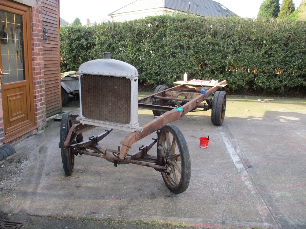
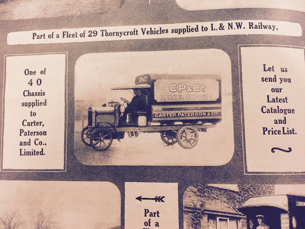
The back axle is still fitted with the complete worm-drive so that makes it a better start than either of my Dennis projects. My good friend Mick had what appears to be a "new old stock" radiator in his garage and it appears to be the perfect shape and size despite not having the Thornycroft badge. CP & Co vehicles often had a CP & Co badge in place of the makers radiator badge. So the engine, gearbox and steering box are the major components on the shopping list to make this a viable restoration. I have a 1916 instruction book and illustrated parts list for the "X Type" so I am sure there were earlier instruction books. It would be nice to have them for both the pre-WWI and post-WWI Type BT so I could see if any parts were common between the two. Were all the impressed vehicles repainted eventually? I have seen a few photos of CP & Co lorries in military service but still in their original livery. There are various colours of paint remaining on the chassis but mostly it is red, green, beige and rust. I will keep you informed of markings as I find them. I expect this project will mostly be collecting (parts and information) for a few years whilst I complete the Dennis projects. Perhaps it is another "impossible" project; there is only one way to find out.
-
Another project arrived at my house this week. This time a fairly light-weight worm drive Thornycroft. The wheels have CP&Co asset tags. I seem to have ended up with another red lorry. 40 of these were purchased by CP&Co from Thornycroft and were delivered between the end of 1913 and early 1914. Thirty of them were impressed by the war office so by the end of 1914 only ten remained in the Carter Paterson fleet. On the CP&Co stock take they are listed as 35cwt and the dimensions match those of a pre WWI type BT (the post WWI version appears to be bigger and heavier). I have not yet uncovered the chassis number but even if I do it may not help with identifying if in was one of the 30 transferred to military service.


-
The magneto is missing both its aluminium flip top covers. The large one is broken and the small one was completely missing. I started by roughly making a piece of aluminium the correct shape on the milling machine. Then tidying it up with a file and emery cloth. It turned out my sketch was not quite right so I had to mill some more away and file some material from the hinge section.


-
I cleaned back the welds with a flap disc fitted to an angle grinder. Then put the pipe back in position. The flange was bolted up and the pipe pushed fully home. I was then able to drill through three of the holes for the rivets. Unfortunately the rivets I have in stock are not quite long enough for the application.


-
It turned out nobody could bend the exhaust pipe the way I needed it as the bends were too close together. So I trimmed some bent pieces of pipe to length. Then tacked them together with my MIG welder. After checking it fitted together I welded between the tacks.


-
I had to improvise a large screwdriver for the carburettor jet. It was quite tight but now it is out and can be cleaned. As can the adjustment screw. Many of the carburettor parts have been scrubbed clean. The levers are very tight on the spindle so I might just leave them in place as there is nothing obviously wrong with that section.


-
The carburettor jet requires a screwdriver bigger than the ones in my collection to remove so I need to remedy that this week. The petrol inlet fitting looked like 3/8 BSP but when I tried a nut, it went on but did not feel like a good fit. Measuring the thread it is 5/8" OD x 18 TPI Whitworth form so I need to make a nut to fit. That is as far as I got with the carburettor this week. I did fit the gland packing to the Rolls-Royce 20/25 pump but have also purchased another type of pump from Australia that I hope will be a better fit in the available space.

-
The float also appeared to be in good condition. The carburettor has a water channel through the casting to allow it to be heated by including it in the radiator circuit. The banjos and bolts were removed and a small amount of rusty deposit removed. The choke spindle is bent and one of the rivets missing so I cut the head off the remaining one so it could be removed. for straightening and drilling out the broken rivet.


-
As with the rest of the engine the carburettor has been painted with Hammerite type silver paint. Most of it fell of reasonably easily but the texture in the top of the float bowl allowed it to bond fairly well. So I poured some cellulose thinners into the casting and picked the paint out with a scriber before applying some Brasso with a toothbrush. The weights and needle are in good condition.


-
Pieces of gland packing material were cut to length. These were inserted around the tap spindle. The gland nut was tightened and some solder nipples and 3/8BSP nuts were found to fit the inlet and outlet.


-
The element then screws onto the tap. The bowl was fitted and the tap removed. The needle and shaft were cleaned up with some emery cloth.


-
I had a similar type of Enots petrol filter with a filter element to copy. I turned the brass carrier, put slots in the top and milled a hexagon on the bottom before sawing it from the bar end. It was then a case of cutting a piece of brass mesh and soldering it onto the carrier with a soldering iron.


-
I checked the angle required for the 1/2" OD radiator overflow pipe then used these pipe benders to put a 65 degree bend in it. After trimming the pipe to suit and soldering the nipple on to the end it was fitted to the radiator.


-
A ceramic chip gas forge; hopefully get that up and running one day. Could be quite useful for the ironwork on the 1908 Dennis.
-
Moving on to the exhaust. The middle section goes from the exhaust bracket to the silencer so is a simple straight length of pipe with one of the cast iron flanges made previously fitted to one end. I think these were originally just riveted on but I thought I would silver solder it on as well. I had two attempts at warming it up and don't think I left much clearance so failed to get the silver solder to flow. I then could not get the flange off the pipe so decided I would just proceed with the riveting, starting with drilling holes 180 degrees opposed. To support the rivet on the inside I used a ball nose slot drill to put a dimple into a piece of steel bar. With the help of the glamorous assistant to hold the pipe in position I was able to form the head with the aid of the appropriate snap and a hammer. Finished item.


-
I didn't get it to follow the line exactly so finished it off with the belt sander. Before repeating the procedure for the other line.


-
I drilled the sides of the bulkhead for No.10 screws to fit the door pillar. Then used a string line to mark the line from the side of the cab, and a line 2" long normal to that to carry the door hinges. The next step was to plane roughly to the first line.


-
I worked out that I needed to use a shim between the aluminium guide and the roller to ensure the guides followed the point of bend correctly (rather than the circular cross section in fact being about 1" in front of where the pipe was being bent). I was then able to move onto soldering the first pipe bend to the fitting at the top of the engine. An offset bend was made and trimmed to length. Lengths of hose and pipe clamps were prepared. And the parts fitted. There are still the lower connections to make but the pump needs to be fitted first.


-
Following on from the pump, I need to link the engine up with the radiator. Pipe benders for large pipe were looking reasonably expensive even if I just wanted to hire them. A poorly listed internet auction came to the rescue and I purchased this one locally for about the price of a round of drinks. The only part missing was the pipe support so I found a piece of scrap aluminium from under the bench and made one on the shaper. Initially all I was able to make was modern art (aka scrap copper pipe with creases)


-
The pump shaft was difficult to drive out; when it finally did come it was only by breaking this aluminium bush. The shaft was very well corroded into it so in the end I had to split the remains of it to get it off the shaft. But at least it was an easy part to make. And then just needed driving into the pump body. I found I did not have the correct size gland packing so it will have to wait until I go shopping.


-
You may remember I purchased the water pump from a Rolls Royce 20/25 to use as I have not been able to find anything better. After heating the drive yoke up I was able to lever it off the pump shaft splines and remove the gland nut. The nice thing about this pump is that there is plenty of information available. The impellor is fitted with a taper and thread; this was rather rusty so there is little chance it will come off. So I decided to remove all the gland parts so I could slide the shaft out with the impellor.


-
After everything was cleaned the parts were put back together. And finally the toggle was put back on and the switch was checked with a digital multi-meter.


-
Taking all the parts out and laying them down it became obvious that someone had tried a repair before and replaced one of the insulating washers with one made from brass. This was obviously the problem. So as the remaining insulator was looking fairly poor I turned up new ones from a piece of peek I had left over from another project. Then refitted the terminals.


-
I decided it was time to start on the extremely complicated electrical system (4 HT leads, one magneto and two wires to the ignition switch). The ignition switch was picked up at an autojumble a few years ago but it seemed to be closed circuit no matter what position the switch was in. Before the body could be disassembled the pin from the middle of the toggle had to be removed. And then it could be seen that it worked by a brass roller making the connection between the terminals.


