Doc
-
Posts
243 -
Joined
-
Last visited
-
Days Won
6
Content Type
Profiles
Forums
Gallery
Blogs
Events
Articles
Store
Downloads
Everything posted by Doc
-
Well spotted! 1923 J type.
-
Driveshaft and gearbox removal This started as an exercise to free off the gearbox. First the brake callipers and their operating linkage were removed. Next the flexible couplings of the input driveshaft were dismantled along with the short coupling and part of the Hooke's joint of the tail shaft. Removal of the gearbox lid revealed the internals to be rust free and covered in thick black oil. Liberal application of straight 30 from an oil can soon had the change-speed gears sliding on their splines. Input and output shafts were also soon free, if a little tight on the oil seal felts. Careful inspection revealed no damaged teeth on any gears. The retaining bolts were withdrawn and the change-speed rods uncoupled in preparation for the removal of the gearbox. The oil filler neck was also unbolted to avoid it accidentally coming into contact with the chassis rail, before the gearbox was lifted out of its cradle. Once safely on the ground, attention turned to the brake drum. This required a bit of persuasion before it could be withdrawn. Not many things argue with the big hydraulic puller.


-
All accounted for. Tea chests contained as follows: Original headlamp brackets, fabricated side light brackets, one original rear mudguard bracket New-cast aluminium bonnet supports for mounting on the bulkhead plus patterns Spare radiator side casting plus the pattern Plug lead conduit rusty remains including the brackets Valve chest covers - enough metal to make one out of the two Fan shroud remains Torque tube ball joint spun brass cover (cracked / broken - repairable?) Numerous linkage pins and old nuts and bolts from which grover washers have been recovered Some spare brake linkage parts. In addition, I have the remains of the engine under-pan and original front and rear mudguards, suitable for patterns. Will endeavour to take photographs next time I'm back East. Strangely I have no front mudguard brackets. They were on the lorry when discovered, but haven't survived.
-
The tea-chests keep on giving! The remains of the flexible hose that connected from the engine to the Rotherhams oil pressure tell-tale on the dashboard, together with my recreation (using the original nuts). All is not as it seems: the outer containment is spiral wound conduit. Hidden inside is a length of ptfe tubing pressed onto brass barbs. The whole assembly was soldered together. As I neglected to take photographs of the work in progress I have included a section view generated in 3d cad. The socket coupling between the tell-tale and the first elbow has right hand thread at one end, left hand thread at the other. Union can be tightened without torque transmission to the hose. Ingenious.


-
Front bonnet support. More treasure from the tea chest: most of the original bonnet support one original bracket with a rusty piece of the same angle iron riveted on. Also present, a reproduction angle iron bonnet support welded to two 1/4" thick brackets. After a little study it was clear that neither the new support nor the brackets were the same shape as the old original. This is one of those situations where attitudes to restoration have changed since the 1970s - I looked at the rusty remains and concluded that they could be repaired. One side complete enabling measurements to be taken. New metal cut and welded into position. Just the rivet holes to drill. Original and pair of new laser cut brackets for comparison. In top coat. Bolted to timber support to aid handling while painting.


-
More rusty tea-chest treasure: full set of bonnet catches. A little bit of heat freed everything off. Springs past their best. Replacements sourced from Flexo Springs at Kingswood. Four new shoulder bolts required. Brass nuts reused. Painting... in my kitchen in Bristol One more job off the list.


-
Amazing what turns up... the inserted list describes all the significant differences (apart from chassis length) between my lorry and the description in "The Automobile Engineer". 20ft. 10in. is essentially the same measurement as the 21ft. quoted in the aforementioned publication. General Arrangement drawing from The Automobile Engineer September, 1916. A last minute trip to Suffolk this weekend and a bit of a rummage around, here's a couple of images of the logbook.


-
Greasers The steel bodies of greasers bearing the stamp "KARR" WDS 11506 remained in a few locations: one rear wheel hub, king pins and one spring saddle. Three out of four bearing the part number 11179 remained on the short coupling between the gearbox and prop shaft. The former were threaded 1/2"BSF, the latter 5/8"BSF with a long shank on account of the thickness of the coupling. Original greaser bodies The body thread was 1.1/2" x 16 tpi whit form in both cases. Fortunately I was able to source a tap and die of this thread form. I have made three new steel bodies and ten new brass caps. Spring shackle pins and track rod pins are one piece with their greaser body. These are an odd thread. 16 tpi whit form but measuring 0.9" across the crests of the threads. The eagle-eyed amongst you will have spotted the two tea chests strapped to the chassis on its arrival. One of the items of treasure contained within was a worn spring shackle pin. I milled flats across the threads in an attempt to make a crude tap. A piece of brass was put up in the lathe, faced and bored. Whilst I did succeed in cutting a thread with my home-made tap, it was hard work, so I dug deep and ordered custom made taps from Avon Tap and Die. These made short work of the required 16 new caps. Most other locations were devoid of greasers. The parts book states these were Rotherhams No. 2 Again the stem thread is 1/2" BSF but the bodies are M24x1.25 for which taps and dies were again available. I turned a batch of forty of these after 5 pm on the Harrison M300 in our R&D machine shop at work. Several nights work, I hasten to add. Taps and die as described above New and old steel bodies, new brass caps. Reproduction Rotherhams No 2 greasers


-
Following the broken chassis discussions I spent some time with my photocopy spare part list to see if there was evidence that Clayton and Co. recognised this problem and sought to remedy it. The book, which has neither date nor revision number, covers chassis numbers from 1000 to 2001 onwards. Documented changes were made as follows: 1079 Gearbox modifications especially to strengthen the lay-shaft, also improvements to the rear coupling and its attachment. 1104 Bonnet catches 1204 Cardan shaft and torque tube changes 1208 Rear axle spring seat and bush 1326 Steering ball-joint adjustment strengthening and gearbox oil filler change 1328 Front and rear mudguard brackets 1351 Dashboard support brackets and related parts 1476 Steering box casing (also requiring changes to the bonnet) 1501 Fuel filter change from Enots to one of their own manufacture 1651 Engine mounts. Off-side is rigidly bolted to the chassis via spacer blocks. Near-side mounts changed to introduce flexibility. Front and rear mounts discontinued, replaced by an in-board support plate with centrally mounted pivot point and associated chassis-mounted bracket. One curiosity about this change is that there is only one part number for the near-side chassis rail (or "Longitudinal Runner" in Clayton nomenclature) - 9302. Unchanged off-side is 9303. Out of sequence is the Rear Cross Member 10336, but again no earlier number for this part. I wonder why issue control for chassis part numbers was treated differently to other parts. Perhaps replacement near-side chassis rails were drilled for both engine mounting styles. Alternatively, if a new chassis was supplied, perhaps Clayton and Co. insisted that the near-side engine mounting was upgraded at the same time. Another curiosity: different chassis lengths are not mentioned in the parts list when it is clear that both a short and long version were produced. Perhaps the long chassis was introduced at some point after no. 2001? 1726 Clutch operating bridle and clutch stop nut 2001 Rear axle first reduction shaft and bearings There are also proposed changes to the cooling fan, pulley, spindle and bearings but with no cut-in number.
-
Roy, Thank-you for the clarification. Regards Doc
-
Roy, " In September 1915, the Director of Transport in France described Karriers as being ineffective due to lightweight chassis that kept breaking. " I understood from this statement that Karriers were routinely subject to broken chassis thereby rendering the whole marque ineffective, not that the Karrier was no better, no worse than other marques in this respect. It was the differentiation of the Karrier chassis over others in this way that I found odd. That all motor vehicles were, to a greater or lesser extent, prone to chassis breakage is, as you suggest, no great surprise. What is the origin of the 1915 quote? Is this an appraisal of the whole transport fleet? Are reprint copies of this report available? Sounds like it would make interesting reading. Doc
-
Roy, Lots of interesting information there, all new to me. I am sure I read somewhere that the torque tube rivets were prone to working loose, though have forgotten where that was. The chassis breakage would seem odd given its massive proportions - 8" x 2.1/2" profile for the bulk of its length. Perhaps the 1/4" plate thickness was deficient, or there was insufficient cross bracing. Certainly makes the Leyland RAF type chassis look fragile in comparison.
-
The very same, though has been through two further owners before it came to me. Compared to many of the heroic restorations reported on this forum, yes it is substantially complete.
-
I have seen that photograph somewhere. No idea what became of the removals box...
-
The scope of this restoration project is rather different to many of those shared on this forum. I am extremely fortunate in that the chassis is largely complete. Much work has already been undertaken. That which remains falls into discrete categories: 1) jobs not started, 2) jobs completed but which have deteriorated over the last 40 years 3) jobs not done to an acceptable standard. I don't mean the last category to sound critical. Firstly and most importantly, this vehicle was saved. Work started over 40 years ago. Budgets, the decision whether to repair or replace, availability of services and techniques were all very different compared to today. I am typing this entry on the same lap-top computer that I also use to run 2d and 3d cad packages. Laser cut steel profiles can be produced as readily as printing. New castings can be produced directly from cad models via 3d-printed resin-impregnated sand moulds. That being said, there are other things which are more difficult / no longer available. I am very fortunate in that the lorry has been fitted with new Dunlop solid rubber tyres. These were still available in the 1970s. Today (without recourse to a stash of new old-stock tyres under the bed) one has to make do with moulded and profiled rubber. Whilst good work can be done, they're not the same as "real" tyres. For other restoration projects I have had batches of BS190 Whitworth nuts and bolts manufactured. I generally order them in 10 ft quantities as EN8 hexagonal bar comes in random 10 ft lengths. For this project, a quantity of 1/2" BSF bolts (without GKN on the heads) and single chamfer nuts were required. I was informed that 0.82" AF EN8 hexagonal bar is no longer available so he would either have to use 13/16" AF or machine from the round on a mill-turn. I opted for the latter. In category 1: Bodywork and Cab Bonnet, bonnet catches, tappet covers, plug lead conduit, radiator stay, under pan. Silencer and exhaust pipe Control linkages, fuel pipes etc. Greasers: all brass greasers (Rotherhams' No. 2) missing. Brass caps from steel bodied greasers of Clayton and Co's own manufacture missing. Magneto bracket and clamp missing. In category 2: Paintwork. The hideous blue undercoat has done a good job of holding back the rust on the chassis, but has to go. Or at least be sanded back and covered up. On other parts the rust is coming through again. Engine and transmission. I understand that attention had been given to the crank and bearings, also the oil pump. A previous owner reported that the engine was tight and wanted "to go on the belt" but by the time I purchased the lorry the engine was seized from standing. The clutch, gearbox and transmission brake were also stuck. In category 3: Bulked support buttresses. Originals were a comparatively thin-profile steel casting. One has to imagine that these were seriously corroded as they had been discarded in favour of some rather clumsy fabrications. Whilst it is true that, with the floorboards in place and the cab door shut, they would be hardly visible, I felt that more authentic replacements were required. Bonnet support. In common with many vehicles of the period, there is an angle iron support for the bonnet immediately behind the radiator. Fortunately I had the remains of the original support and one bracket. A new one had been fabricated and welded to new folded 1/4" steel brackets. It was apparent that the profile did not match the original. In addition the folded brackets were not the correct shape as they did not fit. The above was an initial assessment. Other problems have been discovered during the course of my restoration work - these will be discussed at the relevant time. Sorry, that was a lot of words. Turning first to the body and cab. Whilst copious photographs were taken during the extraction and recovery of 2927, no drawings of the cab and body remains exist. Neither is it possible to know if these remains were from the original bodywork. So what should I build? Given that this was most likely a civilian vehicle, the temptation would be to build an enclosed cab akin to that in the Commercial Motor advertisement. However, in the absence of drawings or dimensions, I feel that the best I could create would be a pastiche. For an open War Office pattern of cab, there are numerous photographs from which to deduce the constructional details. Also these appear to have been of standard dimensions - 75" wide x 47" tall; certainly Leyland and Thornycroft cabs appear to conform to these dimensions. Therefore I have decided that I can build a more faithful replica of a War Office cab than a civilian one. Similar considerations apply to the body. So I have taken the following approach. First I have created a 3d cad model of the chassis, bulkhead, etc. Next I have constructed the seat box to the above dimensions, and placed it on the chassis to straddle the fuel tank with the back boards located where rust scour marks are visible on my chassis. Thereafter I have experimented with different timber dimensions and iron bracket sizes to give a body that resembles those in period photographs. Model of my chassis and bulkhead With seat box in place Now with a body Perhaps a bit "odd" as I have opted for the earlier open-planked design on a later long chassis (which, by rights would more likely have had fully planked sides). Personal preference, though since I have yet to order any timber, I still have time to change my mind. Have placed 3 steel hinges on the tailboard. All coach bolts 1/2" Whit with 0.92"AF square nuts. In a photograph of a lorry with this style of body (kindly provided by the Goslings) the heads of the coach bolts are clearly visible. This model has stanchions supporting the headboard, to the same pattern as on the sides, but this seems to result in too great a clearance between the back of the cab and the body. So perhaps the headboard construction was similar to the tailboard - fully planked with iron strap reinforcement. In due course I will create this in model form for comparison.


-
What an amazing collection of period material. Thank-you all! The rear end of my chassis has been replaced - presumably the original was quite rotten. As I do not have the remains, I can only trust that the replacement is the same length as the original. Rear view of 2927 chassis. New metal starts behind the arched cross member. (Look carefully and you can see where a patch has been let into the off-side bottom) Note trial - fitting of new laser cut lamp brackets, also new "fake" rivets. Drilling "rivet" holes through jig. Machined lip was intended to hang on the edge of the chassis rail, but a weld bead got in the way... Tapping "rivet" holes Fitting "rivets" A detailed article published in the September 1916 volume of "The Automobile Engineer" gives the following dimensions: wheelbase 14ft., track 5ft. 6in. overall length 21ft. A general arrangement drawing when re-drawn based on 35.5 mm across the chassis rails = 39" puts the position of all cross-members except the rear one in reasonable agreement with my chassis, but mine is 21" longer. An advert published in a 1919 edition of Commercial Motor shows a lorry with an enclosed cab and a body of similar pattern to those supplied to the War Office. Illustration from 1919 Commercial Motor advertisement One detail difference between this image and many of the images earlier in this thread is that the illustration shows a body supported on 6 bearers whereas those in the photographs had 5. I had wondered if the post-war civilian chassis were longer than their military counterparts. However, I note that the body on the lorry depicted in the 1917-18 Christmas advertisement also has 6 bearers. Among the details that have led me to conclude that mine is a civilian lorry are: no body mounting brackets (or holes for them) no sprags, no water-cooling on the transmission brake, base coat paint colour is black.


-
Thank-you to everyone who has shared information. I had not seen the "Motor Traction" report before. I have a photocopy of a parts list, also a detailed article from the periodical "The Automobile Engineer". There's also interesting articles on the Karrier lorry and Tylor engine in the Commercial Motor archive. I also stumbled across this report in Implement and Machinery Review:

-
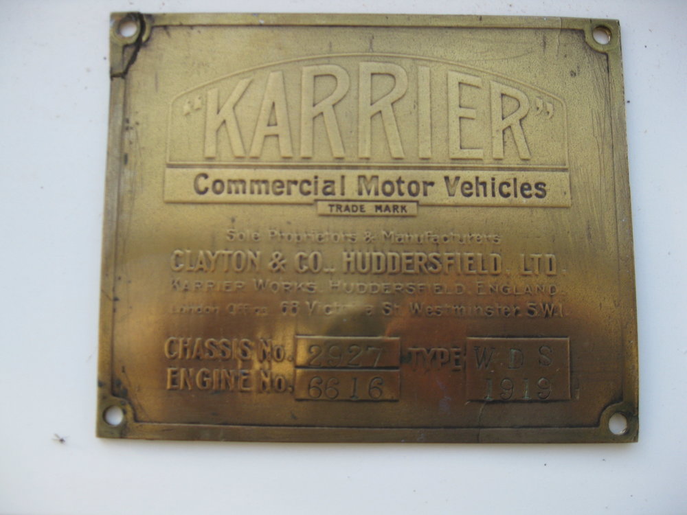
Clayton and Company of Huddersfield supplied several of their 3 ton Karrier "WDS" lorries to the War Office for use at home and overseas. It is unlikely that mine was one of them. It is, however, considered to be the sole survivor of its class so on that basis I thought it would be of interest to hmvf readers despite its tenuous connection. Chassis plate for Karrier WDS 2927 of 1919 WDS no. 2927 was discovered at Manor Farm, Appleton-le-Street, Malton, Yorkshire in 1977. Somehow the 1970s are now 40 years ago (if anyone can explain how that happened...?) Since that time 2927 has had several owners, coming into my possession in 2018. I hope to finish the restoration of this unique vehicle. As Found, September 1977 Recovery, 1977 Some history: It was road registered AK6063 on 29th January, 1921. A continuation log book shows that whilst in the ownership of James Fairbank of Manor Farm it was taxed until 1936. A petrol ration was claimed for the vehicle during the period 1943-4. One mystery to be solved: AK is a Bradford registration. Why not CX (Huddersfield - where made) or BT (Yorkshire, North Riding - where found). Did the lorry have owners prior to Mr Fairbank? Any information that forum users can share on Karriers in general or 2927 in particular would be greatly appreciated. Arriving at its new home November 2018