


.png.13c2ec34f1c53365a25f5885333b02b8.png)
johann morris
-
Posts
602 -
Joined
-
Last visited
-
Days Won
33
Content Type
Profiles
Forums
Gallery
Blogs
Events
Articles
Store
Downloads
Posts posted by johann morris
-
-
Always wanted one and now all I have to do is decide which version it was and rebuild it, easy....not. The QLW had crossed my mind but it would have to be one of the first 400 according to Barts book as I cant see any of the air portable features. I suppose someone who knows the small differences in the chassis mountings would be able to tell. That is, of course, unless there is a list of which chassis became which model.
Anyone?
Jonathan
-
A new addition has just arrived, Chassis number QL 43190 so produced in 1945 and looking at the winch gear, I think its a QLB but other more knowledgeable members may know better. The crane / jib is obviously a post war addition. If anyone knows differently I would love to hear as Bedford's are all new to me. I have just always wanted one.
Jonathan


-
I am after someone to transport a Bedford QL from Kelso to Mid Wales.
Jonathan
-
Thanks Degsy :thumbsup: Nice to hear from another vehicle owner in Wales. I find a little bit of self imposed pressure always helps the project along.
Jon
-
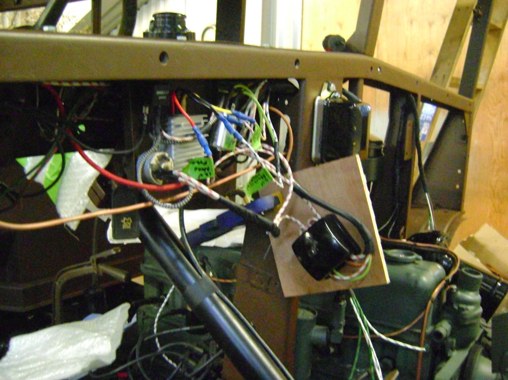
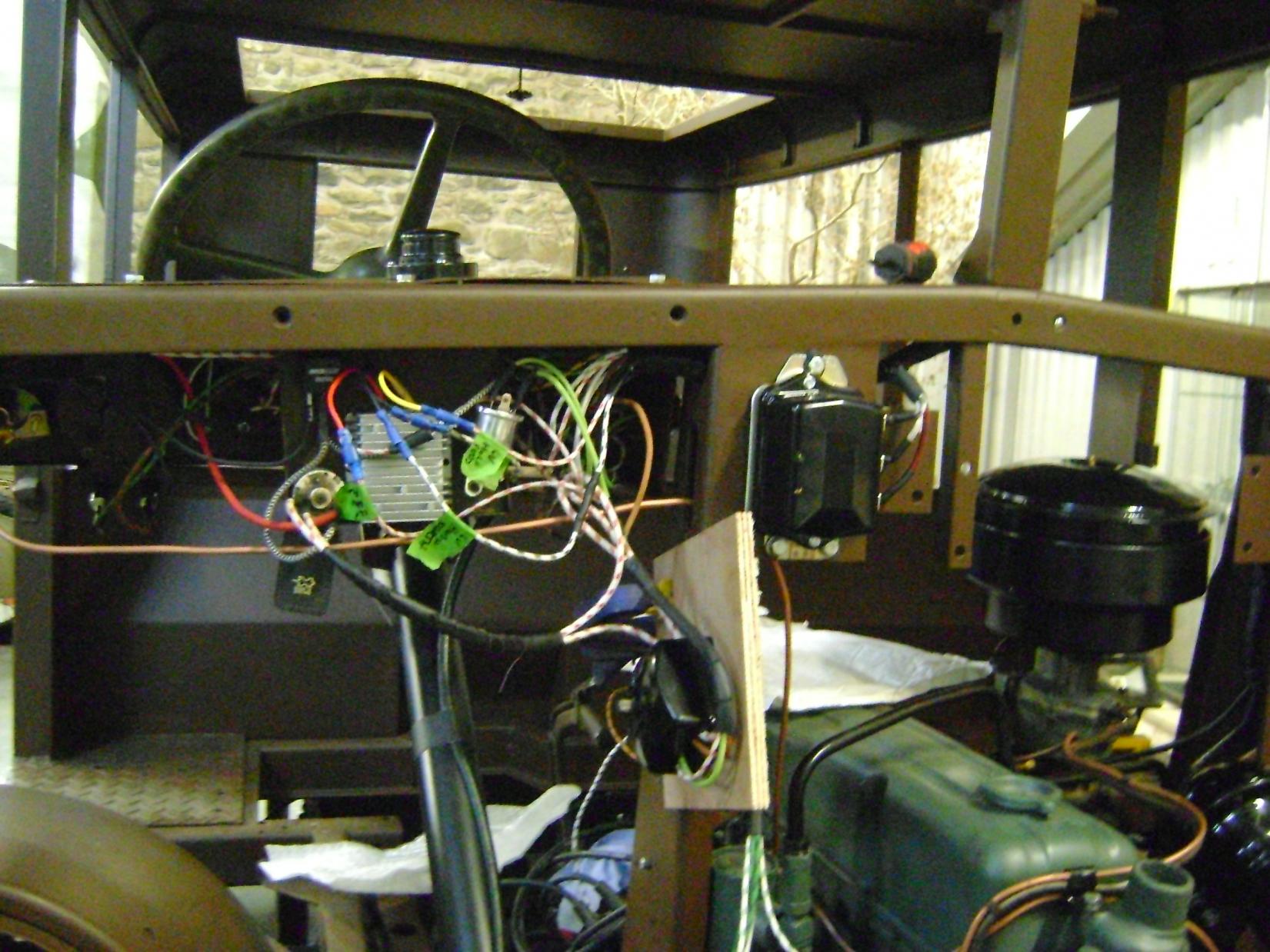
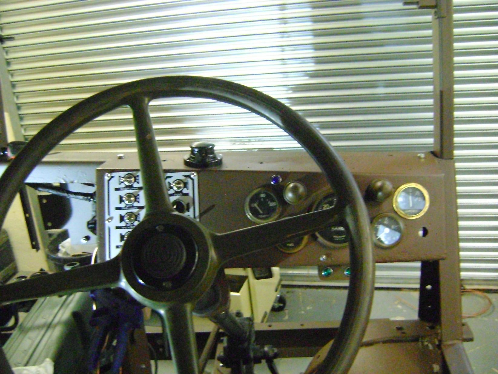
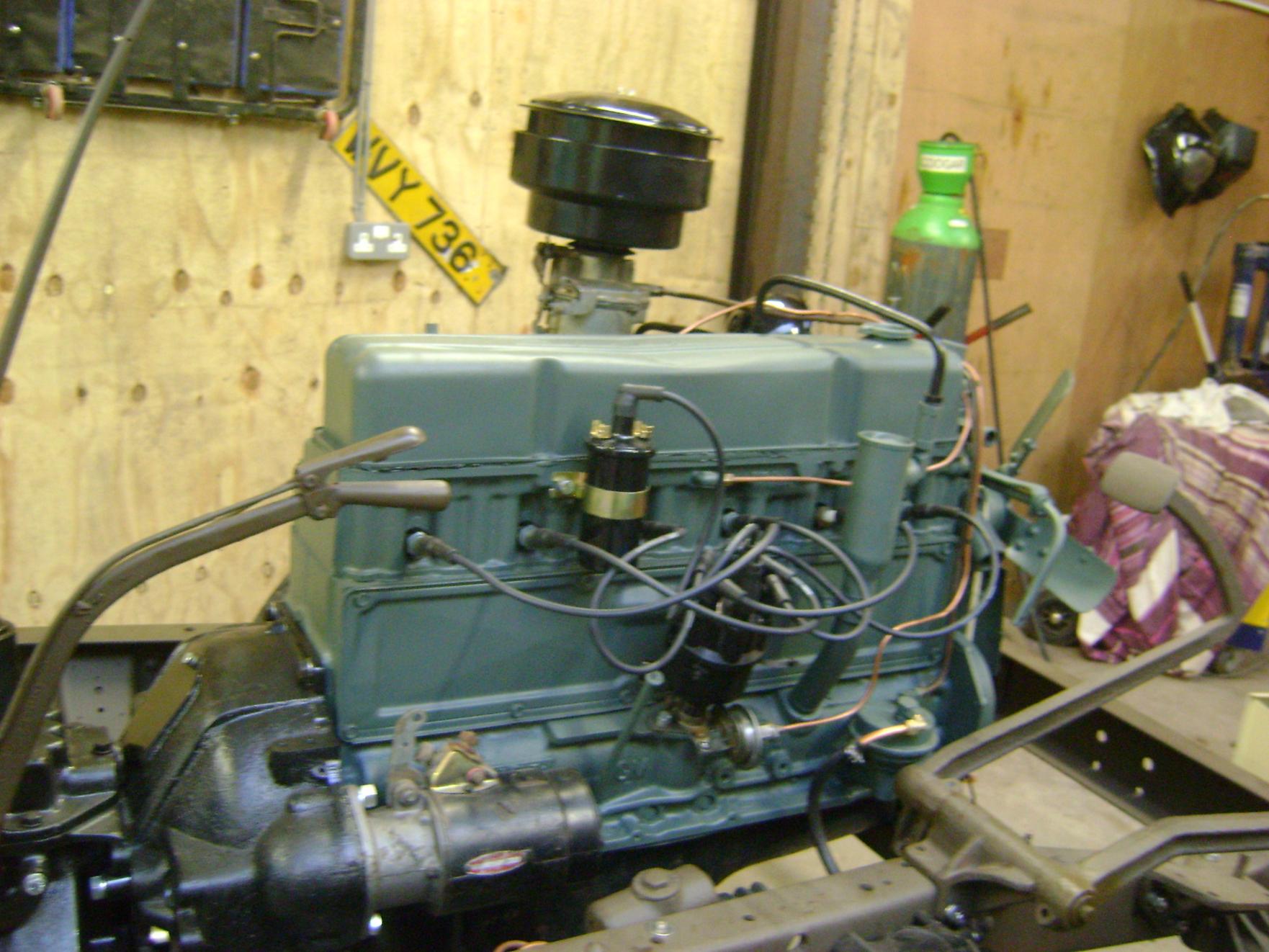
Progress has been a bit slow but its coming. I have been working on the wiring, which is complete and working now. Its all done with cotton covered wire and to the wiring diagram but I have added a fuse box. The horrible bit of modern wiring, that will be hidden under the steering wheel, is a 12v-6v transformer for the horn. I have connected it with blue connectors so that I can't get the 6v and 12v systems mixed up in the future.
Jon


-
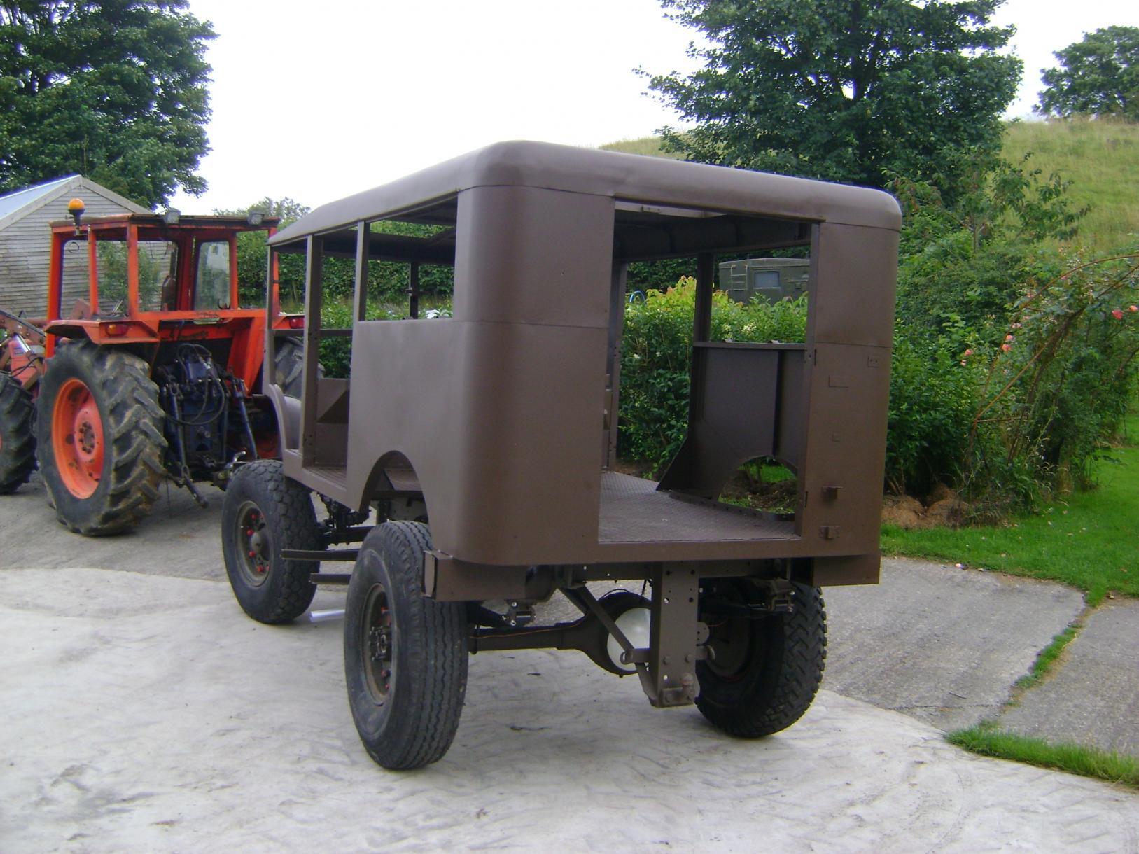
Old friends reunited.


-
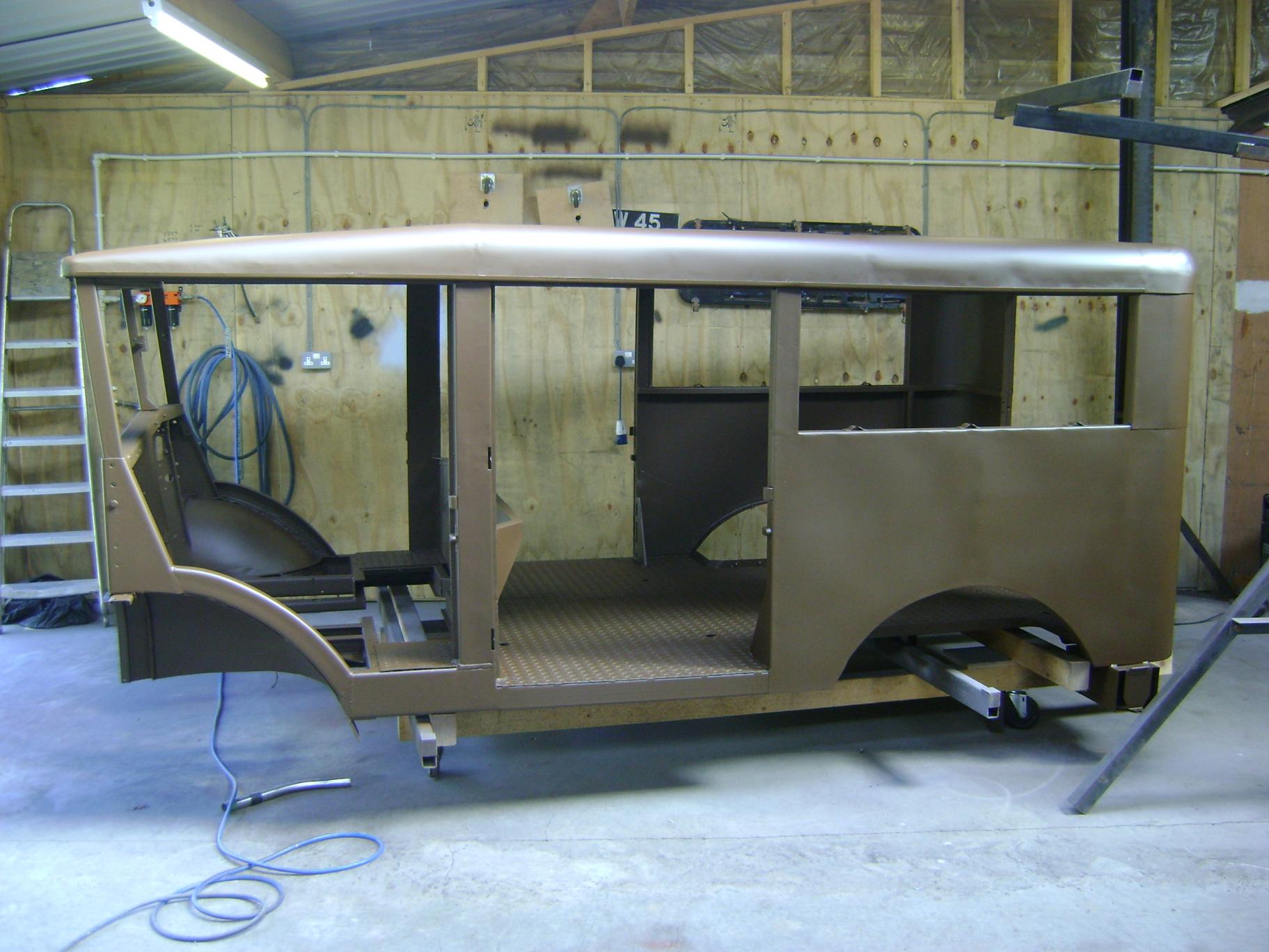
Body in Brown


-
I have been busy today repairing the front inner Wheel arches. Next job, lift the body in the air and spray underneath.
Jonathan


-
Its worth saving and is indeed, in good condition. I don't intend to let it rot but you never know what will appear as the next project and there is always a next project.
Jonathan
-
The radio body was being used by my son as his Army base but he is getting a little too old for that now. Its not worth me trying to tell you the state of this vehicle when I got it, bodged would be putting it nicely. The chassis had been lengthened by 18" and I wouldn't have driven it on the road. Anyway looking at the standard of the work it wasn't modified in its military service.
Regards,
Jonathan
-
Hanno,
thanks for posting the picture on Maple Leaf, I will try and keep it up to date from now on.
Regards,
Jonathan
-
I suppose that you are right but a lot of vehicle restorations are, in reality, just that but to a greater or lesser degree. If I had managed to find all the components needed and bolted them together, would that be any different, it still wouldn't have been a totally "original" vehicle. They are not making them any more, so we have to preserve what we have.
Jonathan
-
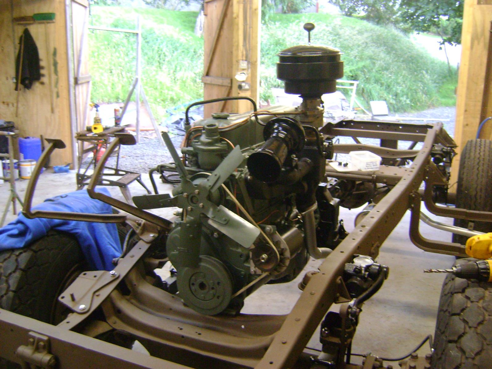
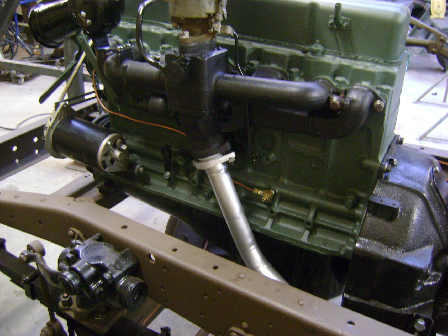
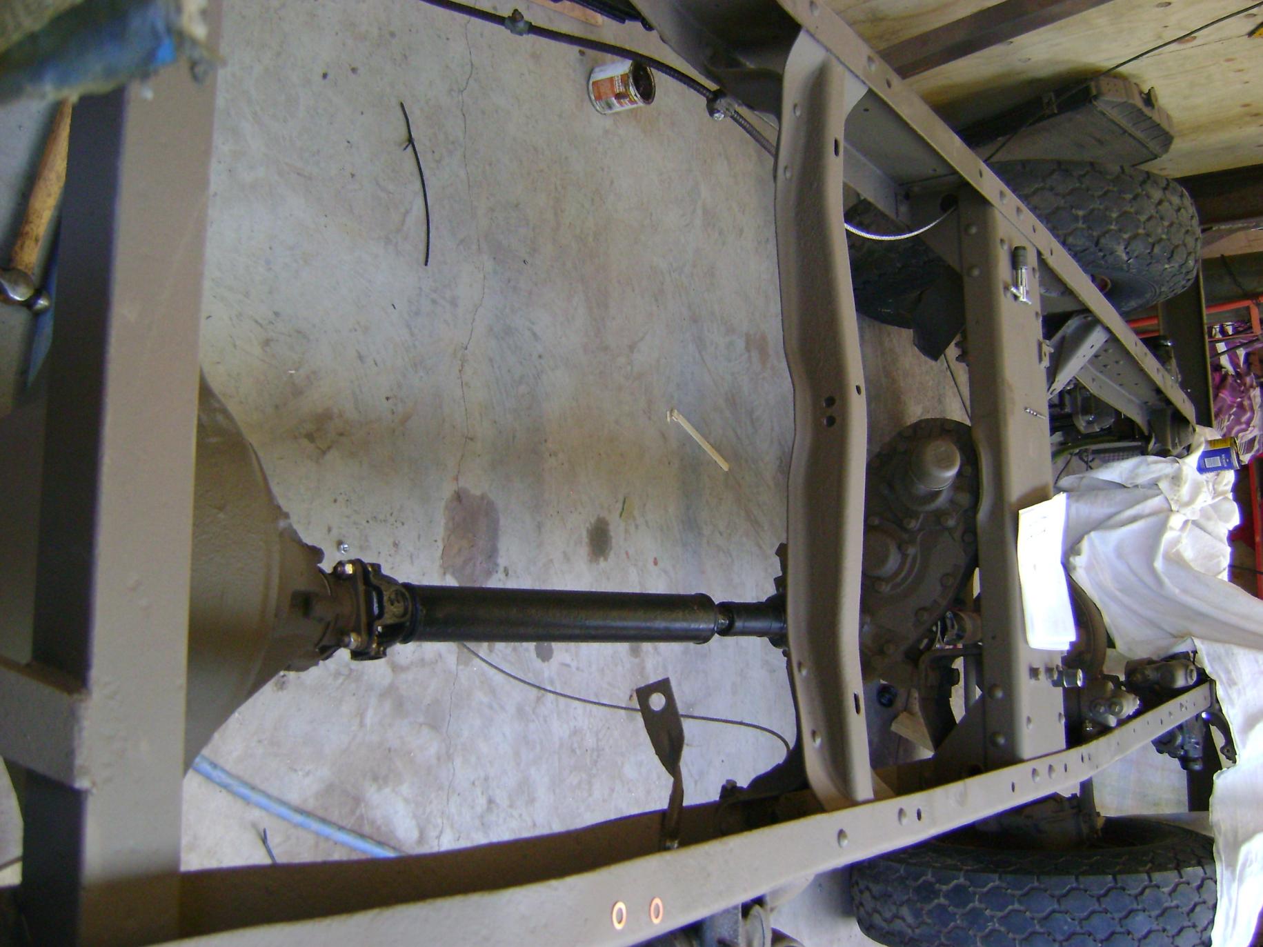
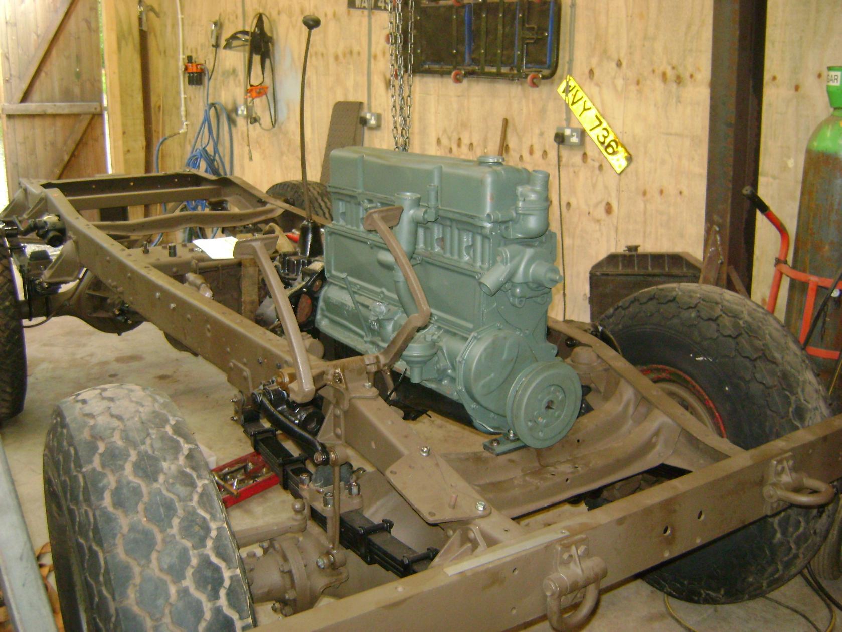
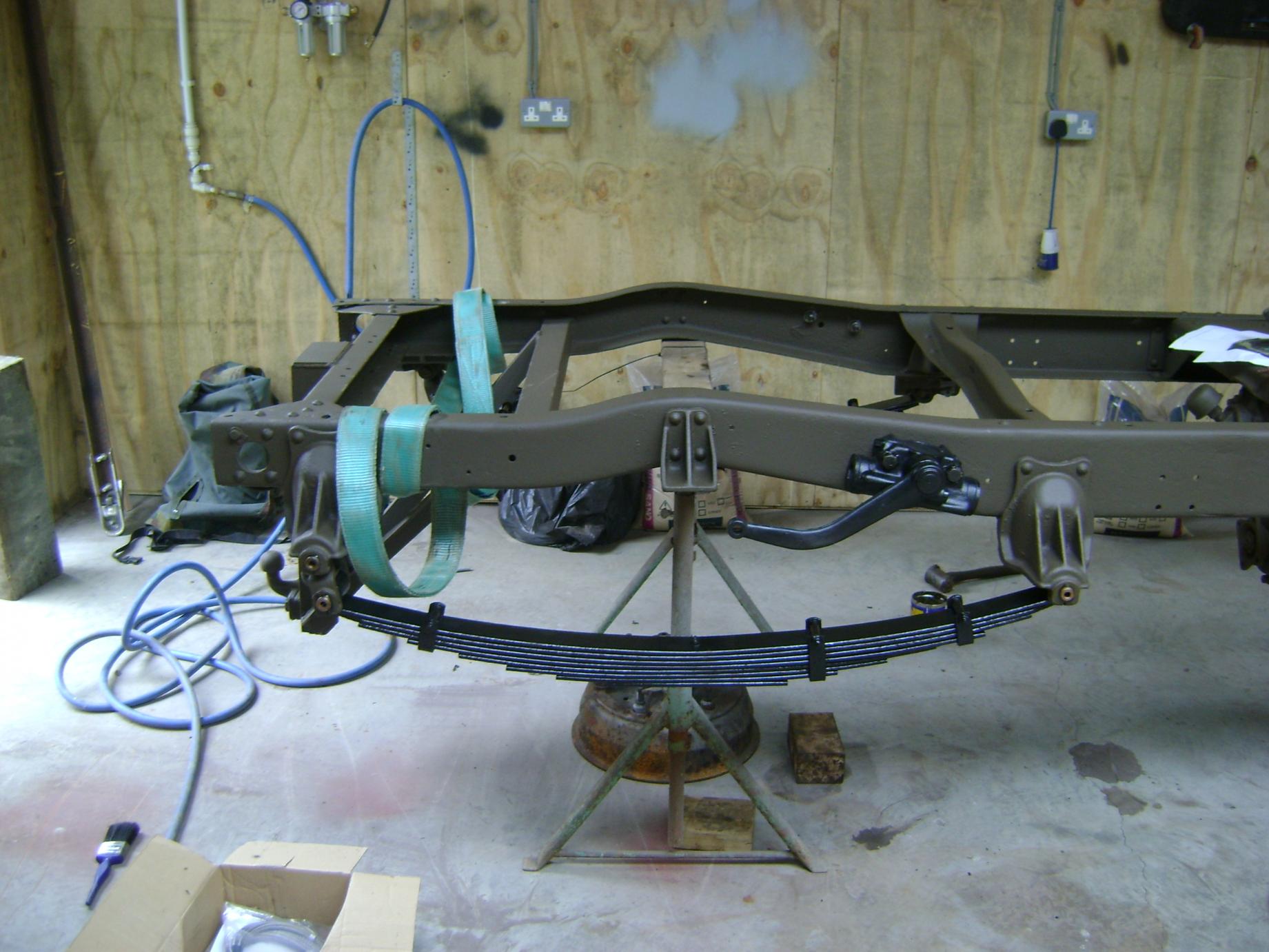
Progress, progress, progress, slowly but surly. All the ancillaries are now on the engine, its all piped up and I have made the exhaust system. I had a box for the exhaust, that I bought when I first got the vehicle, so only needed the bends. As do other people who renovate things, I have lots of bits and pieces lying around, left overs from other projects. So searching through my treasure, I found the front pipe from a series 2a Land Rover Diesel, the right diameter but obviously it needed cutting and welding to suit the CMP, it contains most of the bends needed apart from a 90 deg and a short section of straight. A coat of heat resistant silver and finished. The Chassis is now ready to go in to storage while I finish the body, easier said than done!


-
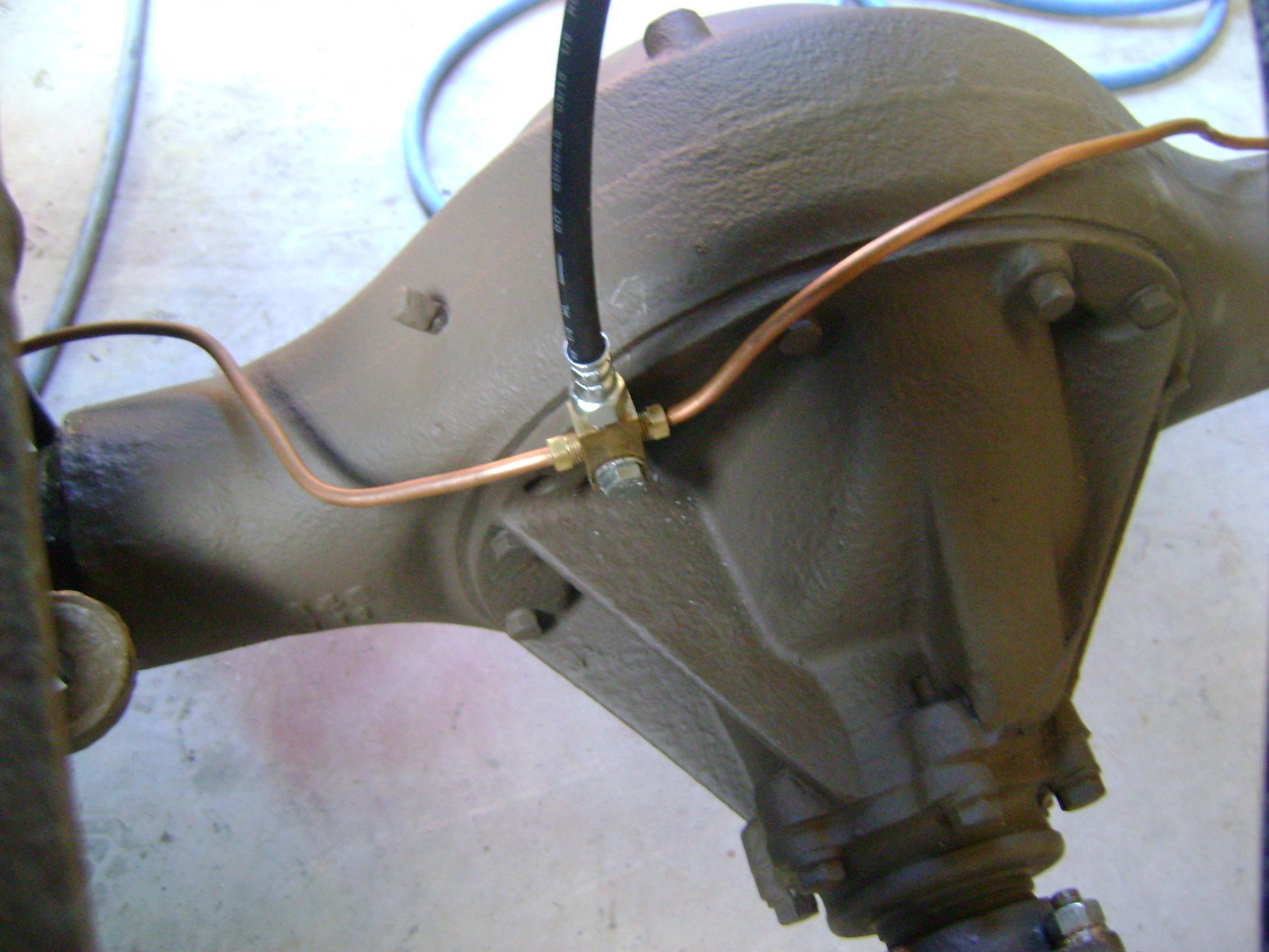
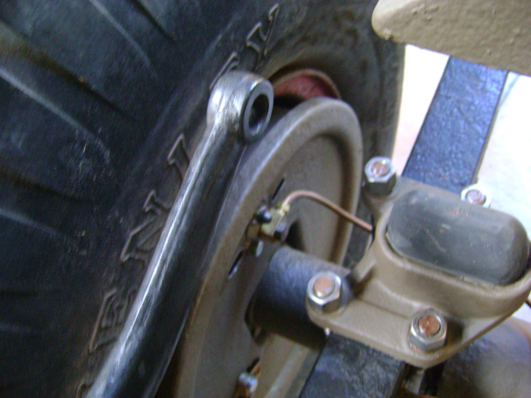
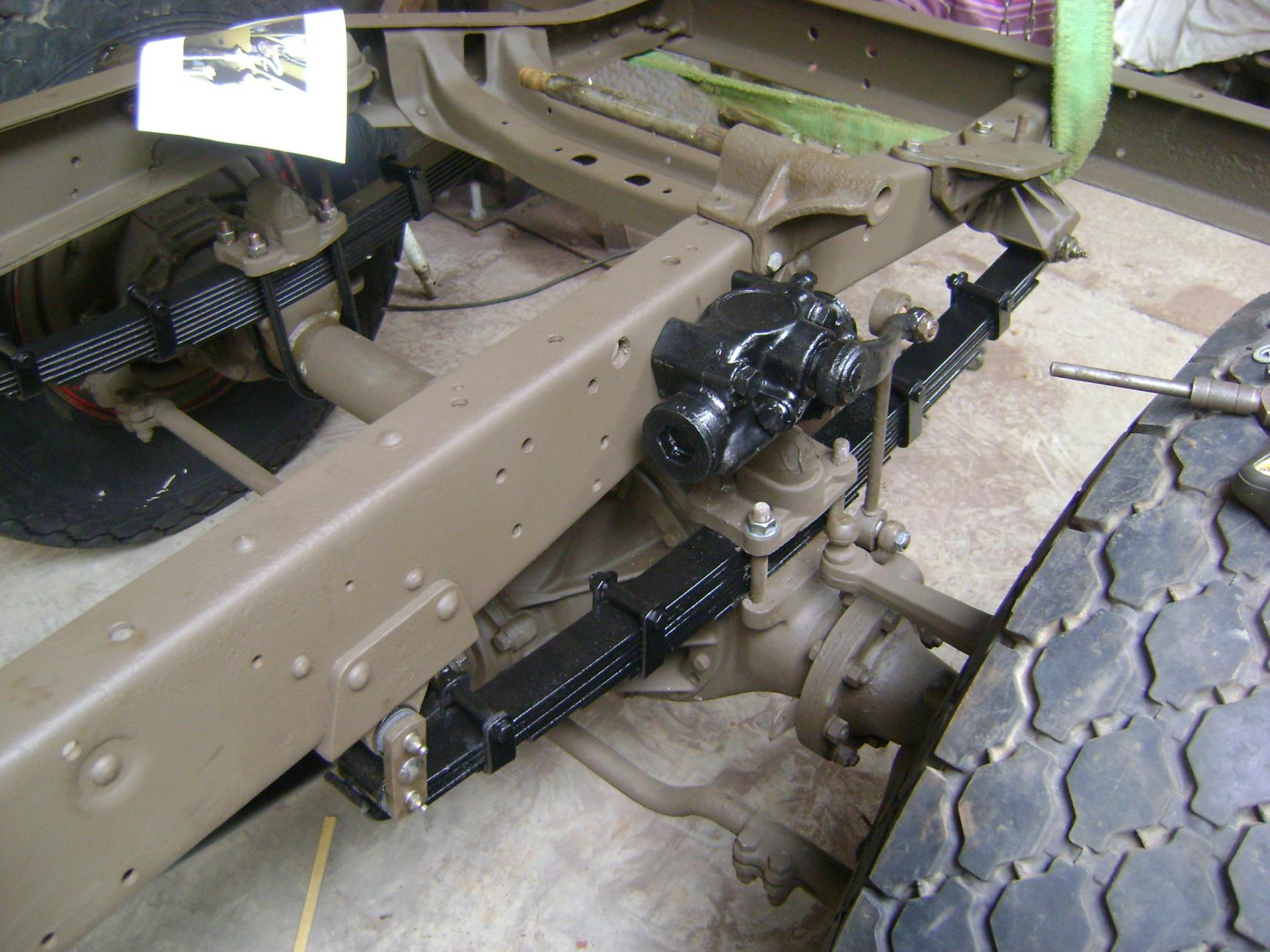
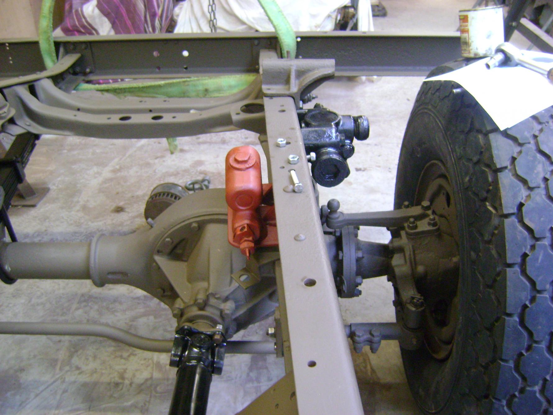
I had time on Sunday to pipe the brakes in. The brake hoses that were on the vehicle, were far too long, infact, the front axle to swivel housing hoses, rubbed on the inside of the wheels. After a bit of research I found a company in Southhampton Hampshire, that had the correct hoses, run by a very helpful chap called Steve.
STAR Automotive
02380849311
Front axle to Swivel housing - NAPA part Number 4900 or his invoice UP4900
Front and rear chassis to axle - NAPA part Number 4960 or his invoice UP4960


-
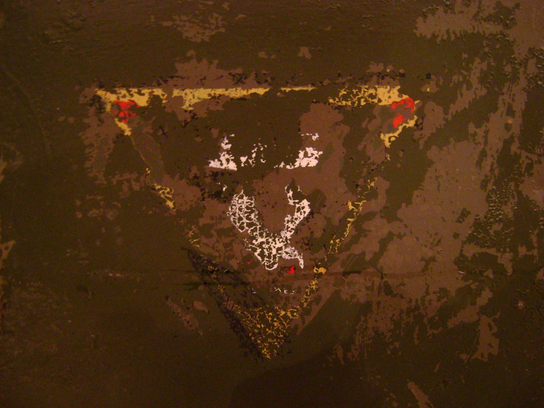
. Thanks for the information Adrian, unfortunately of fortunately depending on how you see it the panel in question was suffering from the old rust bug around the edges so had t be cut out and replaced. That means rather than covering the bull up with new paint I can frame it and put it on the wall.
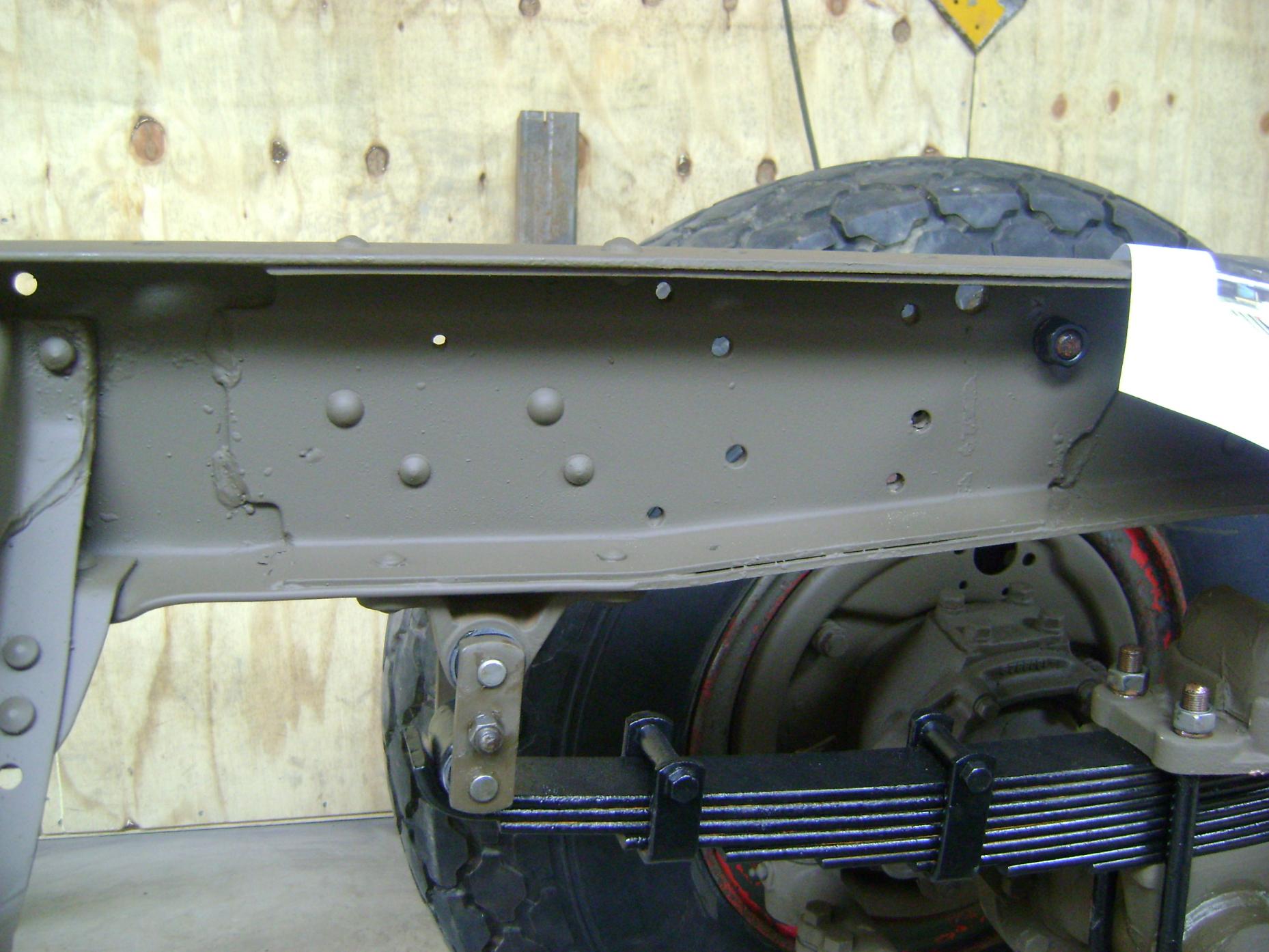
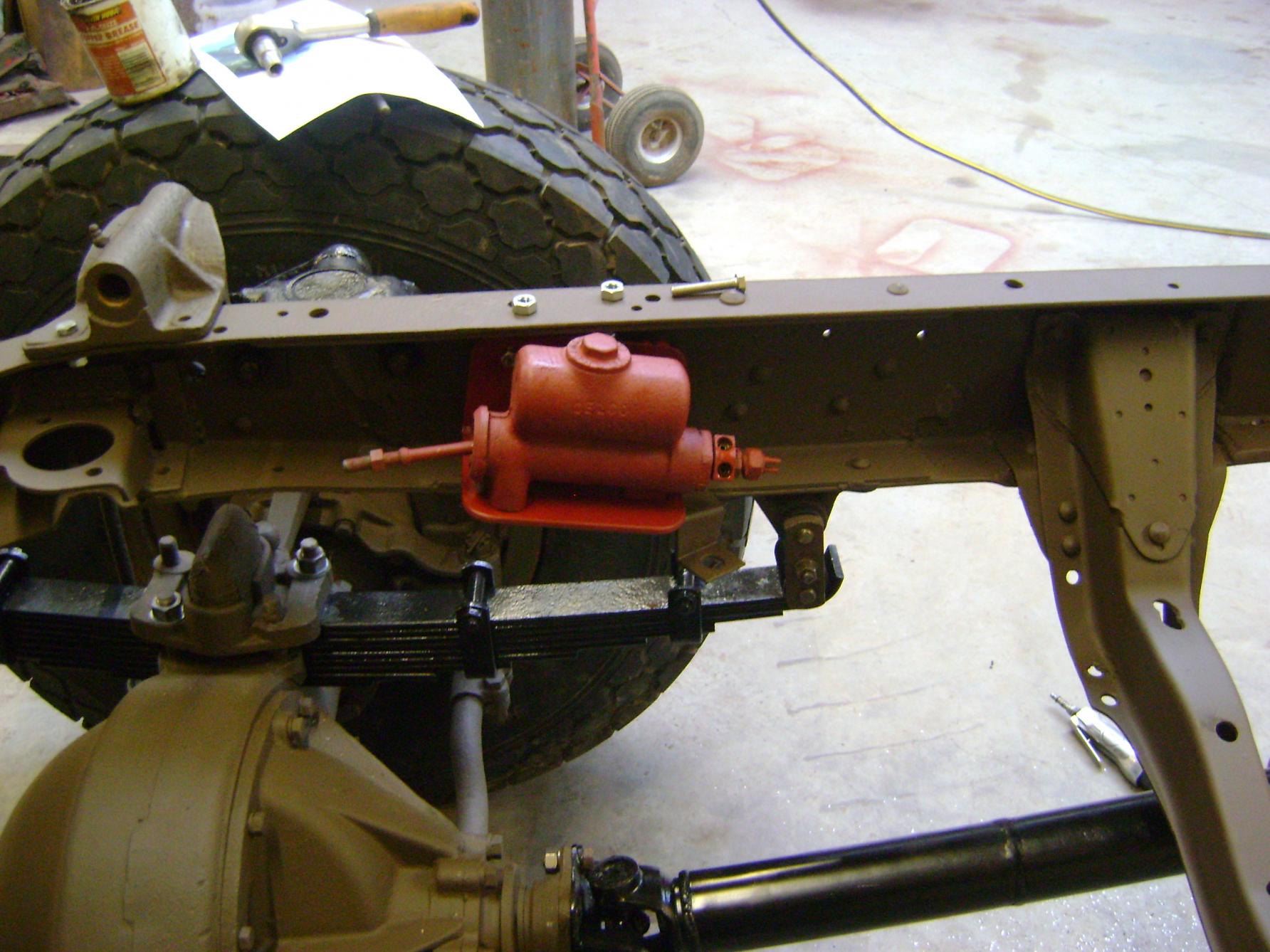
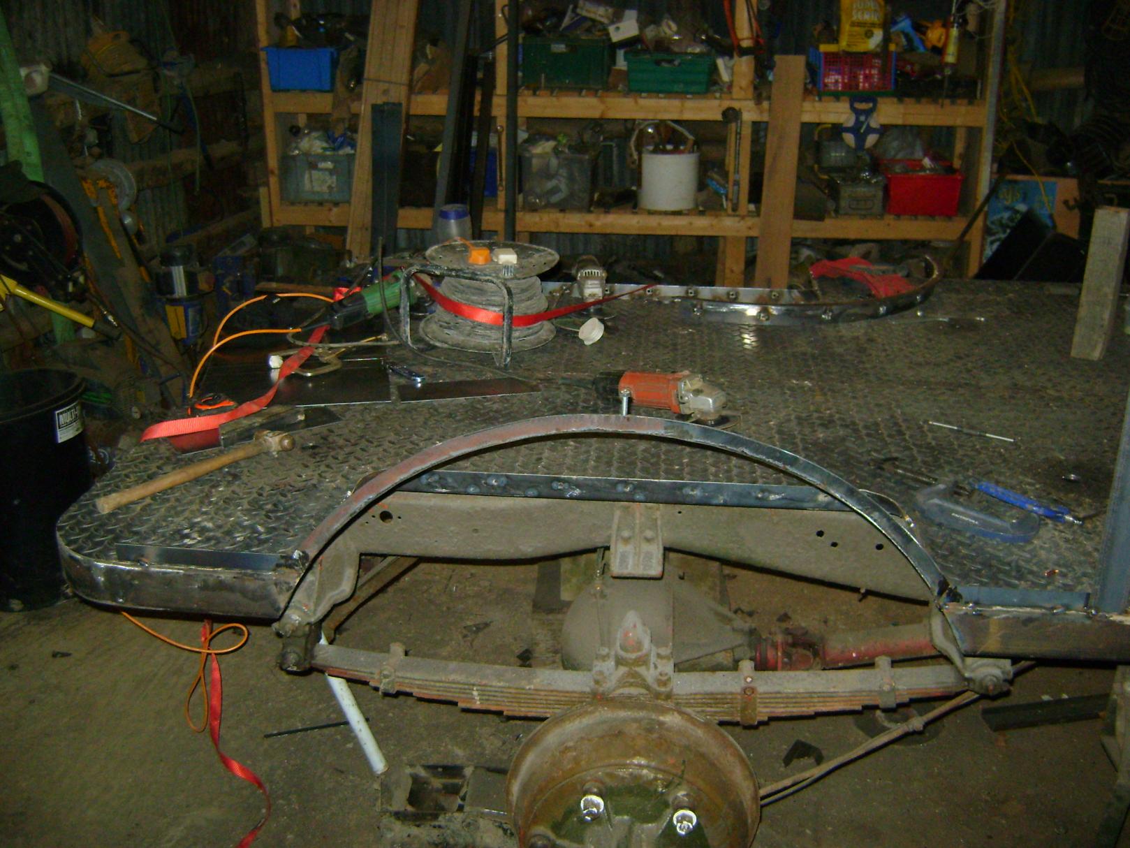
All of the parts that I have been waiting for have turned up so I was able to get the rear axle in and the brakes installed. It took quite a lot of searching to find some of the components so I will post where the parts came from.
Rear brake cylinders - Ebay
Drum Brake Wheel Cylinder-Professional Grade Front Raybestos WC3406( 161726933472 )
Rear spring u bolts and long nuts - ATS springs www.ATSsprings.com (USA) 9/16X3-5/8X9-1/2\" ROUND U BOLT KIT x 2 sets
Front brake cylinders - Ebay
Drum Brake Wheel Cylinder Dorman W4571 fits 40-47 Ford 1 Ton Pickup( 281439639223 )
I hope that helps someone.
Johann


-
I wonder, would they have had the Bull.

-
Markings found under about 6 layers of paint, either side of the bonnet. Original? What do you all think?


-
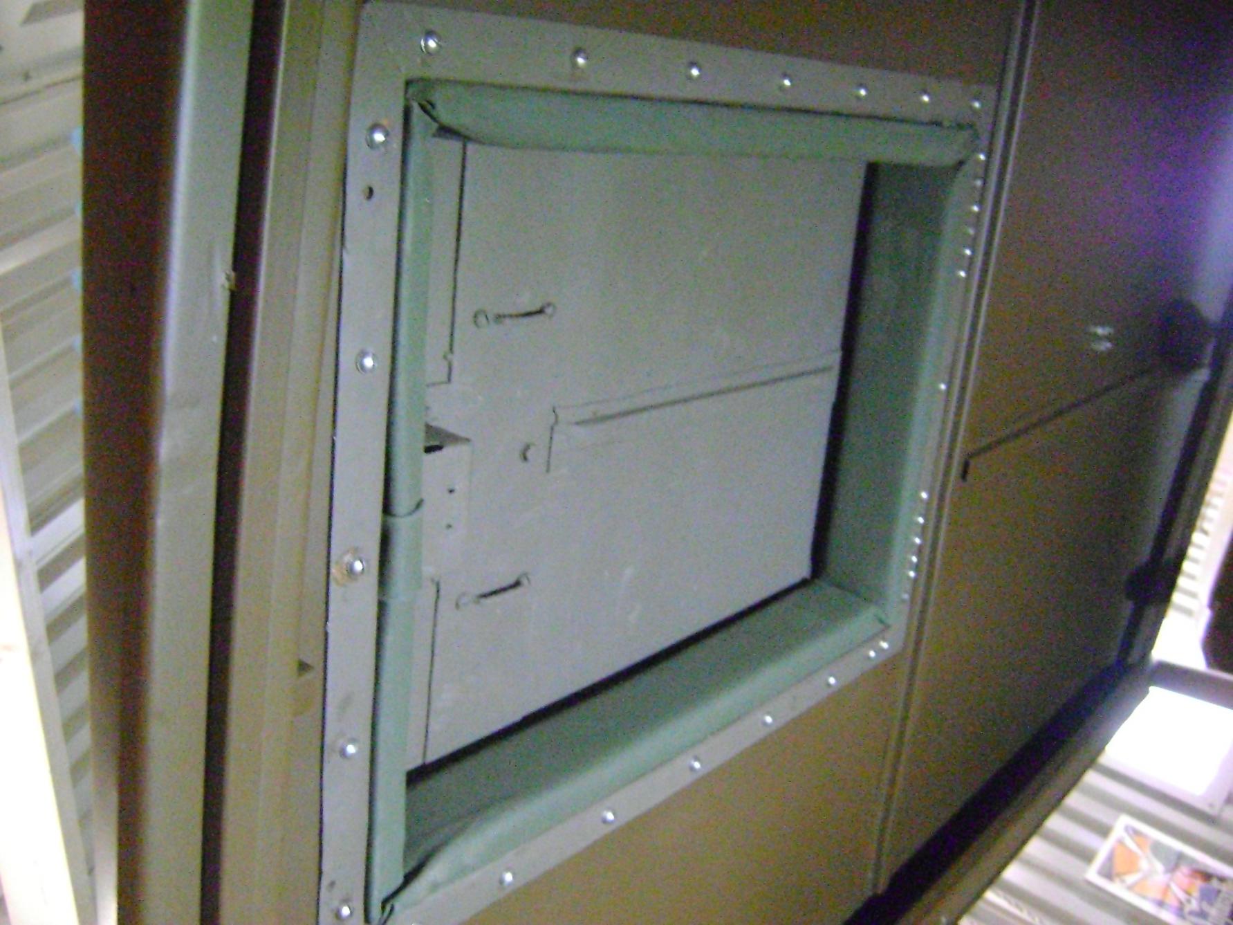
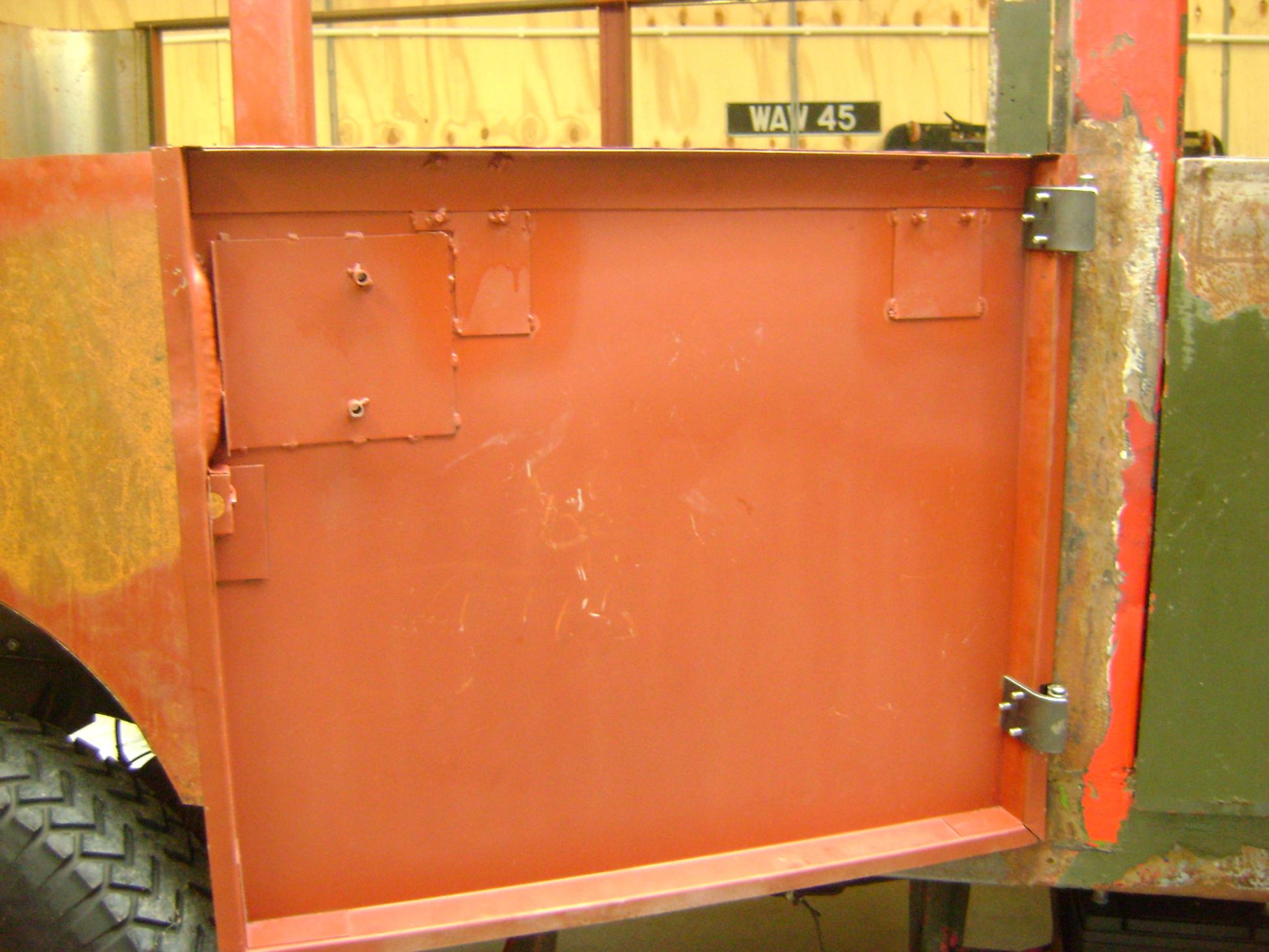
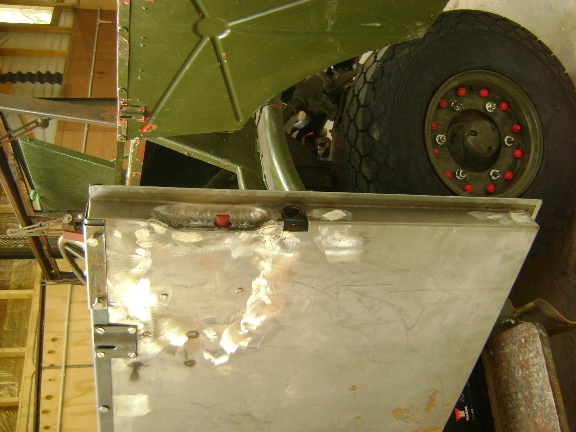
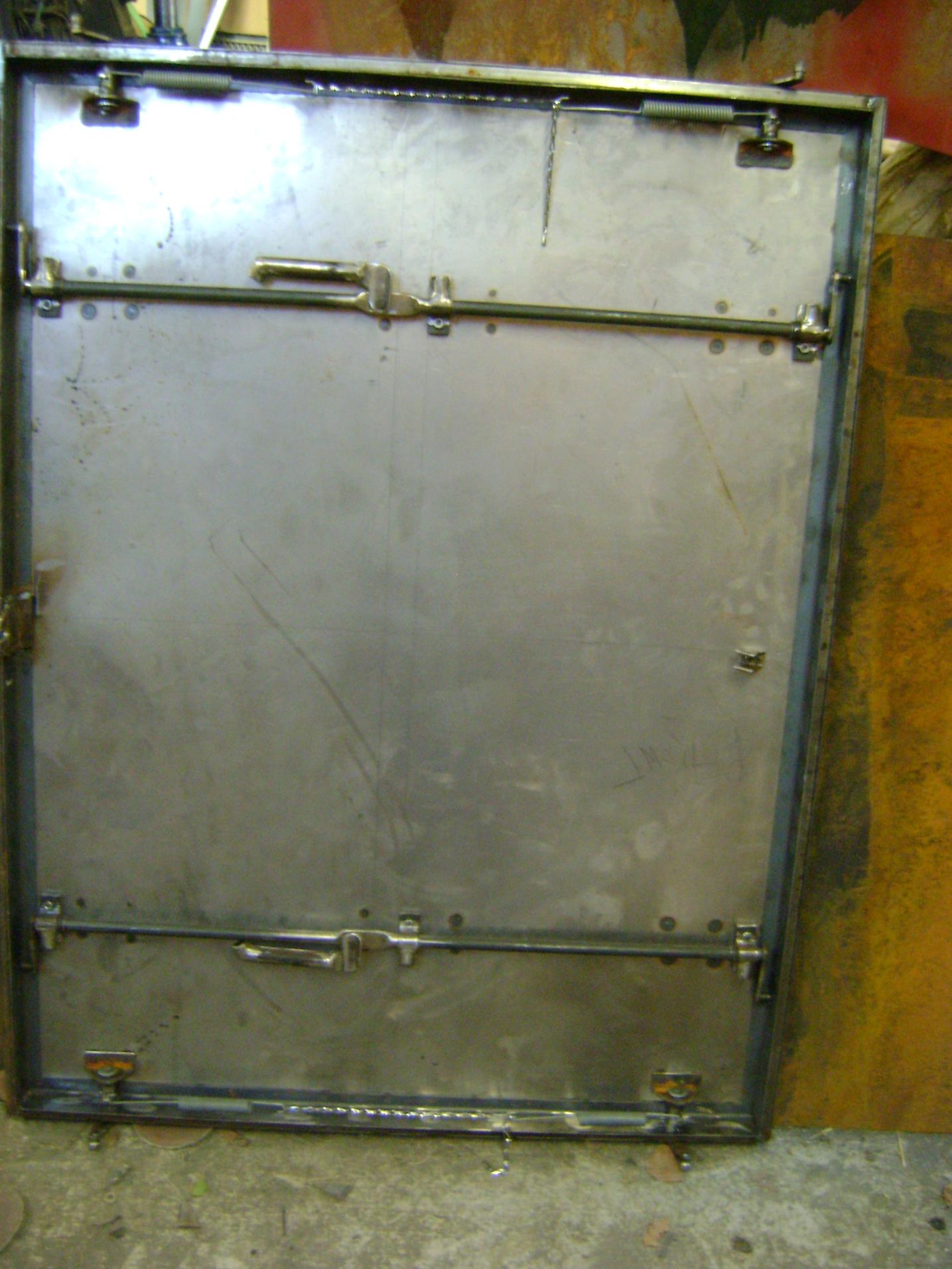
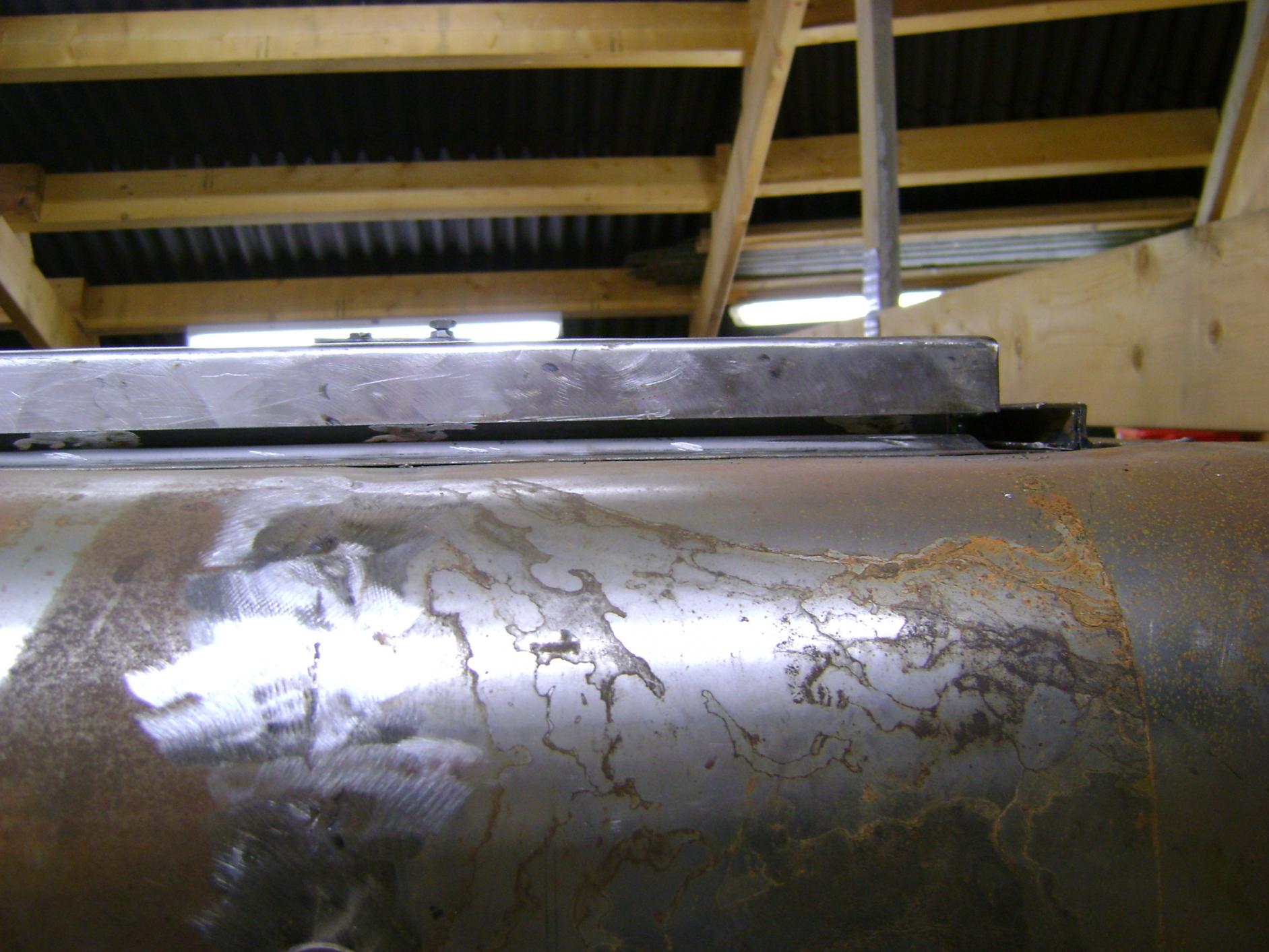
part 3. More home made parts. The door mechanism is an original against my home made version.
Anyone got any wheel split rims for sale? to fit 900 x 16 tyres either 6 hole cmp 13 cab or 8 Hole Morris.


-
Latest part 2


-
I know its been a long time but.........


-
No problem. I love ark welding but I have to admit mig is cleaner. I look forward to the next instalment.
Jonathan
-
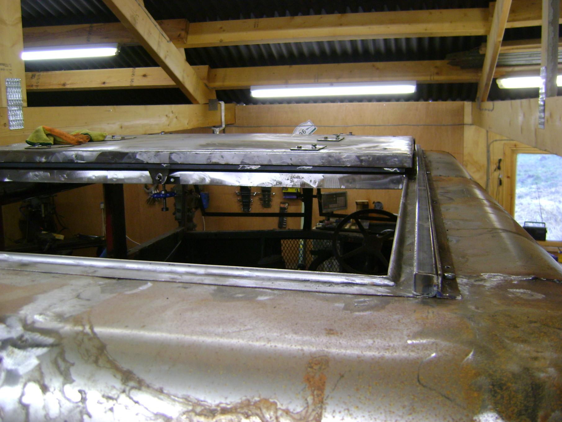
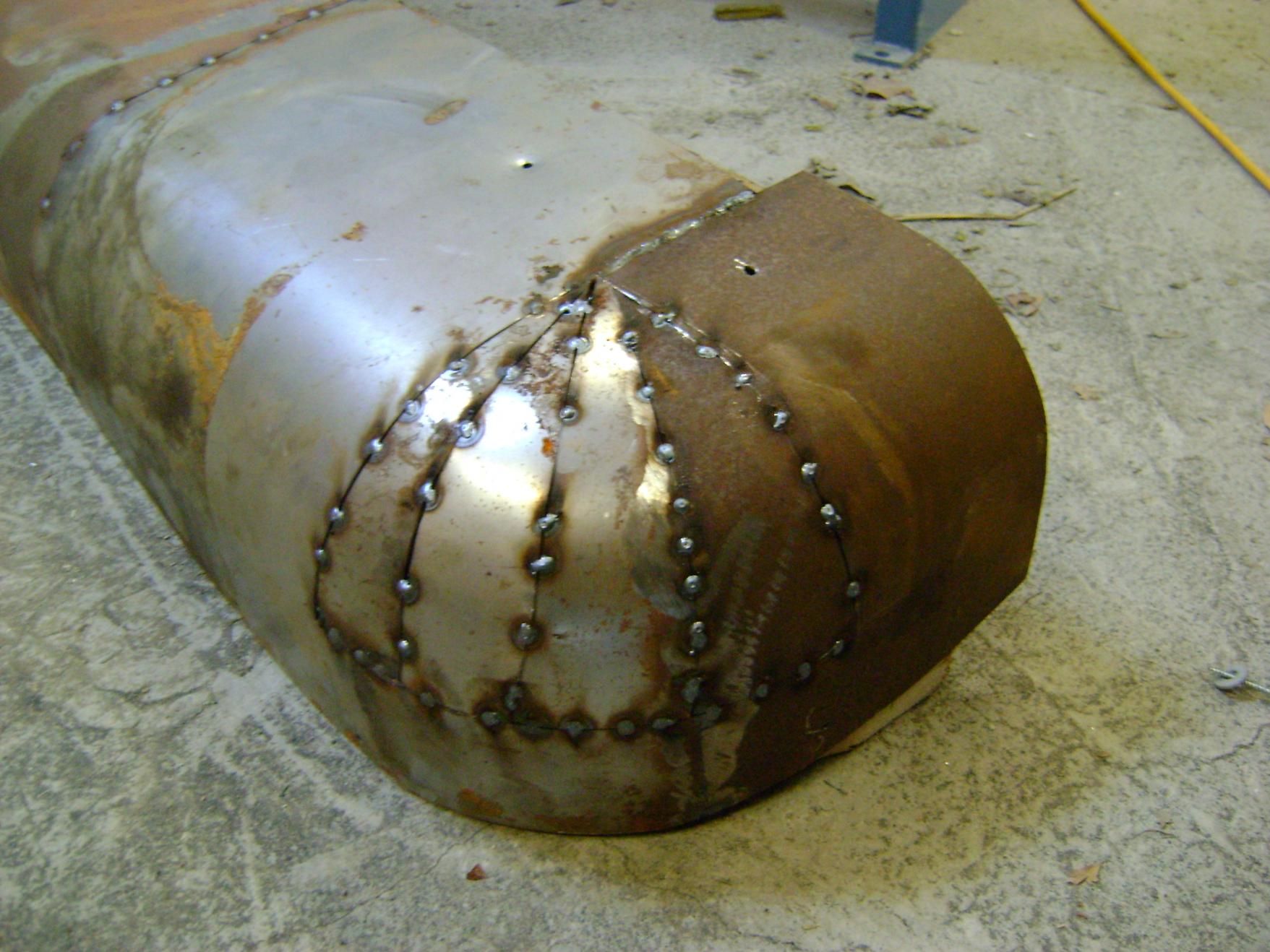
No, not at all, short welds on a low heat and let the glow fade for a second between each weld. Once you get used to it, you get quicker all the time, the trick is don't rush. The roof sheet is 0.8 thick and I use a standard mig, no doubt a tig would be even better but I don't own one. The wheel arches are 1.6mm thick so welding isn't a problem, the mould just has to be solid enough to put up with the hammering of the sections into shape. Once I had made a mould, I had a play with some card to see roughly how the steel would have to be cut and went from there. You don't have to be exact with the initial steel shape, as you progress to form the shape you find that some areas overlap. so using a thin cutting disc cut both layers at once, you get a perfect join then just tack it and carry on. Once you have the shape weld it all up. I hope that helps, I use this technique all the time so I hope it helps.
Jonathan
-
![DSC02335[1].jpg](//hmvforum.s3.amazonaws.com/monthly_2015_10/59dce94f8dec4_DSC023351.jpg.867d8670a8bbd00f922873d185c59ccb.jpg)
Hi,
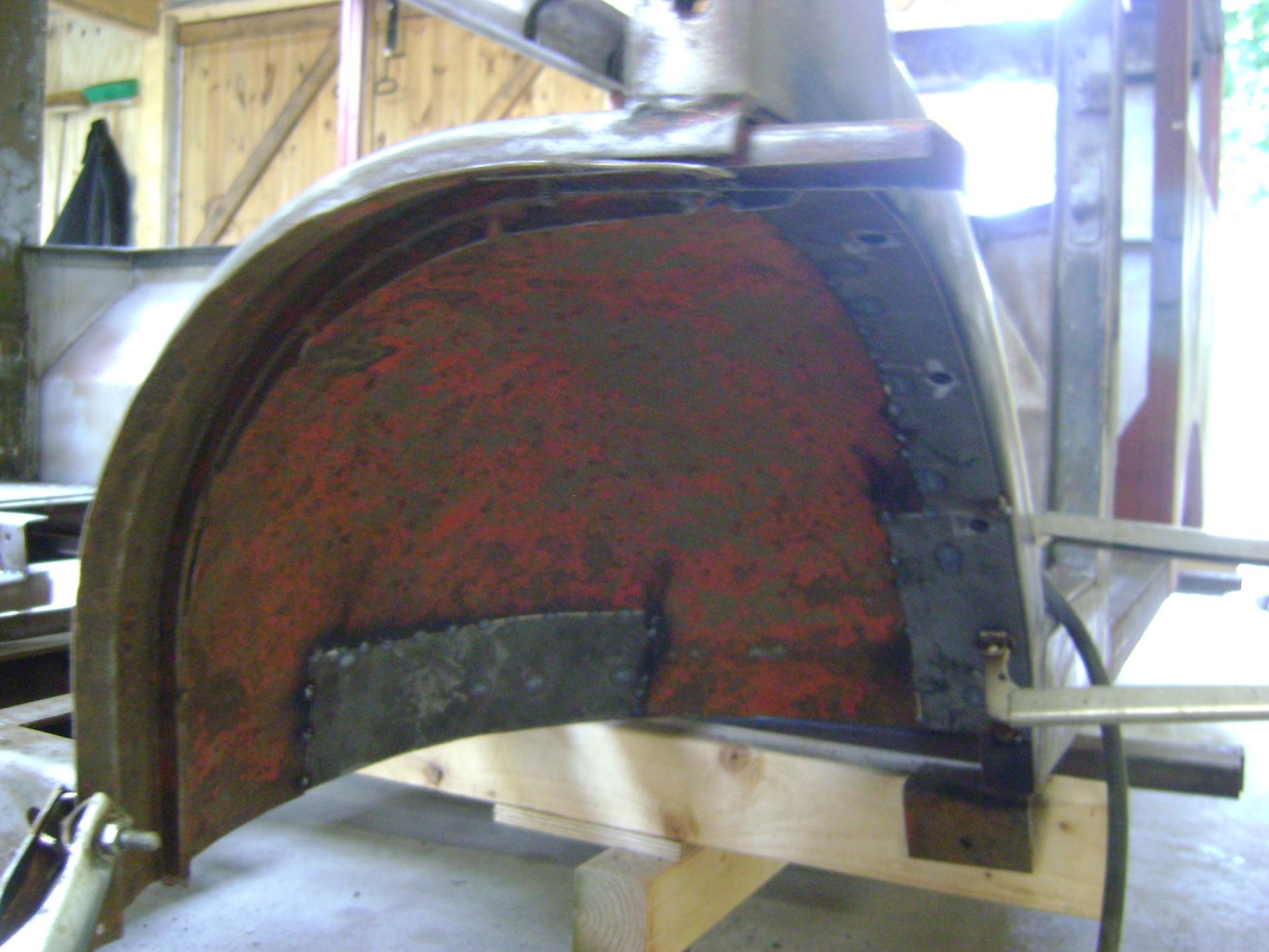
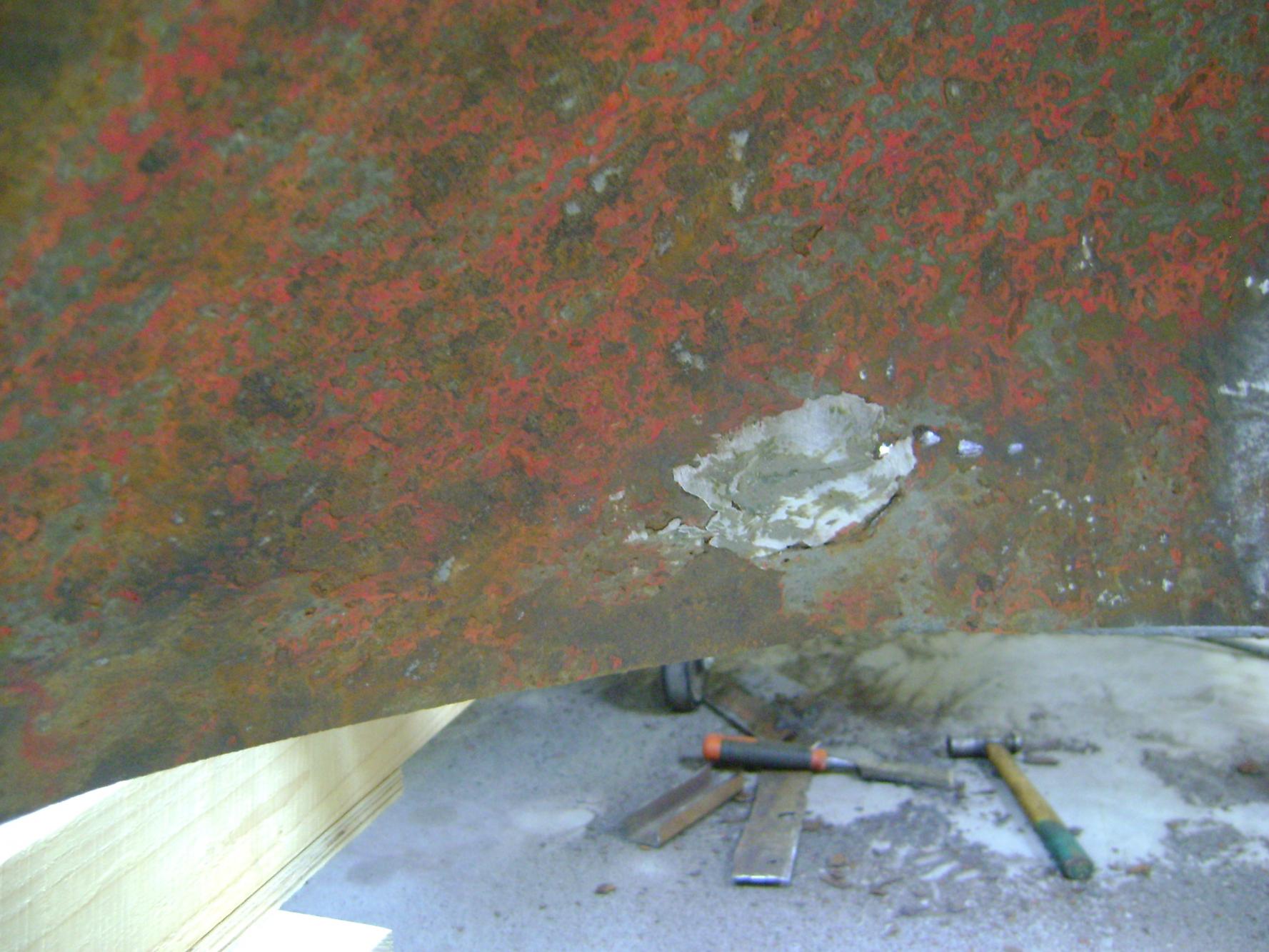
You have done a fantastic job so far, an inspiration to us all. As for the compound curves, I had the same sort of problem with my CMP HUP. The rear of the roof is quite difficult to manufacture, as are the inner and outer rear wheel arches. As the vehicle didn't come with the roof or the rear wheel arches these had to be made. I cant afford to pay someone to do this work and if I could I would prefer the challenge myself, I don't the access to the pressing or forming equipment either so fabrication, cutting and welding, was the only option. As you can see from the above picture I used wooden moulds, this isn't practicle for more then about two off but for small quantities it works well. I am pleased with the end result, its a cheap and a fairly easy method, although it does mean a lot of cutting and grinding. Carry on the good work.
Jonathan


![DSC02327[1].jpg](//hmvforum.s3.amazonaws.com/monthly_2015_10/59dce94eedae3_DSC023271.jpg.ac914da58a0944ff0792fcb631ce0fa9.jpg)
![DSC02329[1].jpg](//hmvforum.s3.amazonaws.com/monthly_2015_10/59dce94f2888c_DSC023291.jpg.eef1654e0785f0c5ca466249dc64bb81.jpg)
![DSC02334[1].jpg](//hmvforum.s3.amazonaws.com/monthly_2015_10/59dce94f60f29_DSC023341.jpg.578359dd032a1eb5d953ad5ba22bd63e.jpg)
-
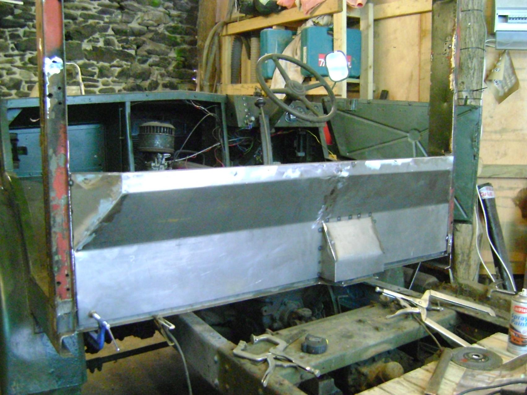
Hello,
I bought the vehicle in about 2013, its been around the block and has featured on this site before, so some will recognise it. I did quite a bit of work on it, converting it back to a HUP but then other things interfered and I had to leave the project parked to one side. I am at a point where I can at last pick up where I left off and I thought that you might be interested. I have added some pictures to be going on with but I will add a more detail later. Anyway I hope that you like what you see.
Jon:cry:


![DSC02335[1].jpg](http://hmvforum.s3.amazonaws.com/monthly_2015_10/59dce94f8dec4_DSC023351.jpg.867d8670a8bbd00f922873d185c59ccb.jpg)


![DSC02327[1].jpg](http://hmvforum.s3.amazonaws.com/monthly_2015_10/59dce94eedae3_DSC023271.jpg.ac914da58a0944ff0792fcb631ce0fa9.jpg)
![DSC02329[1].jpg](http://hmvforum.s3.amazonaws.com/monthly_2015_10/59dce94f2888c_DSC023291.jpg.eef1654e0785f0c5ca466249dc64bb81.jpg)
![DSC02334[1].jpg](http://hmvforum.s3.amazonaws.com/monthly_2015_10/59dce94f60f29_DSC023341.jpg.578359dd032a1eb5d953ad5ba22bd63e.jpg)


New addition Bedford QL
in British Vehicles
Posted
Thanks Richard, I will check in the morning. The number above the QL numbers appears to be D/109, the new log book states the chassis number as QLD10936809 but the old brown log book states D/109. QLD's don't have winches, do they?
Jonathan