


mattinker
-
Posts
59 -
Joined
-
Last visited
Content Type
Profiles
Forums
Gallery
Blogs
Events
Articles
Store
Downloads
Posts posted by mattinker
-
-
A word of encouragement! I've been following you for years, first the Denis and now the Thorny.
I saw you in Brighton with the Denis, but, I won't be able to make it this time. The best of luck!
Thank you! Regards, Matthew
-
15 hours ago, Old Bill said:
Right there Doug! The trouble with this hobby is that each project requires a breadth of knowledge and I am rather lacking in depth. It is great to have so many people with so much knowledge that they are prepared to share. Thank you very much!
Painting would be our real bottleneck if it wasn't for Dad. He is doing some every day and trying to get ahead
of the game by painting all the planks before assembly. This will inevitably mean that some touching up is required but also that there is paint in all the joints so water trapping should be reduced. As space is so limited, the lorry is also used as the painting bench!

The last time I was down, I fitted the oil pressure gauge pipe. This has no obvious routing so I have run the tube underneath the engine, across the chassis and up the gauge on the rhs. A couple hours with the pipe bender produced this:


Then I had to get it into the chassis and connect it. The main oil lines are 1/2" and 3/8" and I could not attach my 1/4" line to the fittng. To get over this, I cut a short length of 3/8" tube, flared it, sleeved it and then silver soldered it onto the 1/4" .

Seems to work but my arms weren't long enough to blow down one end with myfinger over the other to test for leaks!

Final installation.

It is straighter than it looks,. That is an optical illusion!
Steve
")
Hi Steve,
I haven't posted in a while, but I've been following along! Enjoying it as much as ever.
With this kind of capillary tube oil pressure gauge, it is customary to include a couple of coils to render the pipe more more flexible. Engine vibration quickly work hardens copper, I'm afraid that without coils, you're running the risk of a broken oil pressure pipe!
Regards, Matthew
-
I agree with you up to here.
I don't see that this can be a "work hardening" problem as I understand the term. I would rather expect it to be possible to bend the material into shape shown by cold-forming without fracture, if it was possible to apply the loads required to achieve that. It isn't a very large shape change.
Andy,
Properly forged, (Sorry Steve!) it would have been possible to open up the bend a little bit without cracking, had it been hardened any form of carbon steel would have broken not cracked.
Regards, Matthew.
-
T Heating the steel for a long period in a carbon rich environment is bound to cause that and my quenching made it glass hard. I should have heard the warning bell when I tried to drill it as that certainly took some doing!
What do you actually define as 'cold forging'? Would that be at room temperature or just below red heat? I am a very poor blacksmith so my temperature control is a bit variable but I don't generally hit it unless it is glowing to some degree.
Always something new to learn!
Steve :-)
Steve,
Mild steel is just that, not enough carbon to make harden-able. You would not have been able to introduce enough carbon to make it brittle (otherwise, it would be a known technique for making harden-able steel!). So the only thing left is forging too cold!
Still following along and enjoying the ride! May be see you in Brighton next year! All the best, Matthew.
-
Just a word to say how much I enjoy this thread. Thank you for taking the time and trouble to keep us informed of your progress by recording this interesting restoration!
Regards, Matthew.
-
Just a quick word of encouragement! I know it's nice to know there are people out there following on! Thank you for this great thread!! Regards, Matthew.
-
It is perfectly feasible to drill square holes using a rotary broach. The attached video is for drilling hex holes, but a square, hole is done using a square tool!
Regards Matthew
-
Thanks Matt. I'm glad you haven't got bored with it yet! Perhaps we will meet on Brighton seafront again next year. We are hoping for nine Great War vehicles this time so it should be worth seeing!
Steve. :-)
Steve,
I don't know whether or not I'll get across the channel for the next Brighton run, I hope so!
Thanks again, Matthew
-
I don't have much to say apart from how much I enjoy and apreciate your rebuild and the associated thread. Thank you for making all this available.
Thanks again, reegards, Matthew
-
Hi Steve,
You say of the Thorny steering wheel that “It was originally a steel tube rim surrounding a cast steel centre”
Which poses a question; will your new aluminum wheel have the same strength as the original?
John
I don't think there would be a strength problem, the Denis one seems to work. How about a crash test to see! ;-}
Regards, Matthew
-
It's nice to see your back at! looking forward to the Thorny rebuild
Regards, Matthew
-
Nice to see you back at it! I've never seen cast Iron pistons before, all that mass flying backwards and forwards, the mind boggles!
Enjoying the progress as always,
Regards, Matthew
-
Hi Chaindrive,
That coupling looks like it was made of rubberised canvas.
regards, Richard
I would go so far as to say the look like they've been made of old cotton reinforced tyres!
Regards, Matthew.
-
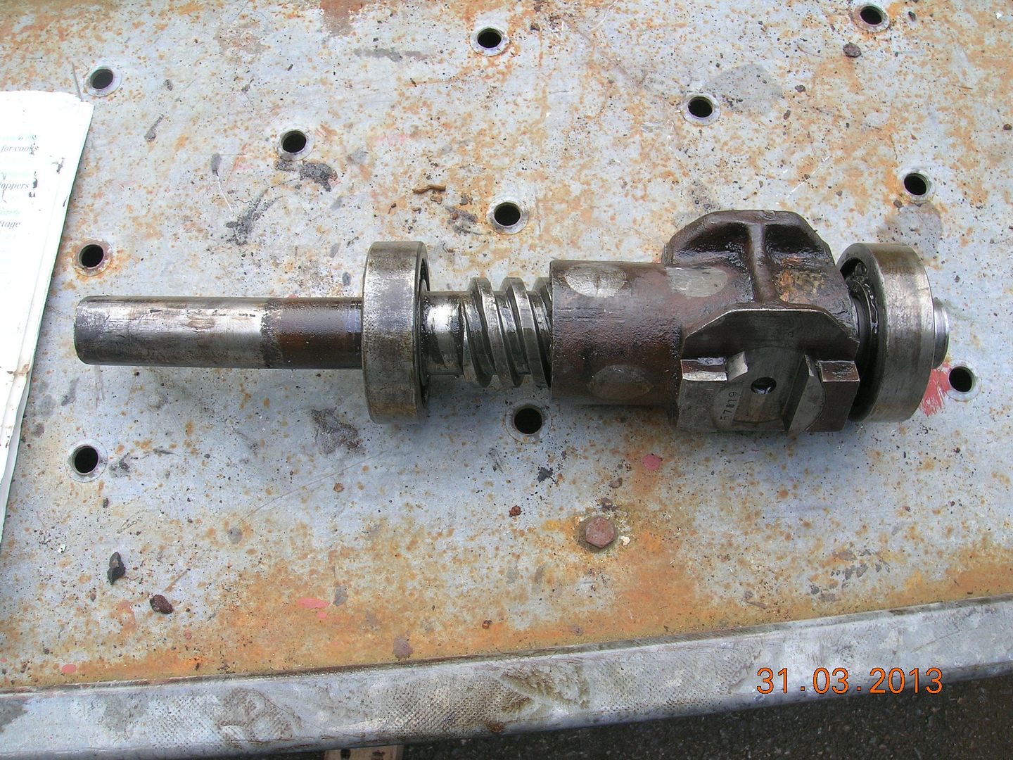
Hi,
The whole thing will become clear when there are holes drilled in leather. The washers go on the leather so that The two forks will be coupled by the leather. Six holes in the leather will be bolted to one of the six holes in the two forks, the forks won't touch each other.
Give me a shout if I'm not clear!
Regards, Matthew
-
I'd be very keen to see all the bits cleaned up. It may be there shims to take out between theouter screw casings.
Regards, Matthew
-
Using the whitemetal approach, I would start y looking at the actual wear. If your good enough with the lath to take the wear out then your in. Have you done a file test on the thread? When making leadscrews for a lathe, you use an unworn part of the lead screw. It would be possible to turn up a dummy shaft. Youtube film on making babit.
Is there a "split line? Babit is usually poured with shims toi to allow for adjustment.Regards, Matthew
-
Notice the big “silver” spots on the steering nut shell. They are of white metal and the whole of the big thread inside the shell is white metal. Goodness knows how this is done but there are “ silver spots” like this on the four sides of the shell. Presumably the white metal is poured in through these holes and the outside of the casing is then cleaned up afterwards. But how is the thread inside made?
The threads would "smoked" with lamp black (acetylene torch burning without Oxygen, or a candle) to stop the white metal sticking. Dams would be made to stop the babbit leaking out and they would be poured in the same way as a smooth babbit bearing. This is a method that is sometimes used to refurbish worn half nuts on old lathes.
Regards, Matthew
-
I would be concerned that the cracking is more extensive than you can see. It is obviously caused by fatigue from the clutch being pulled in and out rather than the torque and if that bit cracked how far behind is the rest? Are you sure it is weldable? I wonder if it is quite a high carbon steel to give an almost spring steel and if so you could be causing more cracks by welding.
David
I agree with David about the cause. I would be very surprised if it is hardened steel. It's after all running in a warm environment! I'm not sure that adding a ring and tacking it on isn't just putting a weakening ring of welds further out. I would suggest, if it "passes" the file test for steel, to avoid deformation, either heat up the whole thing before welding, or weld short lengths and let it cool between welds. You have nice weed burner and I seem to remember a forge!
I think, a good weld repair would be sufficient for your uses!
Just don't blame me if it breaks!
Regards, Matthew
-
Side valve engines have a short valve train therefore 12 thou would seem reasonable as an engine hot clearance. I doubt there is much overlap on this engine, and it won't be too sensitive to valve timing. Try it and see!
Regards, Matthew
-
The star is the non-standard stamp ( the difficult / impossible one to get / forge )
I just thought I'd point out in passing that a star is in fact an easy punch to make, a drill dimple in the middle and filed grooves around the outside, temper and it's done.
Regards, Matthew
-
Hi Matt.
There is no governor adjustment at all so I think it must just have been to protect the engine from inexperienced drivers.
More pictures later. :-)
Great, I always look forward to new pictures!
Regards, Matthew
-
Thinking about it, the governor is fitted to prevent engine overspeed conditions, which may have been more of a concern for stationary engines (e.g. the water pump that ended up in your splendid Dennis) if the load was suddenly removed. That might well explain why there is no butterfly fitted to the truck. (Or not, I suppose.) :-D
I was wondering if the governor wasn't used in convoys? I am assuming that these are governors that can be set to a specific engine speed, not only over-speed. Did these vehicles have power take-offs? I used to own an old Fordson Major tractor, the accelerator set a given speed and after that it would try to maintain that speed. I have a feeling that the Thornycroft would be more like a tractor than a lorry!
Regards, Matthew
-
We are just returning our attention to the Water Pump so that we can get that finished – the attached photos of an “onion” is in fact a shroud designed to cover the drive pulley and drive belt for the pump – and it also contains a bearing to support the end of the water pump drive shaft. It was cast in aluminium and is very much showing signs of wear and age with a great deal of its flange broken or rotted away.
We had hoped that it might be possible to remove the remainder of the broken flange – make a new flange and weld that to the main part of the “onion” – but a test weld on a part of the flange that would be removed in any case reveals that the original aluminium is very contaminated – and probably was not very pure when the item was made some 95 years ago - so it will not weld.
A disappointment as it now means more pattern making so that a completely new “onion” can be cast.
Tim
Use the onion built up with body filler!
By the colour and the crystalline structure it looks to me as though there's a lot of zinc in there. A Za 12 alloy will be 11parts by weight Al 1 part Cu and the remaining82 parts are Zn. This looks like more of a zinc weld than an aluminium on. I haven't done it myself, but I have been told that a good TIG welder can weld this stuff using strips of zinc as filler rod. I cast the ZA 12 alloys myself, they have similar damping characteristics to cast iron. The biggest problem is people try to cut corners wit them making things wit too thin sections. Keep them oiled or well primed and painted and they don't oxidise.
Regards, Matthew
-
The get you out of trouble method that I was taught was to set the N°1 piston to TDC using a dial gauge, measuring from say 10 thou below, going past TDC (top dead centre) to 10 thou below and dividing the distance between the two on the fly wheel. Working without the pistons, with the engine up side down, (bearing in mind that it's a fixed head!)N°2 journal at BDC (Bottom dead centre) might be easier. Find a convenient place to mark the flywheel for future reference. When N°1 is at TDC, the valves on N°4 cylinder should be "on the rock", the point where the inlet valve is opening and the exhaust valve is closing. With the valves in place, with the correct tappet clearances at the point where the cams just start to touch or come of the followers should be right! It's easier with a single cam shaft engine! My method should be sufficiently close to get the teeth into mesh. If the cams have no adjustment on the cam shaft, this method should be spot on. The Cams being marked in degrees could have been that when the engine was first set up, they had a selection of pinions to fine set the timing.
Regards, Matthew


WW1 Dennis truck find
in Pre WW2 vehicles
Posted
I very much doubt that it was to prevent cracking, boiling water will still crack an engine! More for better flow in the rad.
Matthew