


m606paz
-
Posts
107 -
Joined
-
Last visited
Content Type
Profiles
Forums
Gallery
Blogs
Events
Articles
Store
Downloads
Posts posted by m606paz
-
-
Thank you Kevin!
Your confirmation is welcome.
This would make it easier to change the position of the steering column and pedal shaft on the right side.
I think the problem is getting a right steering column or the possibility of adapting the left stering column on the right side. -
Kevin
Beautiful Minx!!
I will appreciate photos of the interior of the engine bay to know what parts I will have to get !
Best regards
-
Anothers parts to search n° 14 and 15.
They don't seem to be interchangeable .. 😪

-
Kevin
Thanks for your help.
If your Minx is disassembly, I will appreciate photos of the steering column, bellhousing, firewall , Clutch and Brake Pedals and shafth. All the pieces that I will need to move to the right side.Thanks in advance!
-
Welcome Kevin!!
-
Thanks David!
I am away from the vehicles to confirm certain information(quarentine), so I ask you, maybe some owner of minx is so kind to confirm the information.
Yes the Steering Box it's not exchangeable

-
Thank you Zuffen!
Parts manual show a bellhousing with left and right Square Hole for change position lever?
Anyone can confirm this?

-
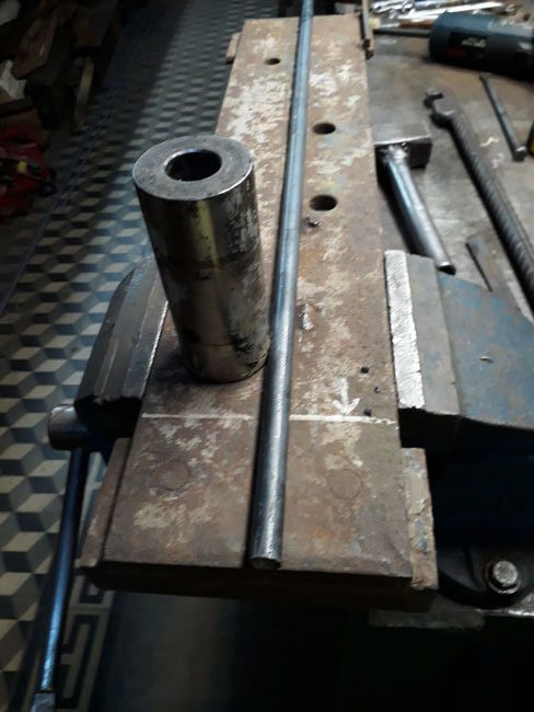
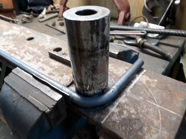
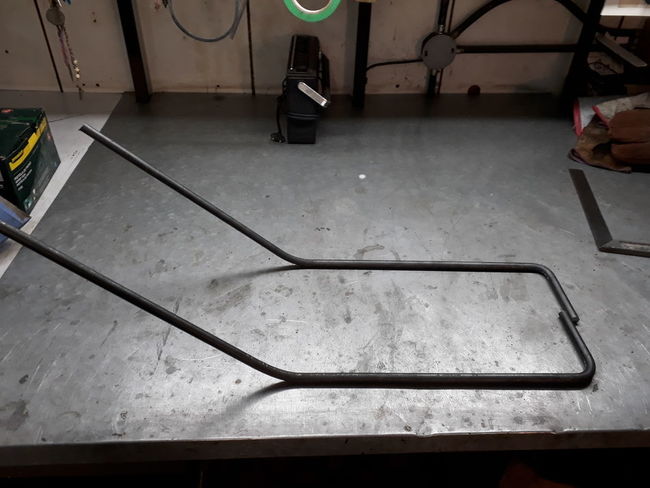
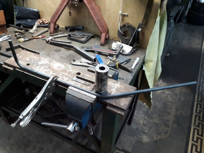
I'm still investigating how to move the steering column box to the right side.
I share a photo of a Minx LHD found here, and Minx RHD that belongs to a forum member.
Another question is the clutch bell housing and lever.
Some will have photos of the bellhousing
Thanks in advance!


-
Many thanks for yours replies!
I think the signals you say are one this?
Painted Bomb Disposal , I would like very much.


-
-
Hi Boys,I need your help .
Always in mind with having a British car from the Second World War.My favorite is Tilly, but here in my country there never was.
If post-war cars like the Hillman Minx arrived.
I want to know what differences there are between this car that I found here in Argentina and those manufactured during WW2. Were there many changes?
Can the steering column be moved from the right side? Is it easy or does it require many modifications?
Thanks in advance!


-
 1
1
-
-
Awesome Restoration! Beautiful! Thanks for sharing!
-
Good Job! Also my Ariel WNG need paint.
Regards
-
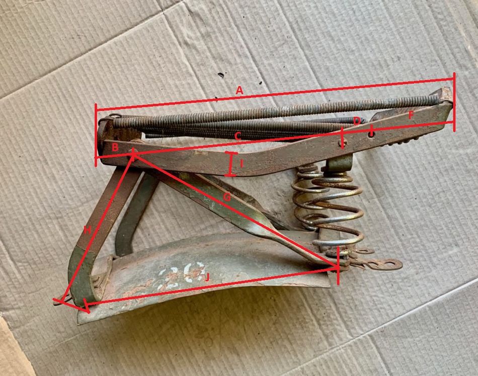
On 8/28/2019 at 3:59 PM, rewdco said:I have also found several examples of a slightly different version of this long ACUMEN pillion seat. There were always two holes for the spring brackets in the top frame. The "normal" version (as described above) uses the rear holes, whereas this slightly different version uses the front holes. The two rectangular cut-outs in the mudguard section are also 3/4" deeper, and the two reinforcing struts are a bit shorter. All these modifications make that the springs are mounted 3/4" further forward.
After some research I have discovered that this alternative version of the long Acumen pillion seat was only used by Ariel. Apparently in order to move the pillion seat enough backwards to avoid contact with the tail bone, the springs came in contact with the Ariel carrier. Solution: put the springs a bit further forward...
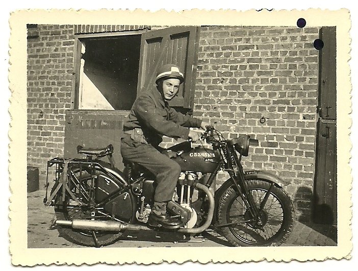

Hi Boys
Thank you very much for share this great information about WD Pillon Seats.
My 1944 Ariel WNG Registration Number C 5363724 is close to the bike can see in picture above.
I need reproduce the pillion seat , and need some measurements . Can help me?
Look the letters in the pics below
-
A friend need one of this, Price?
-
Ron Alex, thank you for your comments!
I always had the doubt if the originals were rod or tube ...
So should it be done with tubes? The ends with holes seem made by forging......My WNG should carry more weight and I should drink less beer
-
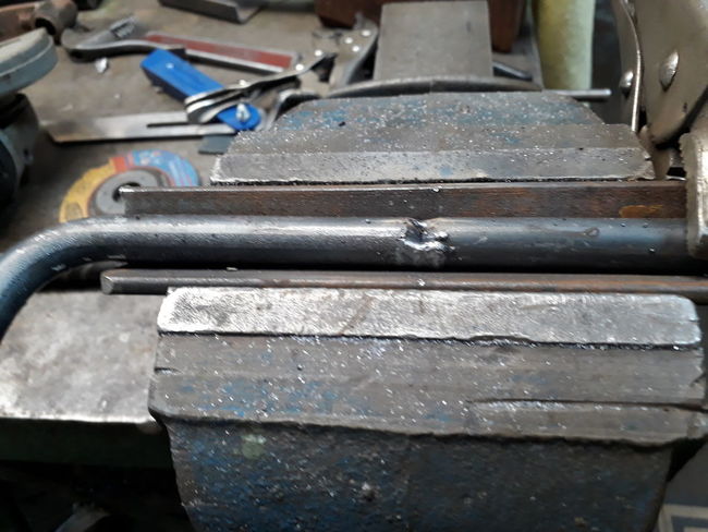
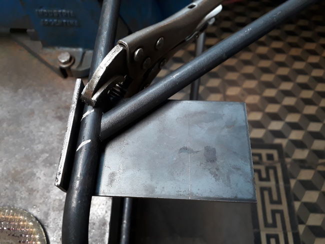
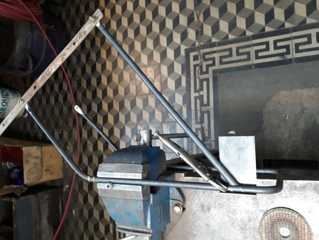
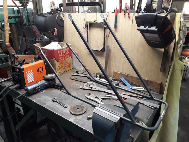
It still remains to finish the two short rods, but I will finish it once the rear mudguard is correctly installed
Regards
-
1
-
-
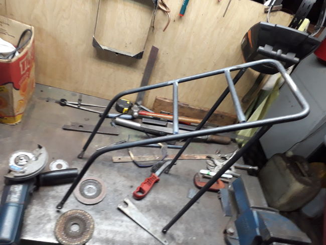
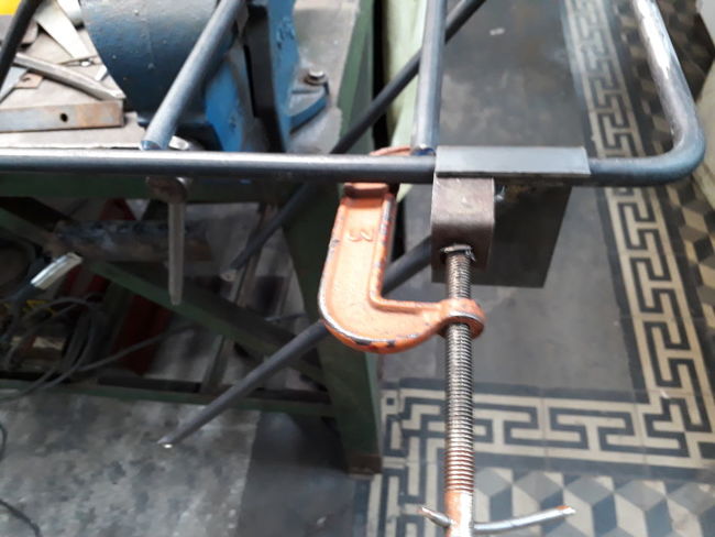
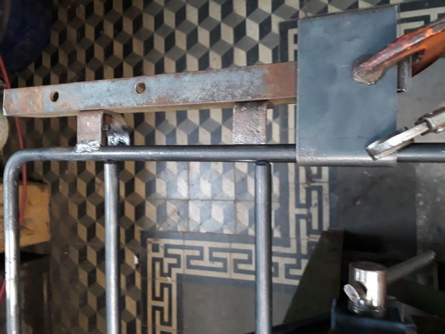
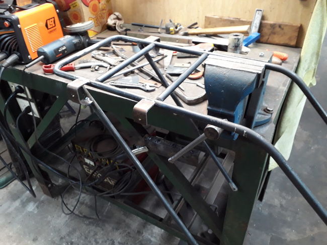
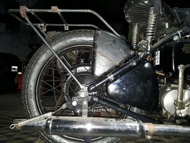
Hi Boys! Thanks to the measures shared here in the forum, I started building the rear carrier. My rear fender has missing parts, such as the hinge, which I will have to rebuild. I'm newby to iron folding and welding, so I have mistakes to correct even ...
-
1
-
-
Thank you very much for yours reply!
I found a bicycle with the same Mark V size , but maker unknow. Only serial number. I want upgrade with Mark V colour and accesories.
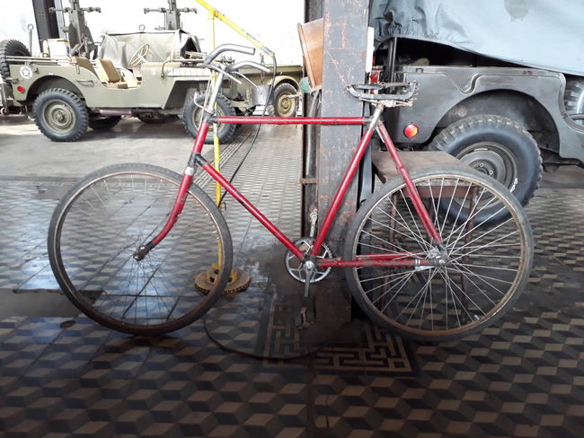


The bike seems to be this https://bsamuseum.wordpress.com/1934-bsa-gents-24-light-roadster/
What do you mean??
Regards!
-
Hi boys!
I hope you have started well this year!!
What color have this beautyful bicycle?
Thanks in advance!
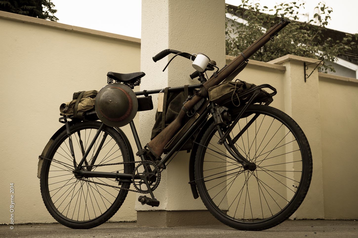 1939 Irish Army BSA military roadster by John O'Byrne, en Flickr
-
wdbikemad
Thanks for your reply.
The shipping to Argentina are very expensive, that's why it is difficult to buy large parts in your country.
Sometimes I take the trip of a friend to the USA, who travels frequently, and I make purchases with shipment to Miami.
Best regards
-
Hi Geoff! How are you?
Thanks for your reply and help!
weeks ago at Ariel Forum share the mesurements i need!
http://forum.arielownersmcc.co.uk/viewtopic.php?f=49&t=7909
About panniers rack , if you can make a drawing,It will be a great help!
Thanks in advance!
Regards
-
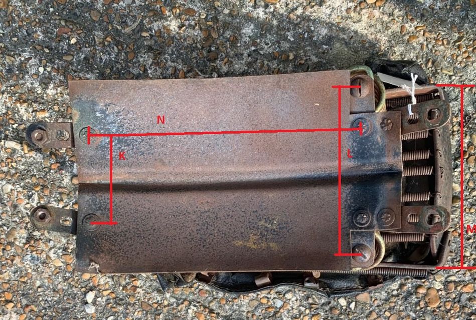
Hi fellows
I have a 1944 Ariel WNG contract number 294/23 /S.5514
Can anyone tell me the measurements you can see with letters in this drawing?
Thanks in advance

-
AWM Collection

KILIGIA, NEW GUINEA, 1944-03-12. NX4174 SIGNALMAN J. WALKER (1) AT HEADQUARTERS 5TH DIVISION SIGNALS, USING A 12 VOLT 300 WATT "JOHNSON CHORE HORSE", TO CHARGE BATTERIES IN THE FIELD.
KILIGIA, NEW GUINEA, 1944-03-12. NX4174 SIGNALMAN J. WALKER (1); Q128304 SIGNALMAN J.P. BELL (2) AND QX52479 SIGNALMAN T.J. CROWLEY (3), MEMBERS OF HEADQUARTERS 5TH DIVISION SIGNALS, PICTURED CARRYING "JOHNSON CHORE HORSE" 12 VOLT 300 WATT CHARGING SETS, FOR USE BY THE WIRELESS DETACHMENT.
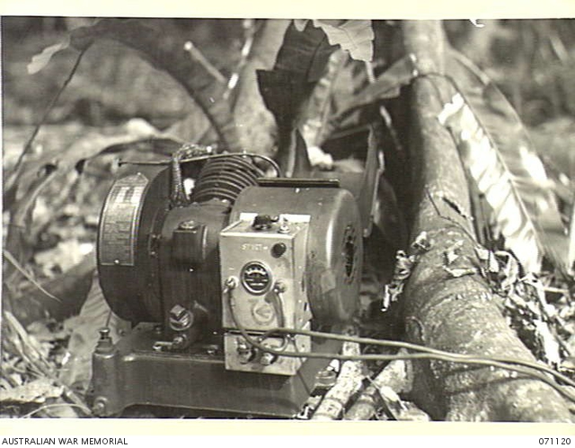
KILIGIA, NEW GUINEA, 1944-03-12. THE "JOHNSON CHORE HORSE" 12 VOLT 300 WATT BATTERY CHARGING SET, VIEWED FROM A CLOSE DISTANCE.
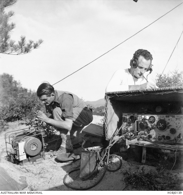
Two unidentified signalmen operate a field wireless set during tactical training of the 3rd Battalion, Royal Australian Regiment (3RAR). They were taking part in amphibious training on uninhabited islands in the Inland Sea. 3919 Corporal (Cpl) J Gerrans is sending and receiving messages on a wireless transmitter and the man on the left is cleaning the sparkplug of a portable petrol generator. Note the rechargeable Exide battery attached to the transmitter (centre) and the antenna erected above their position.
Regards


Help with Minx
in British Vehicles
Posted
Hi Kevin, your Minx have Master Cylinder Brakes?
I waiting the pics..
Thanks in advance!