


flandersflyer
-
Posts
264 -
Joined
-
Last visited
-
Days Won
1
Content Type
Profiles
Forums
Gallery
Blogs
Events
Articles
Store
Downloads
Posts posted by flandersflyer
-
-
Pretty cool stuff. Always had a "thing" for WWI/WWII submarines. Another WWI U-boat was found on the floor of the Baltic recently. It's in very good condition with the outer hull pretty much intact (due in part to the cold temps & low sodium content of that sea). She was lost with all hands so is considered a war grave.
Matt
its the SM U26
-
Not a tank but...
SM U21
This Uboat was deliberately sunk by its crew to prevent its surrender after Nov 11 1918
There was a recent documentary where a Uboat was located in the north sea after fishermen trawling the area were reporting snagging nets on something extremely hard where there shouldn`t have been anything
upon sending a dive team down ..there it was....
a completely intact Uboat from WW1 in excellent general condition
now..if it is the SM U21...then it isn`t a war grave
so...hmm...:cool2:
the salvage of the century...i would say....
-
Looks like an Ex-playground Valentine ,typically gutted. Anything to do with you Mr Rowe ?
Rob..................rnixartillery.
I remember back in the 80s there was a bren gun carrier & M10 tank destroyer at Thorp Arch...near Wetherby...amongst other bits n bobs
they`d both been turned into playground stuff for kids....
wonder if they`r still there?
-
One of the arms for the transmission brake mechanism was quite twisted.
[ATTACH=CONFIG]107610[/ATTACH]
I warmed it up until it was glowing with an oxy-acetylene flame and used a 1" bar through the eye to twist it back to as close to the original alignment as I could check by eye.
[ATTACH=CONFIG]107611[/ATTACH]
The rest of the week was taken up by a trip collecting more junk, Beaulieu autojumble and yet more painting.
is that a forged item?
If so then have you altered the grain structure by heating?
did you allow it to cool slowly?
-
To answer a question not asked... I have one of these and it is rather useful for this sort of thing. I used it to make the silencer and fuel tank for my Ner-a-Car.
http://www.axminster.co.uk/750mm-sheet-metal-worker
The bending and rolling capacity is rather more than the cutting capacity. And I think it was a fair bit cheaper when I bought mine. Curiously there are several on eBay at much higher prices than the Axminster one.
are these generally stable then when working on capacity?
do you get a true 90* all the way across when putting returns on sheet?
or do you find yourself going to 90* for the centre of any sheet being worked...then bringing back the ends to 90* with the tressle & copper hammer method?
mind you at the place i worked they had all stuff like guillotene`s, iron workers, rollers & brake presses...
-
It does OK in tension too, up to a point. You would imagine that an axle would be designed with the right amount of metal in the right places. BS 1452 described grades of cast iron by tensile (not compressive) strength, currently the grades are 220, 250 260 etc. 250 is 250N/mm2 tensile strength, or 17 tons/square inch. There are a lot of square inches in an axle casting.
It might be better. The Dennis axle appears to be a semi-steel. I re-bored the spring saddles once and it came off in curls rather than normal cast-iron swarf.
so...you think its a form of ductile iron then?
-
The major loads are contained inside the spring-pad and brake pivot casting. The static loads in the actual diff casting are fairly small. However I wouldn't care to guess the dynamic loads in the axle case when the wheels are busily bouncing about in shell craters.
The 1916 Dennis I play with has a rod in the place of the Thorny strap. It isn't especially tight, and I think that they are there as a safety restraint in the event that something unexpected happens to the diff (like landing hard on a rock)
it`l be to do with what Gordon says.
Cast has poor shear & tension strength....very good on compression.
lets not forget that the iron used in this diff will not be of the same grade as you can get now either....
-
On a Facebook site 'Vintage Trucks Australia' on 25th May, these two photos were posted.
What are they off? They seem quite wide so may be off a steam wagon.
Over to the experts.
Thanks Rick.
possibly a steam truck....such as the Garrett undertype...perhaps...
-
I struck lucky many years ago when a company decided to dispose of its optical pyrometers and I "inherited" one:)
A very useful non contact method of taking the guesswork out of red heat temperature checking.
If you have never come across one it is basically a light bulb filament in a low power telescope and a variable resistor with a temperature scale around the knob.
Look down the tube and turn up the power to the filament until it disappears/is the same colour as the hot surface. You then just read off the temperature on the scale.
This is still one of my favorite threads, keep up the good work!
i like that....
-
Thanks for the suggestion and yes, I had considered this. However the oxy-acetylene I have access to is around a 15 minute drive from my press, but which time the rivet may have cooled down!
But being serious when I looked into it the suggested load for hot heading a 5/8 rivet was 19 tons (44 to do it cold) and a little more than my press can manage.
Certainly happy so give smaller rivets a go.
we dont do `em cold.....rivets work on contraction see....
and i dont know where 19 tons has come from for hot setting......
you needs to get it white....it`l set lovely then ...without much force at all....
-
I have paid to have the front axle chilled iron blasted. I can blast the small components myself with alumina grit but the size and getting the rust off from the gap between the two channels would have made it very difficult for me. 20 pounds well spent in my opinion.
[ATTACH=CONFIG]103337[/ATTACH]
Then I gave it a coat of paint. Hopefully I can arrange a convenient time for Severn Valley Railway to replace the missing rivet for me.
[ATTACH=CONFIG]103338[/ATTACH]
Many of the smaller components had a top coat of paint this week.
[ATTACH=CONFIG]103339[/ATTACH]
make up another rivet out of some bar end.
get it white with the bottles and use the press to set it in....
-
no..it isn`t.Mammoth suggested getting a MIG welder, however the true answer is buy a TIG set. TIG is just so incredibly flexible being able to produce superb welds in steel, aluminium and even metals such as copper. Although relatively expensive and with the need for argon at all times having used one once you would never go back to anything else.Barry.
you need really clean metal for argon....
MIG will burn through most of the kind of surface contamination he can expect with what he`s working on.
An argon set would be good for the tinwork....as its a very localised heat which wont distort sheet materials when doing long runs....either that or stitch it with the MIG plant...
-
I would disagree with you,if you were wrong :-)
I suspect that you are watching the slag and not the weld pool underneath, but I am not a trained welder either.
I wonder if it is worth looking for a night-school course or similar?
Perhaps it is worth doing some experiments with scrap to get a feel for what each process variable does. I think that your welds above are what you get when you have the arc-gap too big and move the rod too fast. But as I say, I am not that much better than you.
He might be as well using iron powder rods for some of the heavier stuff.
and you dont need a heated quiver with em either....you can just set the plant up on low amps...then stab the rod onto some scrap...that`l warm it up...
we used to get some portugese powder rods that struck lovely...and lay`d in a lovely fillet.... ESAB powder rods tend to conk out half way down if they`r not pre-heated....
-
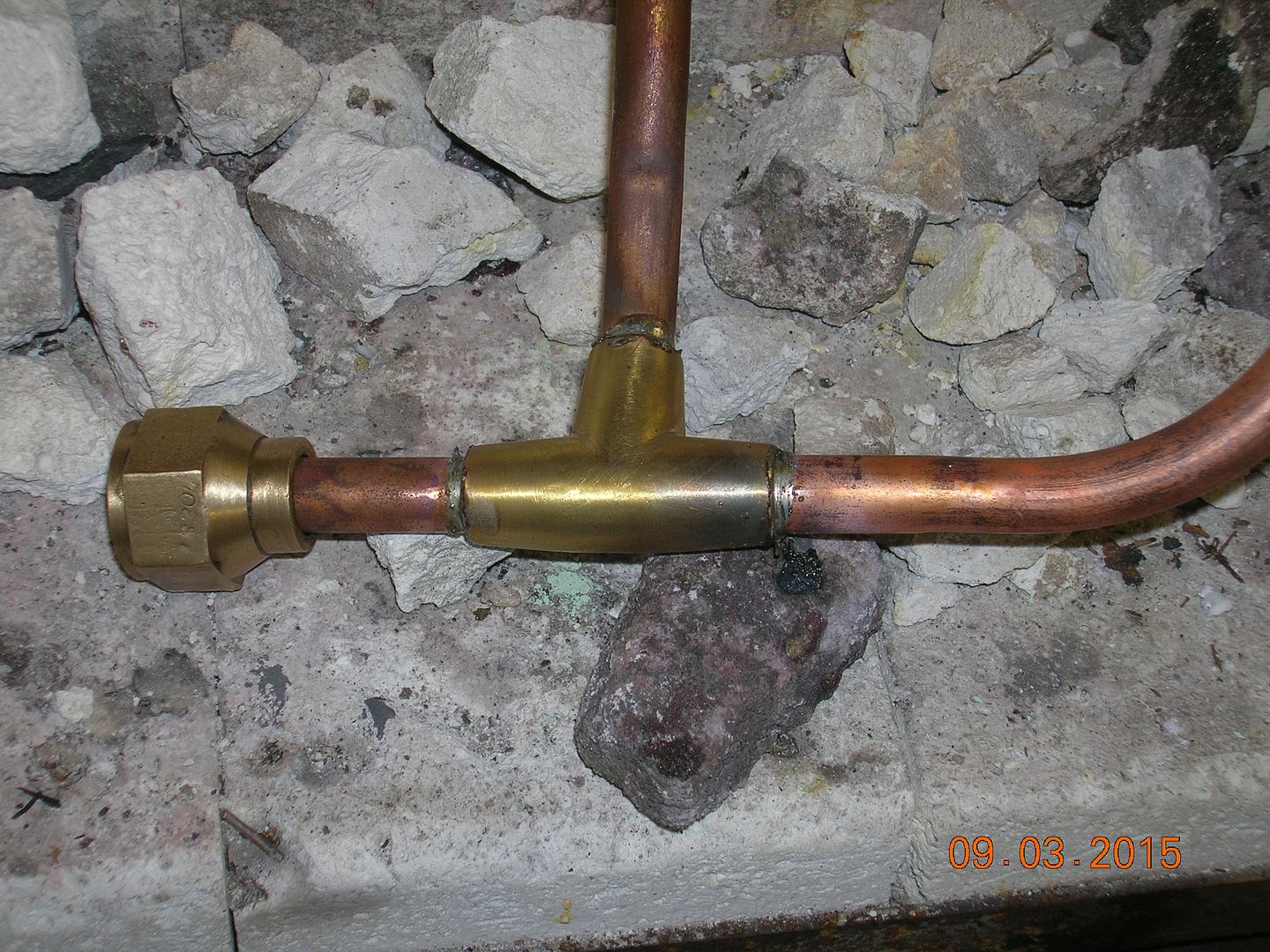
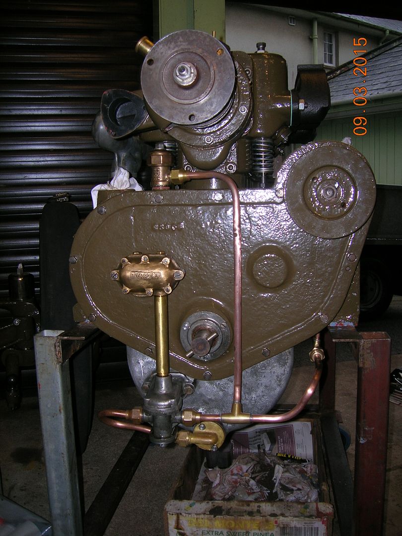
Progress seems to have slowed a bit recently as I have had to get a boiler test for my engine and sort out a deranged gearbox in the car. In between times, I have been earning a living. There is always something needs doing! Anyway, a few more bits to look at.
Firstly, the wheel bearings are lubricated with grease using Stauffers mounted on extensions screwed into the wheel hubs. We have six fronts and one rear of course! I have, therefore, turned up a second extension piece for a rear hub.
[ATTACH=CONFIG]103815[/ATTACH]
The next item we have spoken about is the track rod end and how it tightens on the ball joint when fully screwed down. I had planned to lap a couple of thou out of the cover to give clearance but in the end, cut a shim from a piece of 0.003" steel which I happened to find in a drawer. We will try that and see how it goes. I am sure that 0.003" clearance will not be noticeable.
[ATTACH=CONFIG]103817[/ATTACH]
Whilst rummaging in the back of the garage, we turned up a radiator mount and the beginnings of a second which had been started and then given to us by the chap who did the Hampshire Museum's military J originally. He turned up a better pair so these became surplus. The casting is tired but usable. The steel parts were intended to form a fabricated version for the other side so that one just needed finishing off.
[ATTACH=CONFIG]103816[/ATTACH]
I started by setting up a fly-cutter to the correct radius and then used it to bore the curve in a piece of angle.
[ATTACH=CONFIG]103818[/ATTACH]
Then it was square the ends up with a mill.
[ATTACH=CONFIG]103819[/ATTACH]
and file up the profile.
[ATTACH=CONFIG]103820[/ATTACH]
[ATTACH=CONFIG]103821[/ATTACH]
I put the tube in the lathe to barrel it slightly to more closely mimic the original casting.
[ATTACH=CONFIG]103822[/ATTACH]
[ATTACH=CONFIG]103823[/ATTACH]
I cut a wedge to go underneath the tube and drilled and tapped a hole for a bolt to hold the job together whilst welding.
[ATTACH=CONFIG]103824[/ATTACH]
As you know, welding is not my greatest skill but this lot would embarrass a pigeon! I should have asked a friend to do it but it really annoys me that I can't seem to get the hang of it!
[ATTACH=CONFIG]103825[/ATTACH]
[ATTACH=CONFIG]103826[/ATTACH]
Fortunately, a good file and some filler hides a multitude of sins!
[ATTACH=CONFIG]103827[/ATTACH]
All ready for a topcoat and fitting.
[ATTACH=CONFIG]103828[/ATTACH]
We won't need them for quite a while but I just felt like doing them!
Steve :-)
I`ll tell you what Steve..
your doing really will to get any kind of dimensions of what you`v had in regards to original parts (or whats left of em)...
i can imagine it being a real pain taking a measurement...then getting things `size` sometimes here...
and its coming along well by the way....
-
Here is a link to a site that is mainly about stationary engines and tractors, but they posted a couple nice series of pictures about the production of war equipment during WW1.
http://mototracteurs.forumactif.com/t18520p60-les-usines
Marcel
no guards or interlocks on any of them presstools...
you`d get lynched for running a shop like that now....
i wonder if they had a press register back in them days?
-
Steve, the brake rings look great.
The old lathe is interesting, no tailstock and the toolpost looks as though it belongs on a capstan lathe; presumably it was intended to do a simular job as you have done on the brake rings with repeatable accuracy on large batch machining.
John
caus its a facing & boring lathe...for swinging large billets...
-
would the fronts have been faced off originally?Our current efforts are directed towards getting the back axe and wheels fitted to give ourselves a rolling chassis. To that end I have been working on the brake drums. Readers may remember that we managed to break one whilst trying to take the back axle apart and that the remainder were in very poor condition. Our joiner friend, Mark, did the donkey work for a pattern which I finished off and Father took to the foundry. Well, the castings have been in my living room for a year, leaning against the book case waiting for the day when they would be machined. Well, that day has come! Thanks to our good friend Adrian who once again very kindly made his huge Oldfield and Schofield lathe available, the job is done.Set up in the jaws on the face plate, I started by boring the first one through.
[ATTACH=CONFIG]103440[/ATTACH]
The odd toolpost arrangement forced me to mount the tool inverted and cut on the far side. This was not as stiff as I had hoped but I managed to keep the chatter to a minimum by taking only modest cuts
[ATTACH=CONFIG]103441[/ATTACH]
[ATTACH=CONFIG]103442[/ATTACH]
Then a knife tool in a conventional position to face the front and finish the diameter.
[ATTACH=CONFIG]103443[/ATTACH]
[ATTACH=CONFIG]103444[/ATTACH]
[ATTACH=CONFIG]103445[/ATTACH]
The bore and rear faces completed I reversed the chuck jaws and faced the fronts.
[ATTACH=CONFIG]103446[/ATTACH]
[ATTACH=CONFIG]103447[/ATTACH]
[ATTACH=CONFIG]103448[/ATTACH]
[ATTACH=CONFIG]103449[/ATTACH]
[ATTACH=CONFIG]103450[/ATTACH]
Job done and it only remains to drill, spot face and fit them to the wheels.
Thank you Adrian! We couldn't do this without our friends!
Steve :thumbsup:
-
Yes, we could shim it and that was my first thought. However, none of the joints we have dismantled have had any shims at all and it is so nearly there that it only wants a couple of thou to get it right. We will have to see how my patience lasts whilst lapping it out!
Cheers!
Steve
they may have done when new.....but as wear took its toll the shims were removed to take up any slap...
it would seem prefectly sensible to have used shims.....let us not forget that it was the fitter that made it all work smoothly back in them days...
-
I made a very simple puller for the tappets from some scrap I found under the bench.
[ATTACH=CONFIG]101460[/ATTACH]
Then used it to extract the tappets from the crankcase.
[ATTACH=CONFIG]101461[/ATTACH]
A roller runs in the slot, but in most cases they are broken off above the slot.
[ATTACH=CONFIG]101462[/ATTACH]
One had been replaced with a bronze one but most are cast iron. I stuck some bits of MDF together and turned them in the lathe to make a pattern.
[ATTACH=CONFIG]101463[/ATTACH]
Then painted it up. I decided it would be easier to machine them with the hole filled in so have not made a core box. It is only a 20mm bore so there will not be much wastage and they would probably cost more with the hole in. I will machine some of the flange away to make them into the left or right hand version.
[ATTACH=CONFIG]101464[/ATTACH]
i`m not being funny or owt....but have you not considered machining these cam followers from billets....rather than going for cast...
its just that you may get problems again in the future....
-
The last part of the job was to solder it up, using solder paint and then a quick clean before fitting it and heading back to Leicester
so...shouldn`t be long then til you can bang some juice in it.....a video of a bench run would be nice...:cool2:
-
Be almost a shame to put a body on it.
As for the hot oil trick, ehemm it's been mentioned several times on this forum. A better mixture is old gear oil heated with disiel, stinks but moves almost anything.
I`v heard Coca Cola does it as well.....
-
they do copper cylinder tops n bottoms as well like this.....for your hot water cylinders you have at home.....They make gas cylinders that way. But I can see it being tricky to do it as a spinning operation as you are trying to compress the metal into a smaller volume. -
I guess it keeps the edge more homogenous, and so cracks and wrinkles are less sure where to start.
The spinning videos all seem to do a lot of edge trimming with a tool for the job, so it shouldn't be too hard to trim to perfect circles when mounted and "set on" the former.
my hands are doing OK thank you very much....
got some of that O`keefes stuff....seems to be helping...
-
was working once at this place.....all it were was O/D`ing and facing off some stainless blanks....Thanks Steve. It sounds like I should be making a metal chuck/mandrel so that it doesn't get a grip. I hadn't thought of drilling the middle though. I will put a hole in the centre of my blank so that I can have a locating peg to prevent the unformed disc from flying out at speed. That might prove more excitement than I want!Steve
they`d come in straight off being parted off on a big oil country stanley...
then we`d swing em in a ward 7...
the razor sharp edges like sawblades at 1500 or so RPM...
they cut yer gloves to ribbons just mountin em.....lol...


buried and abandoned tanks
in Tracked vehicles
Posted
U21 is in generally very good condition (apart from some frontal damage when she hit the seabed nose first)..but from what i could make out watching the doc...the pressure hull looked to be OK...
it could be raised
anyway...back to tanks...