


flandersflyer
-
Posts
264 -
Joined
-
Last visited
-
Days Won
1
Content Type
Profiles
Forums
Gallery
Blogs
Events
Articles
Store
Downloads
Posts posted by flandersflyer
-
-
You've still got three points of location on that pump so if it were me I'd just ride it rather than attempting to weld or braze a bit on that foot....its age related and honest John...
One of my old radial drills (the big Asquith one) has a cracked mount on the forward/reverse transfer box...
It's clearly been like that for years...and I've no intention of introducing unnecessary stresses into it by attempting to close it up...its happy & settled as it is...
-
22 hours ago, Minesweeper said:
And mine for me, too! We each had them for Model Engineering work but have stretched their capabilities to the ultimate over the lorries.
I've a load of old machine tools in storage...
They're all older flat belt driven types...designed to run off steam via overhead lineshafts...
-
 1
1
-
-
That Myford lathe's done some graft for you Steve...
-
Nearside chassis cracking is probably due to the bad edges of roads at that time....
The sides of roads being potholed & rough...
(a bit like nowadays actually)
-
And here's a bit on coopering as well:
-
There's another one here:
-
1
-
-
Lathe & drill running off a lineshaft...
Grinder on electricity...
DC I would assume...
-
In regards to the electrolysis bath mentioned above...
Use this process in a well ventilated area...as it gives off hydrogen gas whilst in use...
-
Put some STAG jointing compound in it...
-
-
Outstanding
-
2 hours ago, Old Bill said:
We have had a nice day again and have fitted all of the rope hooks. Definitely a two-man job to avoid climbing in and out of the back all the time.

Another job ticked off! I also took the opportunity to crawl underneath and have a look at the sump.

Once I had wiped the oil away, it became obvious that some sort of filler had been used to fill some porosity in the casting. It looks like soft solder.

The oil is leaking and steadily dripping from the joint line between the two metals. The question now is what to do about it.

I am wondering if I could cut some of it out with the Dremel and fill the resulting groove with Plastic Padding or even a silicone gasket material. Any suggestions please chaps?
Steve
")
Drill it out and have someone with an argon set come round and run a fillet of weld in there...
-
15 hours ago, Old Bill said:
We had a nice day out yesterday at the Bovington Amiens Commemoration Day with all the lorries you can see above and some more. No doubt Tim will post a report shortly.
In the meantime, we now have a horn! Thanks to Barry's photos above, I have made up some representative bits.


These were done in Leicester and I have since cleaned them up with a file and broken all of the corners. Then it was on to the base which is bolted to the curved top edge of the dash plate.
My usual favourite, silver-solder!

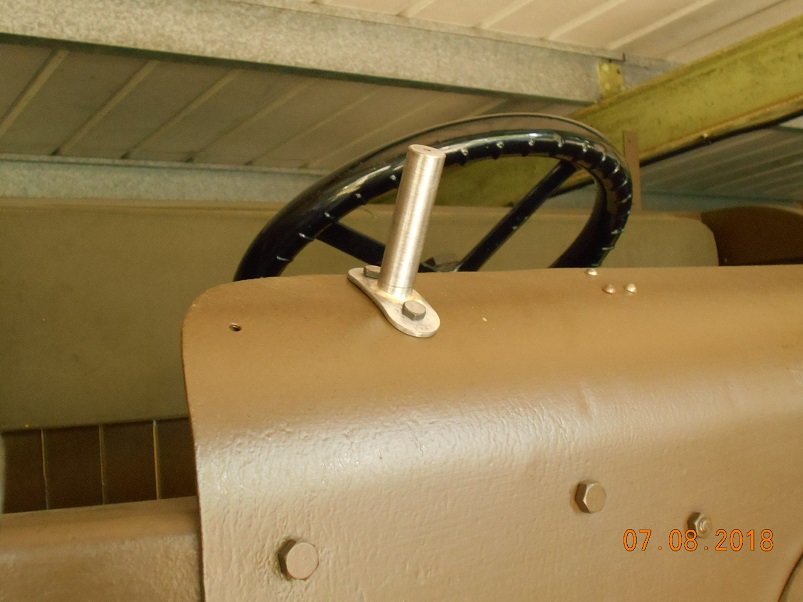

Getting closer to being legal. We only need a rear lamp bracket to complete the requirements. Hood frames are in the plan for today.
Steve
I'd weld that bracket Steve as if it drops off that vintage horn will be under the wheels...
-
On 7/29/2018 at 3:51 PM, DAN THE STEAM said:
Success, we have just towed the Halley about four miles about the place trying different road conditions, curves speed ect.
The steering is perfect, everything works first class, had the Halley up to 26mph and felt very stable and could be steered with one hand easily, even done some full lock manovers with no dragging of outside wheel.
This is a large step in this truck as it proves all my hard work so far and sets the foundation firm for building the rest on, maybe Brexit should take some notes from WW1 truck builders!
Next job is to finish working out and machine adaptors for the gearbox to pair to the chassis, then try and sort out the cab and finish rear body including hoopsticks.

Brexit would be fine.....if Bunches of remoaning traitors to this country didn't constantly...just continuously attempt to interfere with it...
Oh...
And nice to see the Halley is progressing...
P. S. I've just acquired an early turret lathe by Alfred Herbert....WW1 era....or just after...
For flat belt running from a lineshaft...
-
On 7/14/2018 at 9:40 AM, David Herbert said:
I have a DIY grade Bosch POF500A router that I use as a die grinder (have a look on Ebay). I have both 1/4" and 6mm collets for it so can hold both router bits and grinding stones in it. There is a parallel section where it clamps into the router frame that is just right for clamping it to a lathe and the bearings are fine for light grinding.
If anyone is thinking of using any kind of toolpost grinder on a lathe, do go to some lengths to stop the grinding dust getting on the bed in particular but also anywhere there are parts moving against each other - which on a lathe is pretty well everywhere ! Even the chuck will not be improved by a sprinkling of carburundum grit.
David
Also to note is the siteing of surface Grinders in proximity to lathes, milling machines etc...
-
1
-
-
Just now, andypugh said:
I think they called it "seasoning".
Googling for "seasoned castings" found this: https://www.jalopyjournal.com/forum/threads/factory-storing-castings-outside-to-age.1015700/
Weathering Mr Pugh... ☺️
Left outside to "weather"...
Basically to settle down and normalize over a period of time...before jigging up on a lathe/miller/borer for 1st & 2nd op machining process....
-
39 minutes ago, Old Bill said:
That is one beautiful car, Ed. 'Shiny' and 'refined' are not what we usually see on this forum as 'functional' and 'matt olive drab' are more the norm! However did you find us?
Many thanks for your thoughts. From my measurement of the original piston I think that Thornycrofts probably went for a clearance above the top ring of 0.017", between the rings, 0.012" and for the remainder of the piston, 0.005". If I hone the bores another 2 -3 thou then that would give me a general clearance of 0.008". If I take another 9 thou from the top land and 4 thou between the rings then that would give me something comparable with 'new'. I will take a good look at the rings and replace any that are obviously damaged. I am curious as to why they should have stuck in the bottom of their grooves on 2 and 3 pistons as all were quite free when I put them in. I will have to ease the grooves as well.
In the mean time, I have been pushing on with the wing brackets. They are a horrible job and no fun at all. This is not helped by my welding incompetence so there has been no satisfaction in them being nice. Oh well. They are tacked up now and ready for a proper welder to put them together for me. He is probably reading this and going 'Oh no, not again'!


Steve
2 & 3 pots being amidships on the engine so maybe run slightly hotter...?
-
Ben...
Once it's been out and verified as running OK you may want to pass on several info about ring gaps & piston clearances on this to the Goslings...if they haven't resolved the issues their having with the Thornycroft power unit...
(I'm assuming you documented such data...?)
-
Make up 1 copy of the pistons being used in the thornycroft...
Get a temperature on the engine of when it locks up...
Mic the copy cold...then heat it up in an oven to same temperature...mic it again and compare it to the bore...
-
I think you'll make it...just...
-
14 hours ago, Old Bill said:
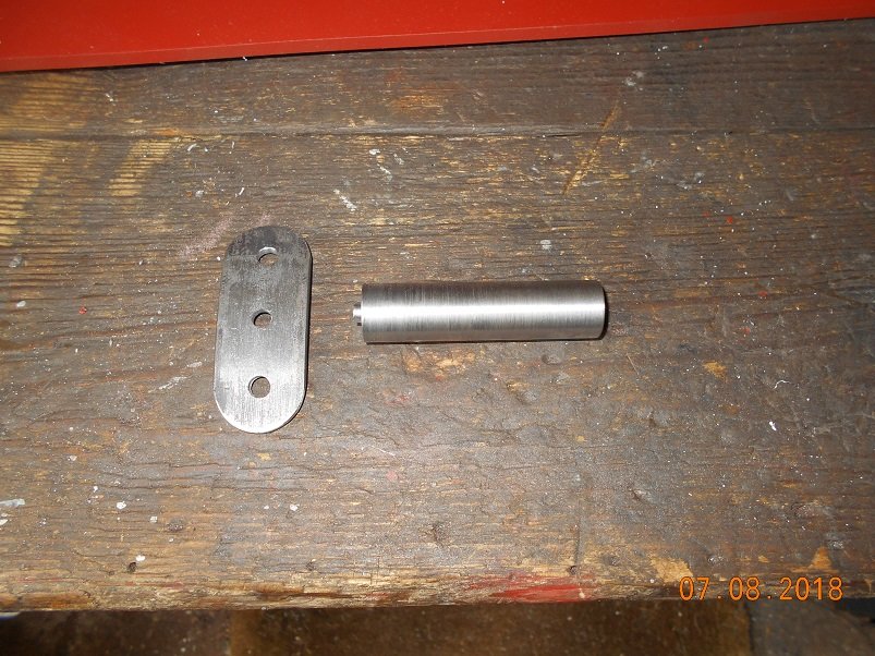
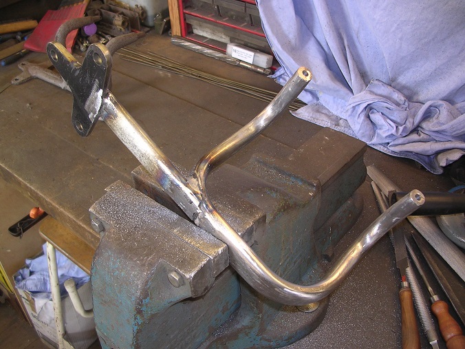
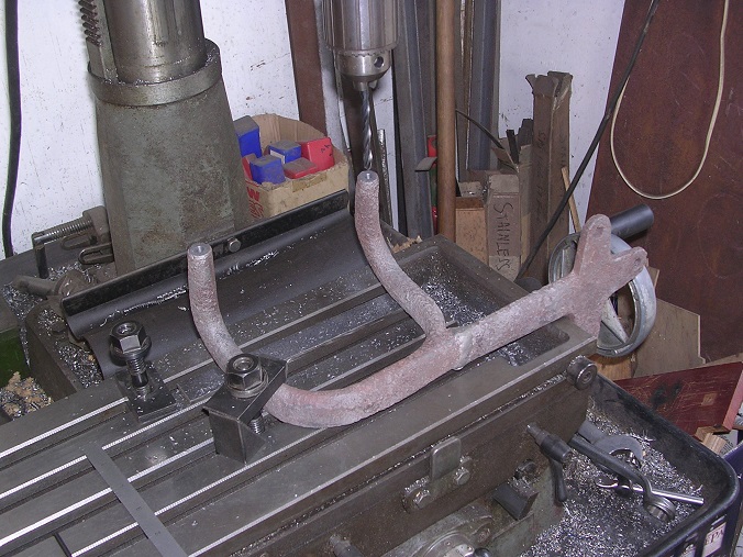
Something else we could manage without are the sidelamp brackets. However, they are very much part of the appearance of the lorry so I have been pushing on wiuth them. We are fortunate to have one original bracket. However, it had been squeezed up to carry an electric lamp and also snapped off and welded at some point.It looks very much like a casting to me although it could be a forging. It is quite sifficult to see how it was made. However, if a casting, I felt that my chances of bedning it back without snapping it were slim. However, I had to have a go.

I tried bending it red hot in the vice using an adjustable spammer for leverage. Amazingly, I got away with it.

And he second bend.

To flatted nt eshank, I put it in the press where I could control the force nicely.

Well, that was a bit of luck. I was expecting to ruin it but in the end, it came out OK and I only had to make one more. I had some pices laser cut or, I suspect, plasma cut as the main part is 15mm and quite tapered.
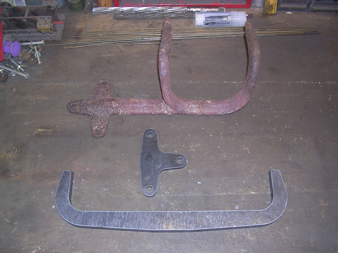
It is elliptical in section so a lot of angle grinding and filing later, we had this.


I also filed the edges of the back plate and cut the straight piece to go in between. This, I did by hand and then again, filed elliptical.


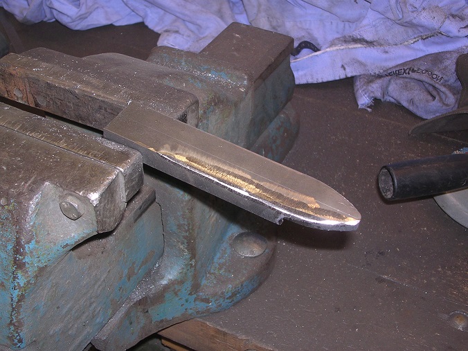
Next challenge was to work out how to bend it.

In the end, I put it in the press and bent it cold, a little bit at a time and by eye.


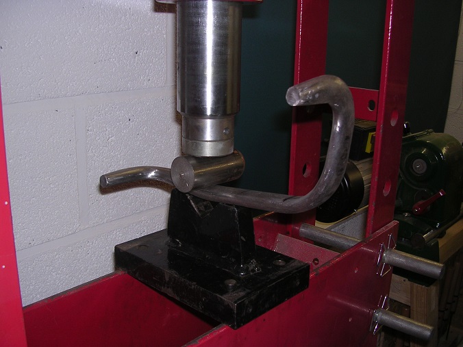
It came out OK but the surface suffered a lot of bruising which I had to file out afterwards.


The holes were drilled for pegs to be located in the top. The pegs were later silver soldered into position.

All set up for welding.

My welding is still abysmal!


Thank goodness for angle grinders and filler!

Whilst the filler was going off, I cut the damaged pegs from the original bracket and drilled for new ones. It drilled like cast iron and I am amazed that I managed to bend it without it snapping.

After dressing of the filler and another round of filing and polishing, we have a pair of brackets. Very fortunately, I welded the second to be a mirror image of the first, not a direct copy!


Even the pegs are the right distance apart.

Into the paint shop tomorrow.
Steve
What made you think it were cast Steve....?
As someone else has said it's likely wrought iron...
You can tell the difference by braying it with a hammer cold...iron splits into fibres...unlike steel...
They'll have had blacksmiths working at Thornycrofts....
-
I reckon it won't take too much now to get this started...
There should be bets on how many swings...
I'm going to say 7
-
8 hours ago, Old Bill said:
As Dad has mentioned, we are having a bit of a blitz this week with the first priority to get the engine running. First thing we have done is to evict the poor old Autocar from the shed and sheet it over in the drive to give Dad somewhere to work. There is only so much clambering over stuff one can do so we are trying to make it easier to meet the deadline.
Once the decks had been cleared, I fitted the oil filler, if only to get it safely out of the way.

Once in position, we had to try it out of course.

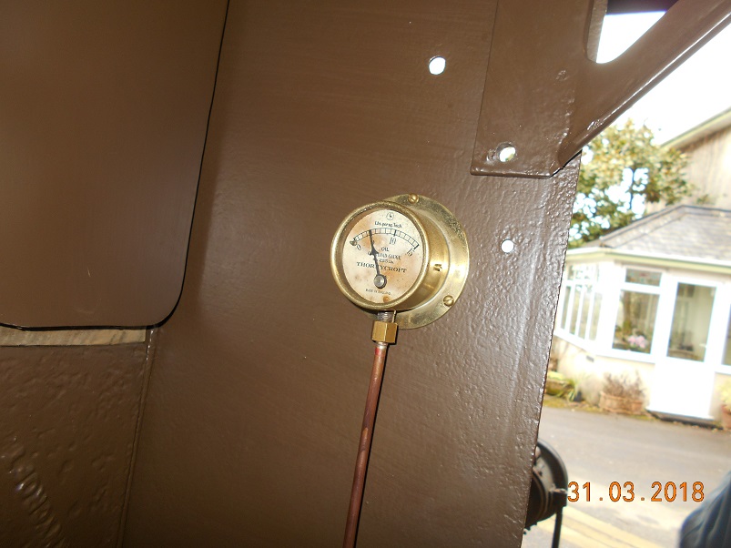
About a gallon and a half later and the float began to indicate, much to our surprise as we expected that it would need engine vibration to move it.

I wanted to prime the oil system before we run it so I took the plugs out, disconnected the oil pressure line and swung the handle until I ran out of breath. Well, it is six and a half litres even without the plugs! On the second go, we saw some oil come out of the pipe so I reconnected it. The next swing saw the gauge registering. It is coming to life at last!
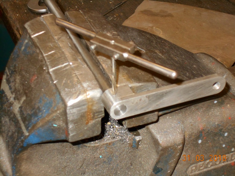
The next task was to mount the magneto. During my last week off, I made the magneto coupling so all that was needed was the flexi-disc. This is a piece of leather with four holes in it. Our museum friend, Mark who does our leatherwork, found a complete hide of pump leather in a skip some years ago. He rescued it but didn't know what to do with it. This was very fortuitous for us as most of it has found its way into our lorries! Mark used it to make the propshaft couplings and has also given me a piece for general use. As it is over 1/4" thick, it was ideal for the flexi disc. I marked it out with scriber and dividers and cut it with the Stanley knife.

The centre hole was taken out with a wad-punch but I don't have a 5/16" wad punch here and wondered what to do about the stud holes.

In the end, I used a wood bit run quite fast and that worked out OK>

The coupling was assembled and the magneto bolted up from underneath. All was well so I moved onto the advance levers.
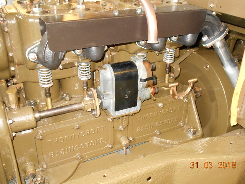
I had made the levers during my week off so I just needed to cut a shaft to length and pin them on. I have put taper pins through the shaft but looking at the pictures now, what I should have done is put a much larger pin through the block but offset to catch the shaft at the edge of the hole. Oh well. I expect that this will be OK and I shall know for next time.
The other end was pinned in the same way.

And then final assembly with the location tube pinned between the arms of the casting to stop it moving axially.

Throttle linkage and HT leads tomorrow!
Steve
Nearly there then Steve...
-
On 19/03/2018 at 9:05 PM, Old Bill said:
A week off work, Hurrah! I could get used to this. An opportunity to really get things done!
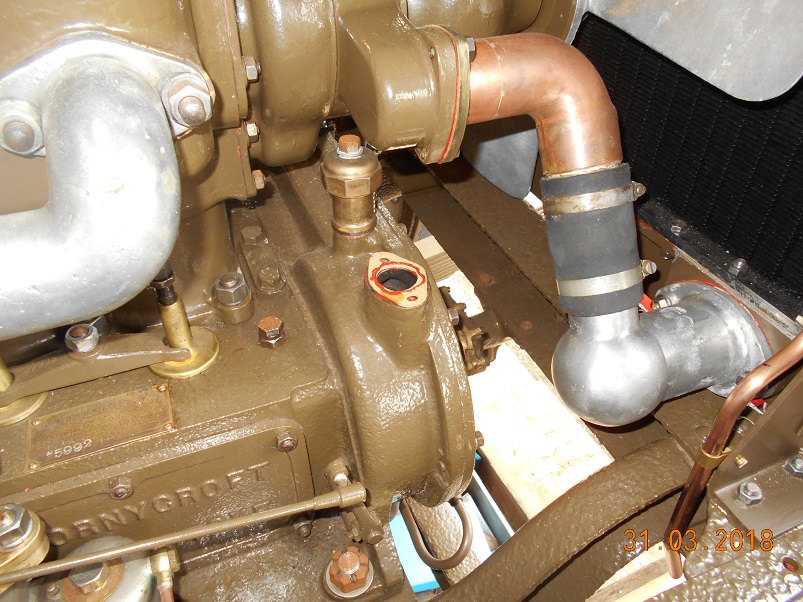
I think the reason they all lost the oil filler is that it is copper and brass. Should anyone need Thornycroft information to aid their rebuilds then we are always only too delighted to help. I don't have full engineering drawings of everything we have done but I have an enormous folder of notes an dimensions. That is what comes of nearly 30 years of collecting data!
Back to the oil filler. This is what it looks like.

As you know, I have been struggling to bend the tube so, for the sake of expediency, I have put together an assembly using commercial fittings. This will be replaced when I find time to make a special pipe bender and can do it properly with no time pressure.
I made the base flange a long time ago when I was getting bored with pattern making and desperately needed to cut some metal.
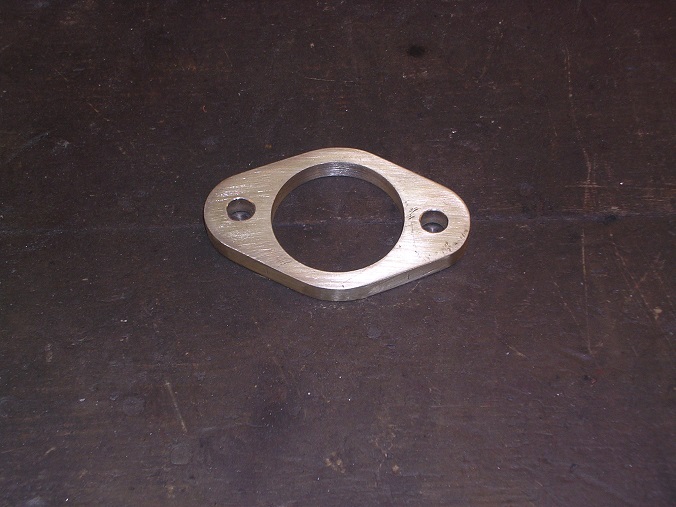
The fittings were a gift from a pal in Exeter.

Fluxed up for silver soldering.

A good clean and job done!

Then onto the cup. The only way I could think of producing it was by spinning from a sheet of brass. The first job, therefore, was to turn up a 'chuck'. I found some pieces of old school workbench which I laminated. These were beautiful pieces of beech.

Then off we go. A disc of 20swg brass annealed and then rubbed with soap as a lubricant.
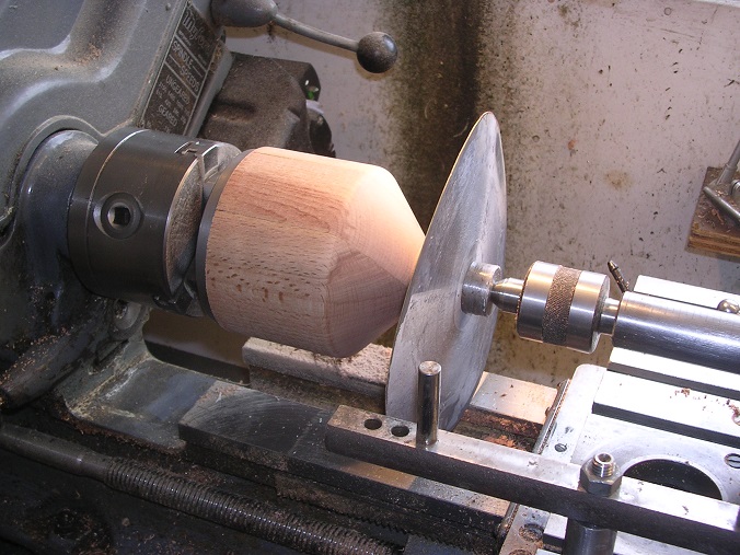
I am not yet skilled enough to do it without creating ripples or to spin the ripples out. My most successful solution to this problem has been to remove the job and beat the ripples out with a mallet on a piece of wood before having another go.

And again!

This cup has a beaded top edge which is something I have not done before. Unfortunately, I got a bit carried away and broke the top flange right off. There was just enough metal left to turn over but it is rough and cracked so I will make another when I get around to bending the pipe.

It will do.

Then spin the lid in the same manner. This time I managed to bead the edge without breaking anything.


The lid needed a knob which has a projection underneath to secure a spring. This was a nice turning job.


Then the moment of truth, solder the tube to the cup. This actually went surprisingly well but I did treat it with solder paint first, hence the runs which soon cleaned off.

The original has a gauze inside to prevent anything from entering the sump. Whilst poking around the workshop this afternoon, I found a shield from the back of an old fan oven, rescued for some reason. It was perfect!
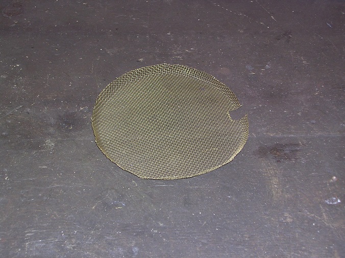
A rummage in the spring box found something suitable.

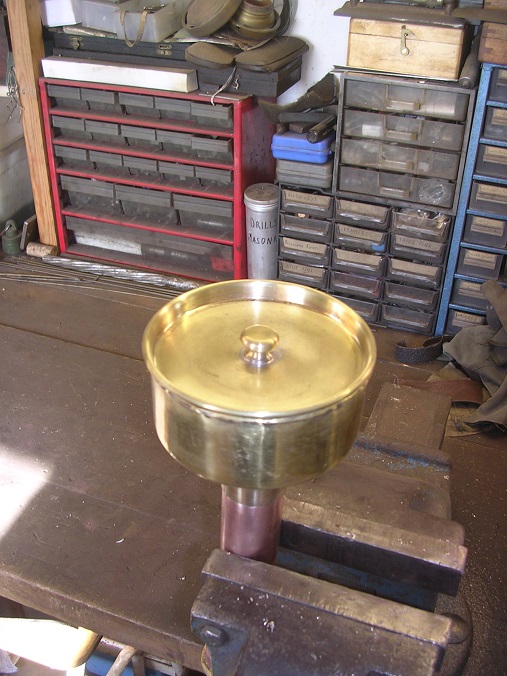
Job done!

This is only temporary until I can make a better one but it will allow us to run the engine. Start up is going to be the Easter weekend.
Back in the shed tomorrow. Foot brake bits next.
Steve
That's worked out OK Steve...
I've not done any metal spinning myself...but I've heard its an acquired skill...
From what I've seen of it being done is that you've got to steadily persuade it over the form...
I think a lot of metal spinners push it beyond the edge of the form...then part off to length...


")


WW1 Thornycroft restoration
in Pre WW2 vehicles
Posted
Check all terminations are tight including any switching within the mag...
Switching DC currents behave very differently to an AC waveform...