


Chris Suslowicz
-
Posts
501 -
Joined
-
Last visited
Content Type
Profiles
Forums
Gallery
Blogs
Events
Articles
Store
Downloads
Posts posted by Chris Suslowicz
-
-
I have two of these transformers in my pile of stuff. I cant remember where they come from or who I got them off. Are they of any interest to anybody?
Thanks
Tim
Yes, they're the later (tropicalised) version of the HT1 dynamotor for the British WS19 power unit.
Certainly of interest to me.:-D
Chris.
-
Hi,
I have Canadian 34' aerial with ground spike, guys, pegs and leather bag. When you say "British" did we have another version?
Some photos:
(That ground spike does not look original - more an example of the welder's art, the originals were cast/forged.)
The British mast was the "34-ft steel vertical aerial" and came in a big canvas bag with shoulder strap. It's made up of 3-ft Aerial Rods 'D', an adapter and some Aerial Rods 'F'. Somewhat flimsy and tricky to erect without bending/breaking the rods. Also (apparently) prone to falling down if any of the guy ropes got shot away. :-D
There's a 'kit layout' of that mast on Keith's WS22 page, here:
http://www.royalsignals.org.uk/photos/ws22/index.htm
It remained in service into the 'Larkspur' era before being replaced by the 27-ft telescopic mast (very obviously based on the Canadian 20-ft and 34-ft mast kit that you have part of).
The kit later became the 32-ft vertical aerial with the replacement of the 'F' rods by the 14-ft sectional whip aerial from the WS62 - this allowed everything to fit in the 'golf bag' carrier (Bags, Aerial Gear, No.2, Mk.II) instead of requiring an additional carrier tube for the 'F' rods that are too long to fit in the bag.
Parts of the kit remained in service for a very long time, the pins for the guy ropes are "Pegs, Aerial, 'A' from the early 1930s, the ground spike likewise, and those (excuse pun) soldiered on into the larkspur era, the pegs being used to anchor the flat mast baseplate on soft/sandy soil, and the spike as a mount for the C42 and C45 aerial tuning units when dismounted from the land rover wing as a remote aerial.
Parts of the kit turn up fairly regularly in the usual places, but finding a complete kit is almost impossible - the 8-oz ball-pein hammer is almost always missing! (Also missing are likely to be some of the 'D' rods due to breakages, and guy assemblies (due to rot).)
Chris.
-
Probably be seeing how 2x 24V 200ah (ie 8 12v 100ah batteries) does as the control system is parallel/series/series with weak field, so 48V max. This is half the original design but should suffice and give a reasonable run time. Controller is rated at 44 amps. Testing has so far involved 2 12v spare batteries which has proved promising. Luckily I have competent persons to oversee what I'm doing or thinking of doing!
I'm very appreciative of the help and guidance I've received on this forum.
Are you restoring a submarine?

Chris.
-
I just noticed the 'A.P.' part number. "Admiralty Pattern" so probably off something very substantial!
Also, 60 volts at 15mA is 0.9 Watts, so your series resistor will get quite warm and needs to be rated at 1 Watt or more.
Chris. (G8KGS)
-
Many thanks Iain. I had to use 2x 2k resistors in series as they are the nearest to hand, and although I realise there is a % error it's near enough. It works.
...it's not critical as it will be used to monitor voltage drop to prevent - hopefully - overdischarge of a 60V battery.
Er, how big is the battery, because 15mA is quite a considerable current drain for a meter, and you should be able to get something far more sensitive than that without too much difficulty. (500 microamps (0.5 mA) was common for panel meters during WW2, and modern test meters are usually a tenth of that.)
Chris (G8KGS)
-
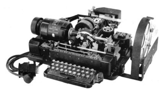
Having a sort out again.....Test Unit Radio Type FT1, NSN 6625-99-949-1358. Looks OK to me, has a test cert that expired in 1988 £50. Any use to the radio experts ?
Of limited (close to zero) use without the "Big Bag Of Connectors (and connecting cables)[TM]", unfortunately.
Chris.
-
I am doing a bit of research into what equipment was carried by mobile Special Liaison Units in '44/45. In particular, what radio aerial equipment. I have a description of what they used from a Dodge or Guy 15cwt as follows: "a bag with a sectional mast, aerial wire, guy ropes and mast base". But what exactly would that comprise, so I can try and find this equipment? Thanks!
Probably the general purpose "Aerial, Vertical, 34-ft, Steel" consisting of a canvas bag and a load of Aerial Rods 'D' plus ancillaries. (It could be used to make 2 x 12-ft masts if required, an 18-ft mast or a 34-ft vertical aerial.)
See Keith's WS22 page (towards the bottom): http://www.royalsignals.org.uk/photos/ws22/index.htm
The "aerial wire" could be any of the ready-made aerials, the 100-ft No.5 (with links to allow pre-set lengths), an 'all-wave' longwire, or packets of copper wire and loose insulators for making up your own aerial to suit requirements.
The SLU had specialist signallers so would not be reliant on the usually available wire aerials and could assemble something rather more efficient from available stores if required.
Chris.
-
I am looking for a Volt and Amp meter so that I can complete my restoration of a WW2 Norman 110v generator set.The ones currently in the unit are broken.
The dimensions of the meters are ;
diameter 2 1/8th"
length 1.5" ( not including the fixing bolts)
distance between fixing bolt centers 1"
Any help or advice would be much appreciated.Thank you.
All the best,
Kevin.
Those are standard meters for the period. The ammeter should be simple to find (I may have one in the bits box), but the voltmeter less easy - it may be necessary to transfer the scale plate to another meter.
Both meters are the 'moving coil' type, so are intended for DC. Is the generator off a searchlight or something like that? (Current is a bit low for a welding set.)
Regards,
Chris.
-
The complete station list for Bedford MWRs listed on WFTW Vol 2 (page WS19-38/39) suggests that MWRs used operationally by armoured formations were supplied with 2 or 4 170ah batteries rather than the expected 100/120ah batteries.
Can't seem to find any photos of these batteries. Can anybody suggest where I might be able to find some references for them. I'm not even sure if they had wooden or metal cases.
Thanks
Wireless for the Warrior Volume 2 has them listed in Appendix 9, with a small drawing of a wooden cased battery.
Someone recently posted a photograph to the WS19 group asking for identification of a battery box, and that was a pressed-steel 6V 170AH dated 1945, so they are presumably late/post WW2 manufacture. (The ones I have are dated in the 1950s, I think.)
Be warned: they weigh 99 pounds unfilled so are easily a hundredweight apiece when in service.:wow:
Chris.
-
I'm sure you've thought about it, but, if you do get a mask to go in it, be careful as some of the filters were asbestos based - someone on here will recall which ones - and over the years this has degraded leaving asbestos dust in the mask itself to be breathed in by the unwary!
10 68
ALL WW2 respirator filters contained asbestos.
That particular bag is for the "Service" respirator, with the oval can on the end of a hose to the mask. The filter can contains blue asbestos (crocidolite), which is the worst kind.
The other common respirators, e.g. the "Civilian Duty" variety with a substantial rubber mask that had the filter canister fitted to the front, contained white asbestos (chrysotile), which is somewhat less hazardous[1]. The civilian (thin rubber) masks used substantially the same filter canister as the civilian duty type.
A further caution: some respirators have an additional canister fixed to the front of the main filter and coloured green. This is the "Contex" filter, intended to protect against Arsine (Arsenic Hydride), and that canister contains blue asbestos. (It's entirely possible that later canisters with green (and red) stripes also contain blue asbestos.)
The filter paper used in the canisters was made from a pulp of esparto grass with asbestos fibre added. This will degrade over time, due to damp, mould growth, insects, etc. and release the asbestos fibres into the canister, from which they can escape into the atmosphere. Obviously you should not risk breathing air that has passed through one of them, just on general principles. They were fairly safe when manufactured (to the end user, less safe to the assembly workers), but time will have taken its toll.
Museums make them safe® for display by pouring glue (PVA adhesive, diluted with water) into the canister and letting it dry. (Treat it from both ends.) There's always the risk that loose fibres have already escaped into the tube and mask (facepiece) though, so treat any mask with caution.
This post brought to you by the Elves who drink Safe Tea (because elfin safe tea is very important).
Chris.
[1] Only somewhat less hazardous- do not put on any respirator made prior to (approximately) 1960, which is when they changed from using asbestos paper filters to spun glass filters.
-
A few questions about both trailers/tools-
1, What is the Admiralty pattern object, and what is it for?
3, What electrical items do they use these trailers/tools to repair?
4. Where do they get their power from?
Thanks in advance
1) It's a still, for producing distilled water for topping up batteries.
3) Charging sets (engine driven), I assume, and other electrical equipment. (There's a separate trailer for radio kit.)
4) The two (wooden cased) 6-volt batteries stowed underneath provide a 12V DC supply, they'd use a generator for anything requiring 110 0r 240 volt AC mains.
Chris.
(Memo to self: read all the way to the end of the thread before replying to a question. That way you look less of an eedjit.)

-
Ah, very interesting and helpful, thanks to all.
(Obviously I need to read some more recent manuals.) :-D
Chris. (Only just starting to branch out into 1950s radio - I seem to have gone straight from WW2 to Clansman.)
-
Interesting to know that there is a bus to the Hop Farm from Paddock Wood Station. As an MV owner I haven't needed to use it but as I cannot bring it along this year I may come as a day visitor.
So where does the shuttle pick up from exactly and which bus firm does the service, or is it done by a coach company like when there is a rail replacement service on mainline trains?
Dark red coach from "Ham travel" (I think, since i've been up since 0400 again), I think it runs at 40 minutes past the hour from the station (it has to reverse into the station approach road), and leaves about 10 minutes after the train arrives (so as to allow people to spot it and get on). It'll be parked in the only place it'll fit: left hand side of the station approach road as you come out of the booking office.
Last trip from the Hop Farm to PDW is at 1800.
If it's still hourly and you've just missed it, a taxi fare is around £7, and I used Kent Cars (01892 832285) on Tuesday (number provided by the station staff) I have no connection with them, other than as an entirely satisfied customer.
Today was much better (apart from the weather), and I got home at a sensible hour.
Goodnight!
Chris.
-
Shuttle-bus to Paddock Wood runs hourly (not half-hourly as stated), damn-all in the way of signage, and it leaves from the station entrance rather then the industrial estate on the "out of London" side of the track.
They've replaced the old footbridge and there's now a passenger lift.
Chris.
(Missed the coach due to going straight to the old pickup point, missed the early trains from Birmingham because the misbegotten bus disservice failed to run the 0521 to the station so had to wait another 4 hours 20 minutes for 'Off Peak" to restart. (muttergrumblesnarl) a 20-hour day and I'm doing it again in 4 hours time. Goodnight!
-
I think the changeover between FFW and FFR coincided with the roll-out of the "New Range" of radio equipment to the army as a whole (under the project name "Larkspur") after the RAC and RA had been equipped with it. The WW2 and early postwar sets were all designated "Wireless Set" (or in the case of separate transmitters, "Wireless Sender"), e.g. WS 19, WS31, WS88, (WS 12, 33 & 53 were all Senders with a separate receiver, such as the R107, R209, AR88).
The "New Range" were "Station Radio" instead, e.g. SR C1I, C42, C45, and Transmitter "T D11" or Receiver "R 230", etc.
So I think it made sense for them to change the vehicle designation at the same time. (There are manuals for fitting 'New Range' sets (e.g. C42 and R210) into FFW vehicles (1/4-Ton Austin FFW) i.e. Champ, and so on. The later dedicated radio vehicles (with uprated generators/alternators specifically for radio use) were, I think, all described as 'FFR'.
Chris.
-
There's also the wireless topic on maple leaf up, http://www.mapleleafup.net/forums/index.php which can be browsed as a non-member, and I think the Canadian WS19 group is still going http://www.qsl.net/ve3bdb/ (though I haven't looked at it in a while).
Most groups have gone 'member only' because of the ba*d spammers and address harvesters - Yahoo did themselves no favours at all by sticking every poster's email address at the foot of their post (among various other acts of utter stupidity).
Moderation is also pretty much a requirement these days, in order to keep out off-topic advertisements (modern electronics from China and repro Nazi regalia from India spring to mind as recent filter fodder).
Chris. (G8KGS)
Junior Password Gnome
-
Business end of the 'No.1 burner' (or whatever that petrol cooker of amazing ferocity that requires a trench and a load of dixies is called) in operation?
-
Somewhere... will try to find it and post a photo... I have a "sealed pattern" rectangular flag which is 1940 dated and Labelled as "Flag, Distinguishing, Signals Headquarters"... or similar... as to how this was flown and when... my assumption is over the HQ vehicle/s when parked up somewhere.... rather than while driving.
Tim
Ah! If that's the approximately 2-ft x 3-ft 'white over blue' one (H8/HH0324), it started life as "Flag, Distinguishing, Telegraph Office" and was flown on a pole (presumably one of the standard lightweight line poles) outside the tent acting as the office. At night there would be a candle (or oil) lamp, again showing white above blue, hung under the tent flap. Later a 'Lamp, Distinguishing, Signal Office' appeared, with a 2-volt lead acid cell and suitable bulb. The flag also became "Flag, Distinguishing, Signal Office".
If you look in the Field Service Pocket Book, one of the sections has a fold-out colour chart of the various lamps and flags used to identify particular parts of an encampment. I suspect this is what Clive was alluding to with the comment about latrine flags (separate British and Native), etc.
Chris.
-
Yes, it is nice to have a sympathetic foundry so close to home.
I reckon your sympathetic foundry are enjoying the challenge.
Chris.
-
I thought you were joking about picking it up with a forklift! :shocked:
(I hope the "one day restoration" was a joke, at least, it looks in surprisingly good condition for something that has been buried for 72 years or so.)
Chris.
-
It looks like it is for something wider than long - the construction is of pressed or folded metal rather than cast so I would expect it to be Larkspur era rather than Clansman. The older Creed teleprinters were that shape see: http://royalsignals.org.uk/LineIndex/74.jpg as were a lot of telegraph and line communication equipment in that era e.g. the carrier set 1+4 http://royalsignals.org.uk/LineIndex/14.jpg which has a case of a style to fit the clamps, I think
Iain
It could well be for the Creed 7B WD, but no chance for the CST 1+4 MK.3 which is fitted with fold-out rack ears for 19" mounting (as is its mains power unit).
Another possibility would be Typex, but I'd have thought that would be obsolete by then (and probably too fragile for that kind of mounting).
The Creed 7B (WD) was certainly robust and stayed in service until replaced by the Siemens T100R (which was a considerably tougher beast than the intended Creed replacement (75? or maybe 444?)), so it may well have been for one of them.
Chris.
-
Yep 27ft mast, larkspur era, it does indeed have the vital 'c' spanner, but does it still have its hammer?
PT
Not just the hammer!
That mast is infamous for having the rigging kit that weighs more than the mast itself.
From memory the full kit list is:
Mast, telescopic, 27-ft (check that it has the aerial rod clamp fitted at the top).
Carrier for mast.
6 x stay assemblies (guys) - these are terylene and non-conducting so don't need insulators.
Halyard - with pulley for use with wire aerials (e.g. 100-ft No.5) probably not terylene.
3 x 18-in steel angle pickets with S-hooks.
GROUND SPIKE - the heaviest item after the mast itself.
Insulator (for use as a vertical aerial)
Flat (vehicle roof, solid rock or soft/sandy ground) base - the flat one with eyebolts at the corners for tying it to the vehicle roof so it doesn't slide about.
2 x Pins (pegs?), Aerial, 'A', for anchoring the flat base when used on the ground. (pre-WW2 design, still in use!)
Spanner for locking rings (originally only for releasing them, but later for tightening as well after the self-collapsing mast feature became known).
4-lb club/lump hammer - the third heaviest item in the kit.
Spare shaft for club hammer (removed from kit after the Elves who drink Safe Tea[1] prohibited hammer repairs, even by REME & ABRO!)
Metal "Working instructions" plate.
Holdall to contain rigging kit.
The mast is essentially a redesign of the WW2 Canadian "Mast, Telescopic, 34-ft" with some improvements but considerable added weight. (It lost the 'pipe union' mast joint in favour of a threaded plug, gained rather better pickets and guys, replaced the vulcanite base insulator with a beefed-up version of the original (far too fragile) ceramic one, and got an even heavier ground spike than the Canadian forged steel one - but it was still entirely possible for the users to bend the blasted thing!) You do need a vehicle to cart the thing around, of course.
You can stick the 14-ft whip (for the WS62), 16-ft of 'F' rods (WS19 or Larkspur) on top for HF, or one of the 'Elevated Aerial' kits on top (for Larkspur VHF sets) as required.
Unlike the 34 (or 32) foot sectional mast, it is entirely possible for one person to erect and dismantle this mast, provided there's not too much of a wind blowing.
Chris. (G8KGS)
[1] Because Elfin Safe Tea is very important and someone might get hurt if the head came off in use.
-
Thanks Clive, the diagram really helps.
Ian..
It helps me, too: I've got one of those terminal boxes and wondered what it was for. (Especially the zigzag plate resistor that turns out to be the ammeter shunt! Not to mention the multipole socket being for batteries and not alternator output.) :-D
Thanks,
Chris.
-
Yes very much a posed picture Chris & this is indeed testing electrical suppression & I think you are right that this is probably being done in a Faraday cage. Well done!
Not a Land Rover, so no beer :cheesy:
So looking for answers still for location, who is doing the testing & the vehicle?
Bah! (I could do with a beer about now.)
Hmmm... is the "Prince of insufficient light"[1] involved? If so I'll move my guess to Shirley (Shaftmoor Lane or York Road). Otherwise it's likely to be the MoS (or their successors) and anybody's guess. Alternator interference testing.
Chris (I hate to admit this but I know next to nothing about vehicles and don't even drive[2].)
[1] Joseph Lucas.
[2] Having been (a) very short-sighted, (b) not particularly confident, and © managed to stall the engine going downhill, I decided that "Keep Death off the roads." would be my motto and stuck with public transport thereafter.
Golf Bag 36’ Sectional Antenna
in British Radio Equipment
Posted
Hi Simon, it's the 34-ft Steel Vertical Aerial of WW2 vintage (also the 32-ft aerial if used with the Wireless Set No.62), and uses 6 x 'D' sections and either 4 x 'F' sections (1,2,2&3) making 34-ft or 6 x 'D' sections plus the WS62's 14-ft whip. It can also be split to make two masts if you need to support a (low) wire aerial (bases are not used in that case and you assemble two lots of 4 x 'D' rods to make a pair of 12-ft masts). The full kit should contain 10 x 'D' rods and lots of the fragile chain-link insulators, plus other spares.
I found a 'single-handed' drill for erecting the 34-ft aerial in an "Artillery Training' publication, but haven't (yet) dared try it out. There's a Wireless Set 11 training film on the Australian War Memorial website with a short clip of the aerial being erected - both correctly and by a team of idiots, as I recall.")
Without further ado:
34-FT (32-FT) Steel Vertical Aerial - one man drill for erecting the aerial.
Required:
(a) Six 3ft. D sections
(b) Four 4ft. F sections (one No.1, two No.2, one No.3). (or 14-ft whip)
(c) One Adaptor No.1
(d) One stay-plate with four chain insulators and guys
(e) Four pegs
(f) One Insulator W/T 'B'
(g) One ground spike
(h) Hammer
Drill:
(a) Drive in ground spike (make sure it is vertical)
(b) Screw on the Insulator W/T 'B'.
(c) Screw tightly together five D sections.
(d) Place stay-plate over the male end of the fifth D section and then screw on the sixth section.
(e) Place the aerial on the ground with the stay-plate about twelve inches from the ground spike and insulator.
(f) Screw the Adaptor No.1 on to the sixth D section.
(g) Assemble a 16-ft F section aerial (or the 14-ft whip), insert it into the top of the adaptor and tighten the clamping screw.
(h) Knock in four pegs, ninety degrees apart 5 paces (12.5 feet) from the ground spike. The pegs should be inclined approximately thirty degrees off vertical, away from the ground spike.
(i) Untie the guy rope and slide the wooden or metal tensioner up the rope for about six feet.
(j) place the guy ropes on their correct pegs, ensuring that they are not twisted on the stay-plate.
(k) lift the aerial into position, insert it unto the insulator, and tighten the clamp.
(l) Adjust each stay tightener until the aerial is vertical and firmly supported.
Notes: The supplied hammer is an 8 oz. ball-pane engineers type, and fairly useless for driving in the base spike, but not too bad for the pegs (which always struck me as being far too small). A trick for ensuring the spike stays vertical is to use the sixth 'D' section as a handle (and if the ground is reasonably soft, stamp the spike in rather than trying to use a hammer), then unscrew it and replace it with the insulator in step (b) and continuing the assembly.
------
The Canadian Telescopic masts (issued as a 20-ft and 34-ft pair with wireless vehicles) are rather more robust though a great deal heavier. After WW2 they were redesigned into the 27-ft Mast, Telescopic (marketed by Racal as the MA638, I think, and where the rigging kit is heavier than the actual mast), later metricated into 8 metre.")
Best regards,
Chris. (G8KGS)
p.s. The "Mast, Lightweight, 36/48-ft" is a whole other thing and "lightweight" is an outright lie. Those were used for Radio Relay and required at least a crew of three for erection. You do NOT want one of those.