


flandersflyer
-
Posts
264 -
Joined
-
Last visited
-
Days Won
1
Content Type
Profiles
Forums
Gallery
Blogs
Events
Articles
Store
Downloads
Posts posted by flandersflyer
-
-
Hi Hedd.
It is 3 3/16" dia by 3 3/16" long and 16swg. It is going to take some pushing around which is very unkind to lathes!
Steve
Why?
you have bearings to take both radial & axial/linear thrust on a lathe dont you....
-
Steve, I make patterns about that size for both brass and steel sheet out of aluminum. The way to keep it from bell mouthing at the end is to drill a 1/4" hole front to back to allow the air to escape while spinning the part. Then it will be parallel and you can get it of the tool. Hope it helps you out as it works for us. Great job on your restorations as I am always learning something from these threads.
Steve K.
just out of interest here as well....
when turning/backing off large, thin O/D discs on a lathe....start from the centre out....otherwise it wont face up flat...
-
Rollforming sounds interesting. How would that work? I think of it as a progressive folding process for producing long, two dimensional sections such as gutters and haven't seen it produce cylindrical items. I'll try anything which gives me the results I want!
Yes, annealing is essential and if anything, I do it too much. In the clip above (Thanks Chopa!) the spinner carries out a tremendous amount of forming in one hit whereas I tend to remove the part, re-anneal it and then put it back for another go. My concern about getting the piece off the mandrel is that I want to remove it, anneal it and put it back a number of times. The difficulty is that it is parallel and has to slide the whole way along the mandrel. The split mandrel in the clip above is tapered two ways so once loosened, the part comes off. I could make the mandrel out of aluminium which would prevent the brass from getting a grip but I don't want to go to that much trouble. A nice piece of oak or mahogany will do the job well, as long as I can get the thing off! Waxing the block and then gently warming the brass sounds like quite a nice approach.
Incidentally, what is 'Spelching'. I've not heard that one before and my dictionary isn't being very helpful either!
Cheers!
Steve
where it breaks out & splits/frets...
its a common term used in joinery ...as in:
"spelch block"....used to support the back edge of anything put through..lets say a spindle moulder...
you would clamp the piece/s and use a spelch block on the back edge when moulding/scribing/relishing....prevents breakout when machining against the grain
-
Steve
What sort of diameter is it?
The boiler on a Bowman Jenkins E101 or M101 is supposedley 'drawn'

its the workhardening though that takes place whilst spinning/coldforming...
often copious amounts of annealing are required to achieve the form without introducing hard spots, spelching or stress cracks....
-
Are the brass covers machined or stamped / pressed out?
probably rollformed....
-
no.The leading vehicle appears to me to be chain drive; I can see what looks like a sprocket where you would expect to find one, also what appears to be the opposite side chain. There are also several other features which are consistent with this being a Commer, i.e. Curved bonnet top, two bonnet latches, chassis extending forward of front spring hangers, wooden wheels.Sorry, couldn't resist identifying the aircraft; they are examples of the Sopwith type 806 "Gun Bus".
the 805 used an anzani radial....the engine fitted to this is clearly a beardmore:
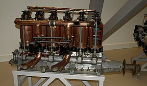
....which would make this aircraft more likely an FE2b:

.............:-)
-
Not much although the plywood packer gave up and I had to find a piece of steel to finish it off.
Thanks for the offer Andy. I have a ball turning attachment for the Myford which I bought to do the Dennis ball joints. In the end, we found enough good ones to do the job so it has never been used. I am looking forward to having a go when the steel turns up!
Steve
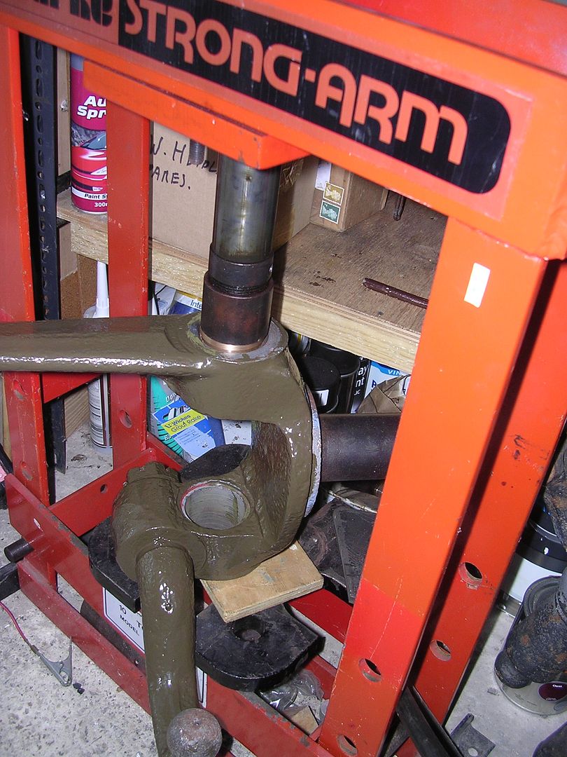
i was thinking more along the lines of the open end of that forging being unbraced/unsupported....whilst applying pressure to sit that bushing in....:-)
-
I wouldn't dismiss the Be2 so fast - it was very good at what it was designed for.
It just wasn't designed for aircraft vs aircraft fighting and sadly they kept using them for years after it was obvious that air warfare had evolved........
However, there are some in the country that might be available to be towed/disassembled -
http://ww1aviationheritagetrust.co.uk
This pair just moved to Bicester.
Not surprisingly there was an inquiry into why such hoplessly obsolete aircraft were still at the front.
one of the main drawbacks with the Be2 was that in order to maintain its centre of gravity it required the layout of the observer sitting in front of the pilot. This coupled with extensive wire bracing for the high bay wings...and its poor climb rate & altitude performance left it very vulnerable to attack...particularly from below and to the rear...where the observer had to stand up and fire over the pilots head to the rear....
If bombs were to be carried then the observer had to be left at the airfield.
It did enjoy a brief new lease of life though protecting London on the home front.
Albert Ball summed it up as a "bloody awful aeroplane" ....although it did have inherent stability....a good quality for observation and aerial photography duties etc..
-
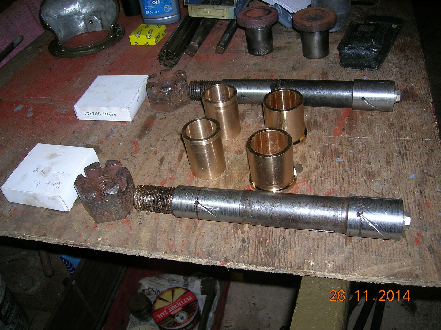
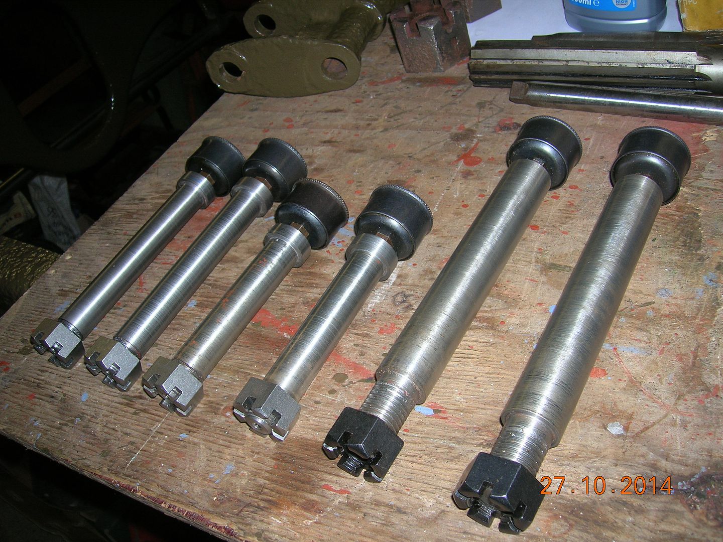
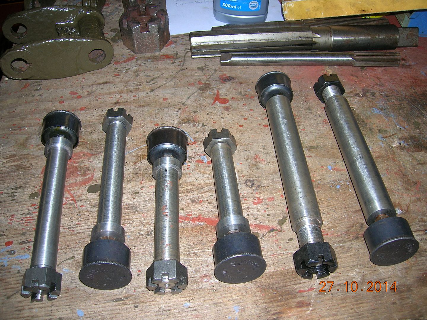
how much force was required here?...not too much i hope....Our target each Christmas is to reassemble something significant and this year is no exception. We want to get the engine sealed up and ready to go in and also fit the front axle and stub axles. To that end, Father has been pressing on with the stub axles and has turned up some new bushes to match the skimmed king-pins.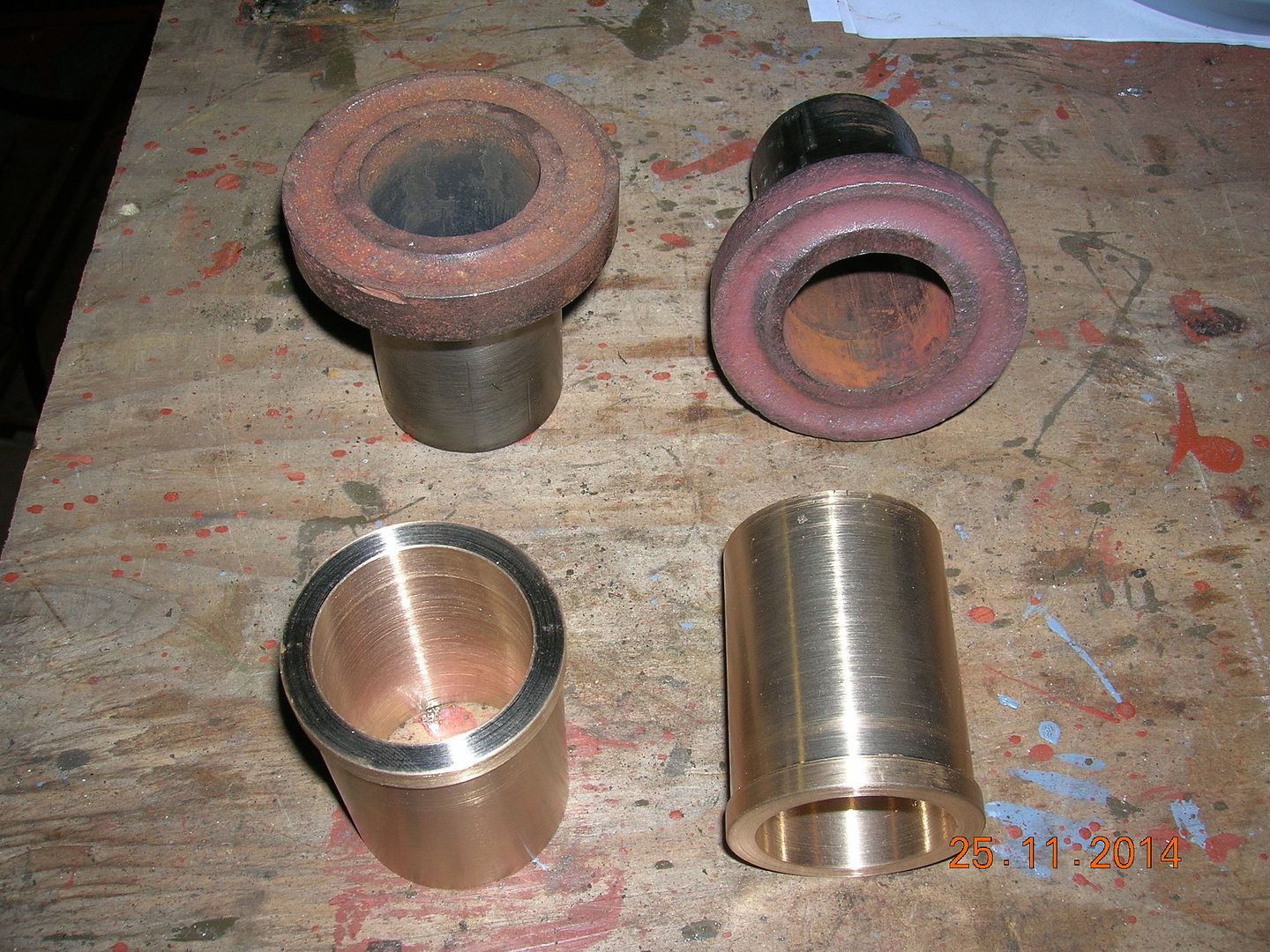
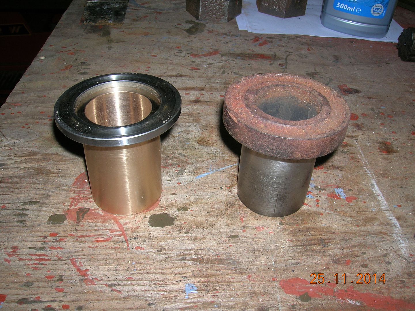
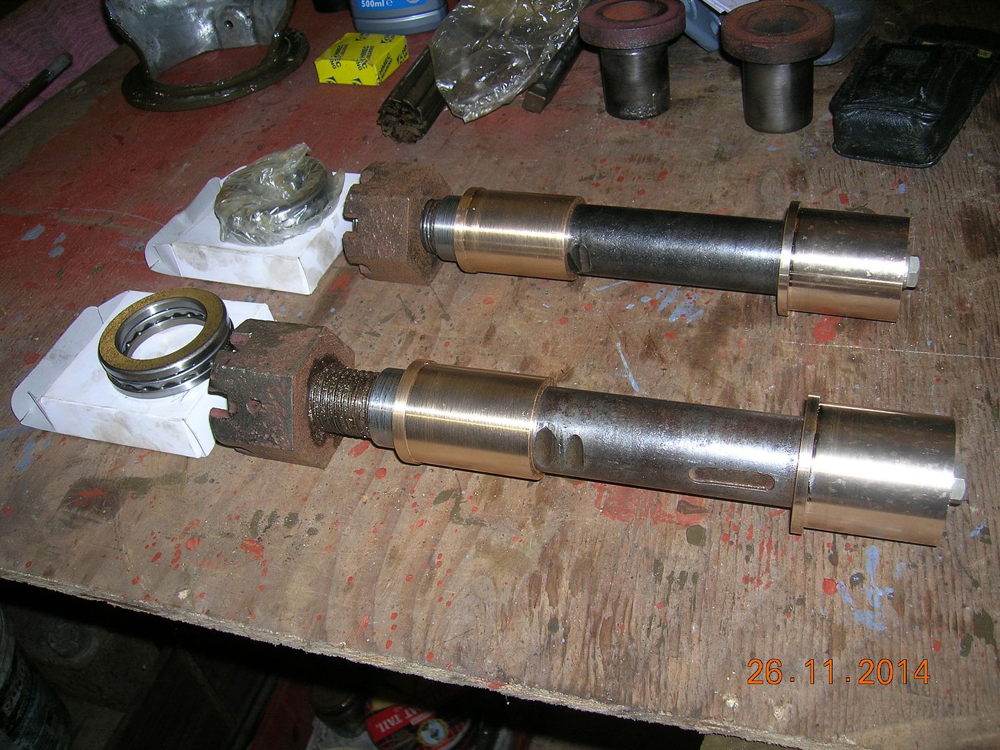
The original top thrust bearings were part of these bushes but, unfortunately, are rather beyond salvage.
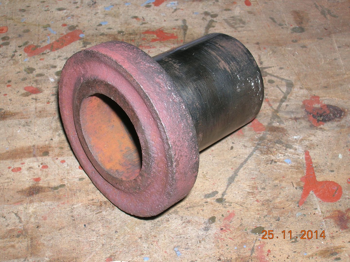
Not surprisingly, they proved unobtainable to replace so Father has turned up plain bushes with a shoulder to suit a modern thrust race as well as the more conventional plain bushes for the bottom.
Steve pressed these in using his 10T press in a remarkably small space on the garage floor.
-
side valves are sloggers though....That's an interesting article Flandersflyer.Wikipedia states that only 7 out of 140 devices tested under strict conditions improved the engines efficiency. Of course the designers and manufacturers knew this but their continuing sales relied on the fact that no man would admit that he had been duped by a fuel economy device.
I the early days of motoring history carburettors were very basic and the old up-draught types did waste a lot of fuel due to the inefficiency of their design so Hulley’s device might well have made some slight improvement at that time.
I remember that the Ford 100E of the late 1950’s had a Solex or Zenith carburettor and the Austin /Morris vehicles had the brilliant SU carburettor and the difference in the fuel consumption figures was surprising. The A35 and the Morris Minor could easily get 40mpg whilst Ford’s 100E could barely get 30mpg.
I can remember Ford’s efforts in trying to keep pace with Austin/Morris. Ford’s 100E economy device was a button fitted in the floor right next to the throttle pedal. With the natural position of the foot pushing down on the pedal it would contact the button and stop the throttle being pushed more than half way down. To accelerate harder meant an awkward twisting the foot to one side to bypass the button. Later the 4 cylinder ‘V’ engined Ford Transit was also a thirsty beast, about 18mpg - less with a big load, and Ford attempted to overcome this by fitting an upright facing tee in the fuel line next to the carburettor and taking a pipe back to the petrol tank, the idea being to relive the pulsating pressure of the mechanical fuel pump on the float needle valve. I presume it must have worked to some extent as Ford fitted it to some of their other engines.
Eventually Ford brought out their own carburettor roughly based on the SU but in order to get around the SU patents it turned out to be a right abomination and was eventually only fitted on the 2ltr Cortina Mk5 ----- I think.
John
Please note.
As pointed out by Sean N below. The 100E had a 1172cc side valve engine which by its design would certainly had a high fuel consumption. I should have said 107E (Prefect) which had the body of a 100E but with the 997cc overhead valve engine that was later fitted to the slope back windowed 105E Anglia.
-
theres a wikipedia on the subject...here:The manifold gasket device reminds me of a group of articles that come under the general term of Fuel Saving Accessories. Over the years many weird and wonderful designs have been produced, none of which worked other than for the intended purpose of making the seller rich.Each time there was afuel price rise another batch would come onto the market. Most were designed to be fitted in the inlet side and comprised of gaskets containing spiral air bleeds to swirl the mixture or brass gauzes to break up the fuel droplets; others consisted of a venturi shaped to accelerate and swirl the fuel mixture.
Once the inlet side had been saturated they started on the exhaust side. One expensive design was the ‘Jefferator’ and this mushroom shaped thing screwed into a hole tapped into the exhaust manifold and it was designed to bleed air into the exhaust stream. Another expensive design was a chromium plated tube with a swirly fan inside that fitted on the tailpipe, it looked good even if it didn’t save any fuel.
Speaking of swirly things I wonder if your device originally had fan blades fitted on the shaft and was designed to swirl the mixture and break up the fuel droplets. Engines burnt a lot of fuel in the early days so anything that would improve the efficiency, however bizarre, would no doubt have been tried.
The new transmission brake shoes look really great; machining them should be an interesting project.
John
-
Sorry to hijack your thread, Ben but here is a pic of the McCurd which we took to Bletchley Park today. (We got very wet on the way home!). Can anyone tell me how many McCurds were used by the ASC? I know that they had at least one but have never seen any documentary evidence other than a single photograph.
Cheers!
Steve
[ATTACH=CONFIG]65582[/ATTACH]
-
He then reversed it and did the opposite end, skimming only the bearing surface.
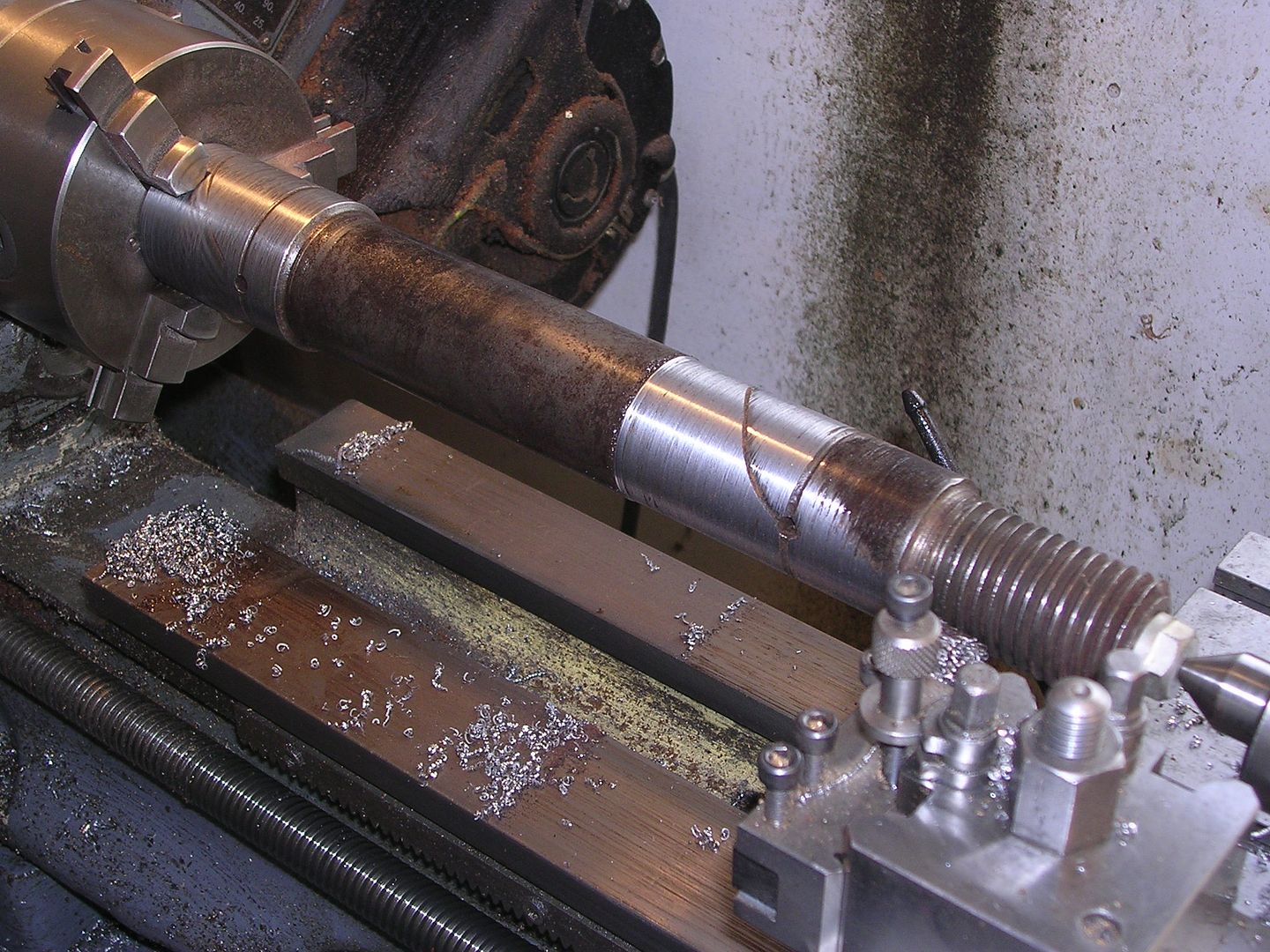
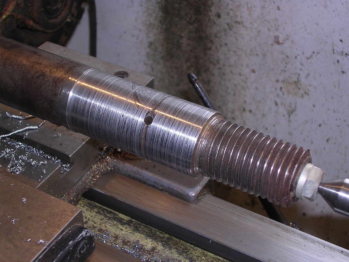
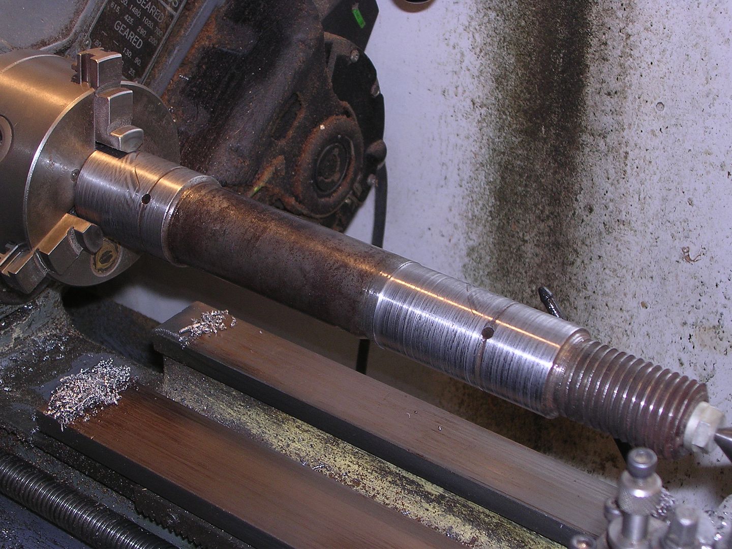
Whilst doing all of this, he found why the bottom end was worn so much more than the top. The grease hole did not go right through the pin so only the top was lubricated! To remedy this, he set the pin up once again and drilled through from both ends using a long-series drill. As you can see, he stretched the capacity of the poor old Myford once again! That done, the grease grooves were re-dressed using the Dremel grinder and the pins were finally complete and ready to fit back in the axle.
i suppose an alternative (on a lathe with a bigger headstock bore) would have been to use a roller box....
-
well...it wouldn`t have helped it much....the BE2...or the "querk" as it was known as ...was a bit of a flying joke really....took very heavy losses during `bloody april`.....nope, the best place for it is definately on the ground...Maybe a wing or two may be an easier task/trailer load in the short term per the set up in the attached image. Rod
-
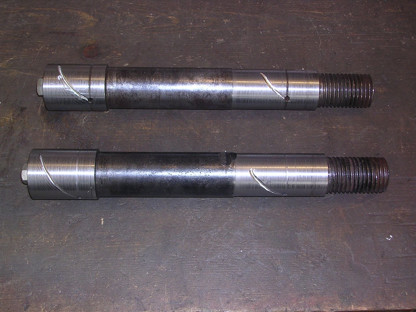
Too many distractions at the Devon end have slowed progress up down there but all six shackle pins for the back springs have now reached the same stage. All that has to be done now is to machine spanner flats, drill cross holes for lubrication and holes for feathers and split pins.
would you not case harden these then?...
-
unfortunately it goes on closer to home as well.......
both HMS invincible:
_British_Battleship.jpg.5df26ace04b3aec9f3ce4baadb5c91bd.jpg)
and HMS indefatigable:
.jpg.eba4d9ace8f6e1433f3c907507b0f2d0.jpg)
have recieved unwelcome visits from "collectors"....
both these ships went up in titanic explosions at jutland with very heavy loss of life...and as such are designated war graves....
-
Theres a radial drill virtually identical to the one in the pic at the national coal mining museum at caphouse colliery between wakefield and huddersfield....
theres other machine tools there as well.....nearly all line drive stuff......
-
Remember this was a day and age when air cleaners were rare indeed and engines were not far removed from the "total loss" oiling systems. Some T-head manufactures did provide protection for the valve gear - Sterling hid their valve stems and guides behind covers in the blocks. Wisconsin used cylindrical aluminum shrouds on some of their engines that enclosed the stems and springs. Rather than keep out dust their purpose was to contain the "oil mist" blowing up through the lifters to lubricate the valves.
Once again... magnificent work.
is that so?...
think rotarys my friend...
-
you can use a stick welder to unfreeze stubborn bearings....
should work the same for tricky bolts, nuts etc....
-
i thought it were like soft jaws....where you get a billet clamped in, swing it and bore out the jaws to suit an O/D...I hope the next bit comes along soon, not sure if I can stand the suspense !Does anyone know of a set of bolt on jaws like the ones that Steve was using. I have a faceplate for my big lathe but no four jaw and have been keeping my eyes open for a set of bolt on jaws for some time with no result. They seem to either get scrapped when businesses close or are suddenly made of gold. Same with big four jaw chucks - my lathe has a D1-11 Camlock fitting and can take up to 4' diameter in the gap so a chuck 30" diameter or over would be ideal if anyone has one in a corner somewhere.
Thought it was worth asking....
David
-
it looks like a gun....:cool2:Here is something interesting ww1/ww2? - still there?[ATTACH=CONFIG]96418[/ATTACH]
What is it?
-
depends on how much carbon was in there to start with...It's just machined and heat-treated steel. How hard can it be?A lump of Silver Steel machined and heat-treated would almost certainly last well enough for a vehicle not actually driving two shifts all week.
(I could have a go if you want, but I suspect that Steve will spot the thrown gauntlet at this point :-)
-
You are too kind. I am just a backyard bodger who manages to get the required result in the end. I am not brave enough to set up my own foundry. I shan't live long enough to do everything!
John. That is quite some trip. I am so pleased that you have got the right wheels. They will really make the job and are undoubtably a boost to morale as well. We are looking forward to seeing the finished job, whenever!
Did you get a picture of the four wheel drive tractor or can you remember what it was?
Cheers!
Steve
Hmm...
not an accurate description really Steve...
caus anybody who has acheaved what the team have done down there in Devon isn`t `bodgin`......theres thinking on your feet, machining work, fabrication, joinery, working with canvas etc....
its got the lot really....hasn`t it...
Glenn.
GLMelectrical.
-
got them links to work...


_British_Battleship.jpg.5df26ace04b3aec9f3ce4baadb5c91bd.jpg)
.jpg.eba4d9ace8f6e1433f3c907507b0f2d0.jpg)
WW1 Thornycroft restoration
in Pre WW2 vehicles
Posted
find a way of fixing the 2 blocks together with the tapers facing each other....then swing them and get an O/D for size...
should make extracting the spun form easier....if you use a bit of allthread epoxied into one of the oak blocks....you can then use a nut to hold the other one to it....get the nut chuckside....then you just back the nut off....and the form should release...thus allowing extraction of the spun part....