


Bibulgomme
-
Posts
9 -
Joined
-
Last visited
Content Type
Profiles
Forums
Gallery
Blogs
Events
Articles
Store
Downloads
Posts posted by Bibulgomme
-
-
Today ,I continue my investigations with an many electrical mesures and control to determine a basic wiring diagram
FOR
UNIT PERSONAL COMMANDER
5820 99 117 4349

Mesures and control on CPU: (radio selector= RIC,RA,RB,RC and monitor switch O or Ø)
Side Connector 7pt-F Audio Connector 10pt-M Commander
Aa Intercom microphone +VE
Ba Intercom microphone –VE Ec
Da Left earphone Bc
Ea Earphone and PTT ground (if RIC=Kc; if RA=KcJc ;if RB=KcAc ;
if RC=KcJcAc)+IfØ=CcFa PTT when 1600ohm to ground NON Connected
Ga Right earphone ifO=Bc ifØ=Dc
Hypothèse déduites:
Connecteur 10 pt-M commander
Ac
Bc left erphone
Cc = K ifØ
Dc
Ec Intercom microphone – VE
Fc
Gc
Hc if Press TT =Kc+Bc ifØ
Jc(10)
Kc(12)
Connecteur 10 pt-M box fixed
Ab
Bb A set micro +ve
Cb
Db
Eb
Fb
Gb
Hb +28 supply
Jb
Kb Earth
what I understand, when I press a PTT of CPU i make i short circuit betwen H and K of CBF.Now, it seems that the CPU is not compatible with my CBF or I am not good cable, perhaps it s nebessary a twisted cable.
do you think there are two CPU systems?
Or twisted cable?
-
Which could be help me is a wiring plan for the commander's cable
and a wiring diagram of CPU and of CBF.
If a member of the HMVF had this in their hat it would be good luck for me
-
Hi,
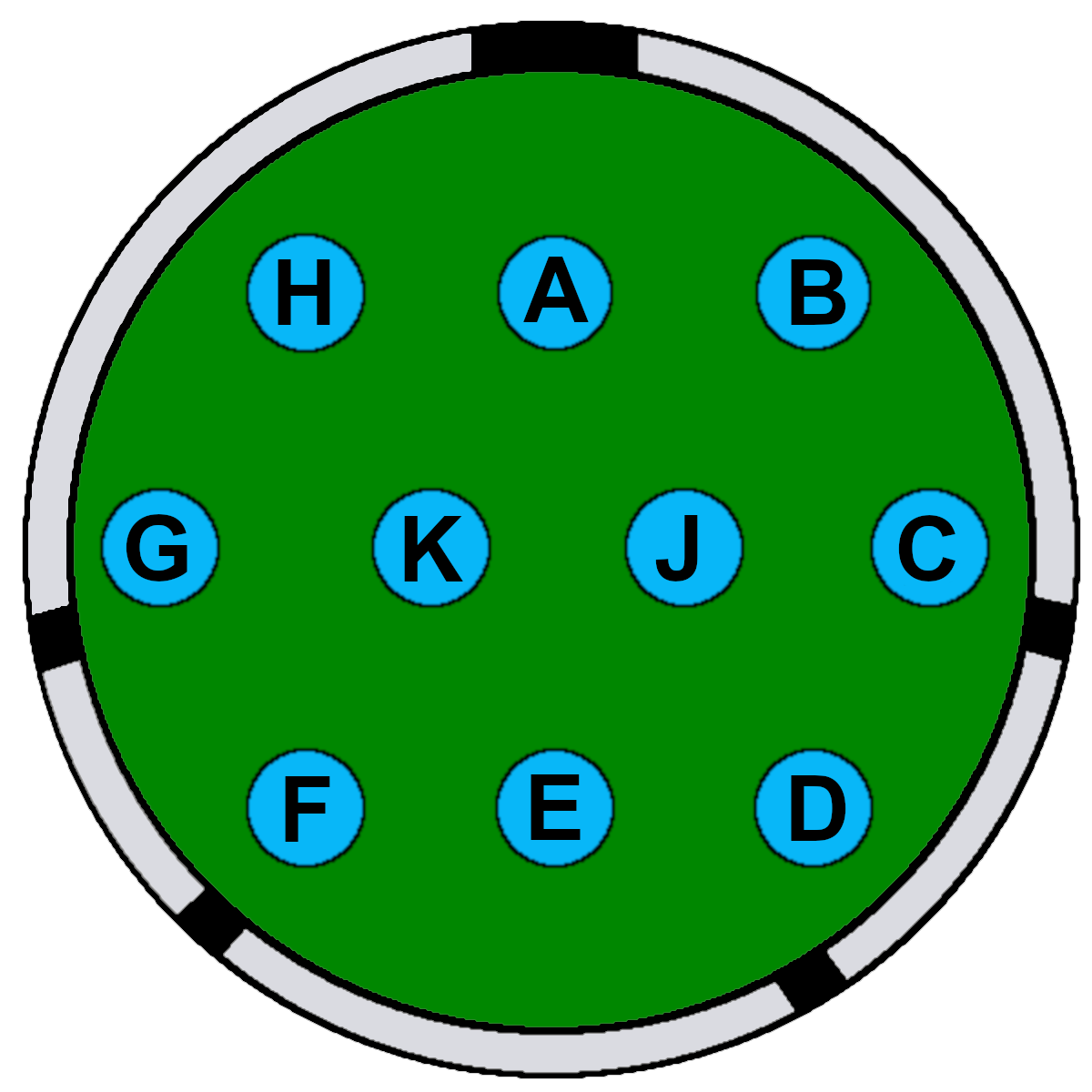
In my Ferret, i have a intercom Clansman with new install CBF (commander box fixed) and a CPU (commander personal unit 5820-99-117-4349) connected with a 10pin cable.


The Commanders 10pt cable was broken

 also I have repaired this pin to pin (A2A; .B2B;..........; K2K;J2J)
Its a picture of my CPU-->

When i connect all, it s OK , I have a 500mA of consumption in circuit, no problem when i turn a CPU's monitor switch or CPU's radio selector .But I have a short circuit fault when i use the press to talk button of CPU. (I have already burnt 2 fuses)
Now for test, I use a laboratory power supply with Amp regulation.
I have make a another test with a new CBF but I have a same fault.
I don't understand the breakdown.
Does somebody have an idea?
Thanks
-
Et encore bien d'autre jouet pour grand garçon adulte dont je ferai des photos ultérieurement Aro M461, Unimog,.....
And many other toys for big adult boys which I will take pictures of later,Aro M461, Unimog, ........Sinon tous les véhicules fonctionnent correctement,
Otherwise all vehicles are working properly,pour l'Austin j'ai déjà refait la mécanique et les freins son neuf avec du liquide au silicone.
for the Austin I have already redone the mechanics and the brakes its new with silicone liquid.Je rénoverai la carrosserie plus tard car maintenant je préfère jouer avec le Daimler Ferret.
I will renovate the body later because now I prefer to play with the Daimler Ferret.
Pour Le Daimler Ferret je fais me contenter de le compléter au niveau radio puisqu'il n'y a que les intercoms non ANR
For Le Daimler Ferret I am content to complete it on the radio level since there are only non-ANR intercoms.jpg.1b987733c1f821d04aa4eec9376eb36a.jpg)


-
 1
1
-
-
petite photo de famille avec la Roayl Enfield (fabrication indienne) au centre
small family photo with the Roayl Enfield (Indian manufacturing) in the center

-
and My MUTT A1


-
J ai quelques autres véhicules avec lesquels je me promène en famille le week quand le soleil brille.
I have a few other vehicles that I drive with my family on weekends when the sun is shining.DKW Munga


-
Bonjour,
Je suis un petit nouveau sur le forum, j'habite la région Lorraine en France et je suis un fier possesseur d'une Austin Champ avec set C12 et d'une Daimler Ferret MK1/2 que je restaure.
I am a newcomer to the forum, I live in Lorraine in France and I am a proud owner of an Austin Champ with set C12 and a Daimler Ferret MK1 / 2 which I am restoring.
J ai trouvé ce forum très riche en information et en partage d'astuce entre propriétaire.
I found this forum very rich in information and sharing of tips between owners.


-
2
-


.jpg.1b987733c1f821d04aa4eec9376eb36a.jpg)


Clansman Personal Unit Commander Fault (resolu)
in British Radio Equipment
Posted · Edited by Bibulgomme
Hi,
happy end of year holidays everyone.
with Foxtrott363 and other friend help's, I understand the problem origine.
I use now a CPU n°5820-99-117-5043 (no ANR) for two radios
In the L807 mod inst No16 the are a Note:
The CPU (ANR) should only used with a CBF (ANR) or CBF (D) (ANR). Use with CBF or CBF(D) Will cause damage to the harness.
The major difference between CBF (black) and CBF (ANR) is H pin fonction to 10 pt plug
In a wiring diagram with no (ANR) CBF and CPU , the H pin is in the 0V
Then when I have should use my CPU (no ANR) in my CBF (ANR), I make a nice short-circuit with the H pin.
My soluce was to transform my CPU no ANR to CPU ANR.
then my first modification has been the wiring diagram n°3 below
the winring diagram n°2 below is a cabling observed.
This modification (digram n°3) run but after talking about it with a clansman specialist. The ANR micro dont like a 24V and it must be run with 12-13V supply only.
Then it's necessary to make a 12 power supply regulator in between H ans C pin.
H=18/24V
C=12/13V
In the CPU (ANR) wiring diagram above, the 13v regulator is in the red circle but it's 1980's electronic.
I replace this by a L7812 regulator with 2 diode 1N4447 for add 2x0.6V and 1x C1 100nF.
yelow paint in the button
Control and test for validation with labo supply in In Volt regulation.
13.2 V between C pin and B pin of 7PT plug headset
all is OK good work.
There are a low current, only 200mA
Thank you again for the help of Foxtrott363 and Clive without whom I would not have found a soluce.
I hope my research will be useful to other users
Regards,