


Andrew Rowe
-
Posts
309 -
Joined
-
Last visited
Content Type
Profiles
Forums
Gallery
Blogs
Events
Articles
Store
Downloads
Everything posted by Andrew Rowe
-
restoration of a valentine MK5 tank started
Andrew Rowe replied to monty2's topic in Tracked vehicles
Once the Main hubs are assembled, the brake components can be fitted to the outside of the hub. Picture shows Drums and Shoes back from getting machined out to run true. They are cast steel, of which I would suspect a fairly high grade. Flange shaft inserted, then brake actuator unit, then shoes and then drum. The shoes are held in by a single pin. When taking the pin out , screw in a 3/8 BSF bolt into it , that is attached to a slide hammer. Rotate the pin 1/2 a turn when this bolt bottoms out in the hole. Using the slide hammer, a few blows and it will extract itself. Cheers from The Tank Factory.


-
restoration of a valentine MK5 tank started
Andrew Rowe replied to monty2's topic in Tracked vehicles
The following pictures show the Final drive hubs being assembled. The inner hub takes a big double ball roller bearing that gets pressed in first, followed by an oil seal , then a spacer, then a parallel roller bearing that has grease and then another seal. This bearing is the outer one closest the brakes and the seals and this greased bearing become the barrier to stop the final drive oil leaking into the brake drum housing area. The planetary hub is lowered into place and then the other inner part of the housing is temporary bolted together. The reason for this is so the brake drum flange shaft can be inserted and the brakes can be setup on the outside of this hub, there is also an internal gear that had to be lined up when inserting this shaft, so it had to be done in this order. Once this is done the inner housing will be unbolted and re- lifted a bit , so it can be sealed with sealant. Cheers from The Tank Factory.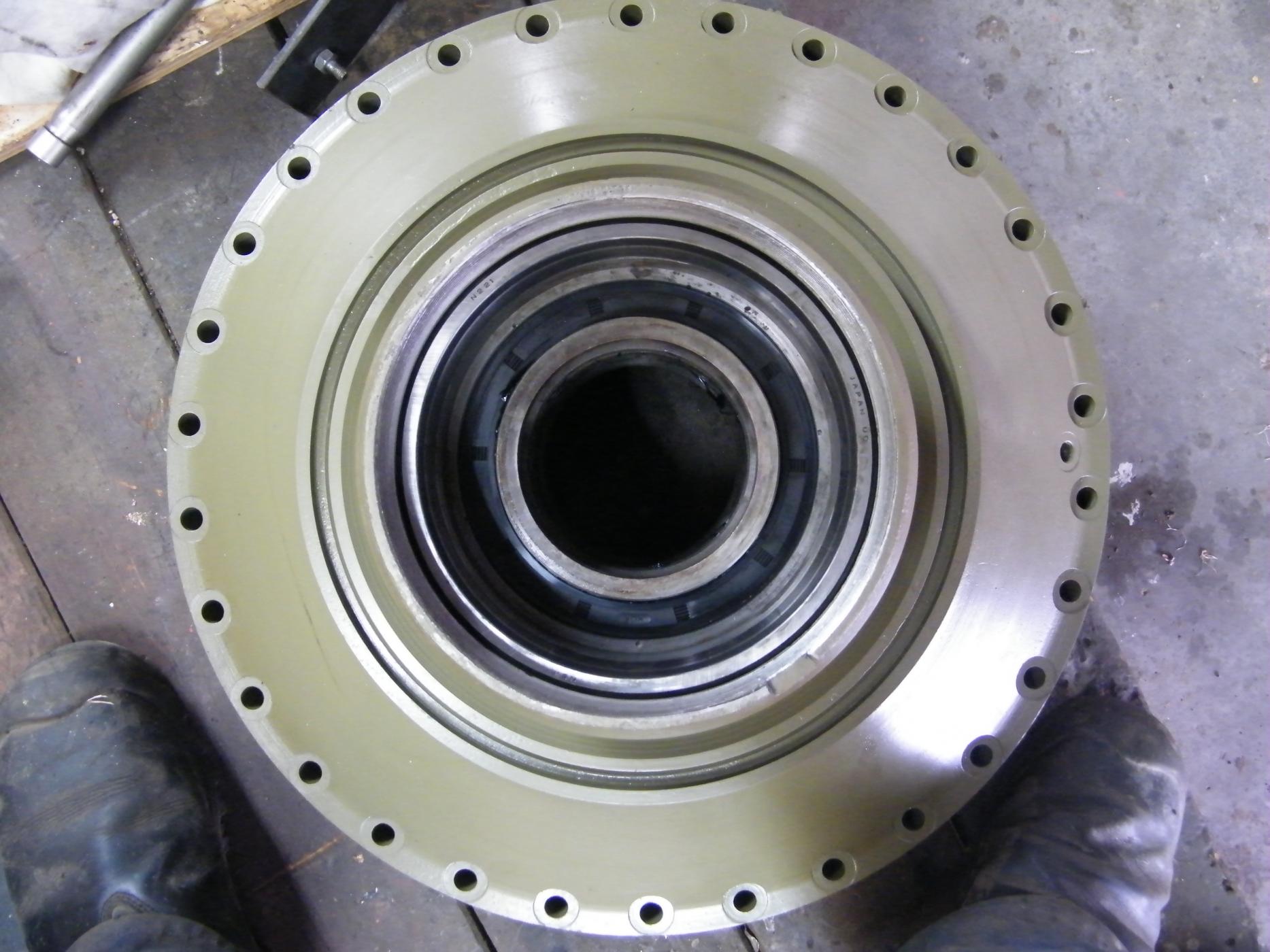


-
restoration of a valentine MK5 tank started
Andrew Rowe replied to monty2's topic in Tracked vehicles
Thanks David, there is currently 2 of us working on the project at the moment. My Trade qualified Mechanic with 30 years experience and myself with 30 years in Heavy Structural Engineering / Construction. We also have a specialist Electrical Engineer that will join us for a hand. We do have a specialist team working on the engine at the moment and the Team leader in that subassembly has 40 years experience and all the gear for engine rebuilding. Currently we are waiting on the new pistons and liners to be flown in from the States. The injectors have all been serviced with new nozzles and tips also. It does help that I have built a 1200m2 workshop , with blasting facilities at hand, and we also have a 40 tonne lifting capacity if we need. Day to day lifting capacity is done with 2 x 5 tonne overhead cranes also which does make life easier. It will be great to see another Scorp down here as our own NZ ones were flogged off to Helston Gunsmiths in Cornwall back in 1998 for $435K for 21 plus container loads of parts that included 50 sets of war reserve track that had never been issued. Cheers Andrew. -
restoration of a valentine MK5 tank started
Andrew Rowe replied to monty2's topic in Tracked vehicles
This coming week, we commence work on the assembly of the final drives. A couple of pictures of the planetary gears. Cheers from the Tank Factory.

-
restoration of a valentine MK5 tank started
Andrew Rowe replied to monty2's topic in Tracked vehicles
We have arrived at the final assembly stage of the gearbox. Main selector housing fitted and outer engaging housing and shaft, cleaned up and fitted with new seal. The Bevel box unit has been bolted on and the crown wheel and pinion have been set up and shimmed for the required back lash and clearances. The top cover is then secured by the 4 main bolts either side of the 2 bearings and also a series of smaller bolts around the rim. Cheers from The Tank Factory


-
restoration of a valentine MK5 tank started
Andrew Rowe replied to monty2's topic in Tracked vehicles
The main brake actuating units assembled , ready to be bolted to final drive hubs. Cheers from The Tank Factory.
-
Is it any thing to do with a smoke discharger? Cheers Andrew
-
Don't be surprised if those little cut outs are for the brake cables to pass through for the rear drums?
-
restoration of a valentine MK5 tank started
Andrew Rowe replied to monty2's topic in Tracked vehicles
Hi John , I see your DD still featuring often. The T no. is 66784 June 1942, there was also a number 3948 on the plate. It was a Vickers build Tank I think . I am sure you could pull up the contract card for me from Bovy!. After collecting Val parts for 30 years it is quite good to have a very large shed full of spares, you never know when you might need them. Cheers Andrew. -
restoration of a valentine MK5 tank started
Andrew Rowe replied to monty2's topic in Tracked vehicles
Final Drives are now all stripped and the housings are being processed. The second pictures shows the main shaft that goes through the final drive and this outer flange is what the brake drum attaches to. Main housings and sprockets are blasted and given a 2-pot epoxy prime. This is our special brew , that is green in colour, so any wearing of the paint surface when the vehicle is in use would only show green. This paint product was used on our America's Cup yachts, so is tried and tested. Great for a DD Tank! Cheers from The Tank Factory.

-
restoration of a valentine MK5 tank started
Andrew Rowe replied to monty2's topic in Tracked vehicles
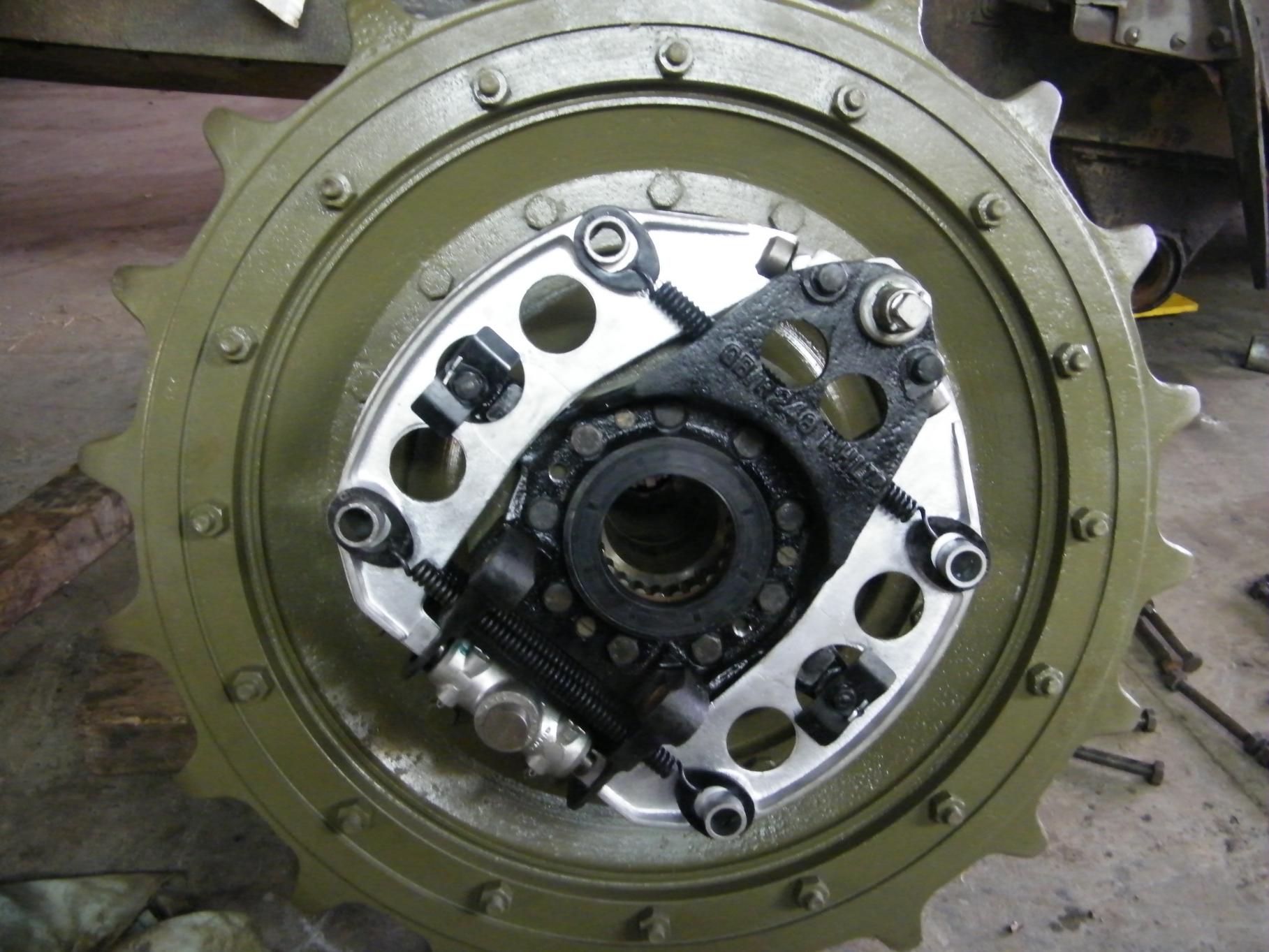
Work continues on stripping and preparing the brake components that are located on the outer face of the final drive hub, and then encased by the brake drum itself. The last pictures shows the brake actuating gear. This consists of a rod that goes through the centre of the final drive hub and when it moves outward by the Heli-hub control lever and actuating mechanism it transmits the 2 wedges to open the brake units to force the shoes into contact with the drum. Cheers from The Tank Factory.


-
restoration of a valentine MK5 tank started
Andrew Rowe replied to monty2's topic in Tracked vehicles
Having received the rest of the Laser cut gaskets back for the gear box, we have commenced the rest of the assembly of it. Pictures show main shaft now in along with oil pump for main input shaft bearing followed by clutch thrust bearing sleeve and then bell housing. Next time work will continue on the Bevel box end which sits directly behind the gearbox and transmits drive to either side. Cheers from The Tank Factory.


-
I do not think that should be a worry about leather / rubber seal, and another tip is to not fill the diff all the way to the level plug, there is no need, and the oil will put less pressure on that seal so it does not leak down the torque tube. The vehicle was probably built on the "total loss system of oil " though! Cheers
-
Have you got a good surface on the pinion nut, for the oil seal in the tube to locate on ,as the diff in the Loyd sits slightly higher than the torque tube and the oil has a habit of leaking down hill !, Cheers.
-
restoration of a valentine MK5 tank started
Andrew Rowe replied to monty2's topic in Tracked vehicles
The 671 Engine has been stripped and has gone through the cleaning tanks. Everything was standard .The crank will get a grind, so we have the new .010 bearings for this, so this will get a new grind in a week or so. We are waiting for the new piston / Liner / ring kits from the USA to turn up soon also. The NOS head has come up great also. Injectors will be sent to the specialist shop this week to be overhauled. Oil pump also gets a new kit. The valves have been dressed and one was found to be slightly bent , so will be replaced. Cheers from The Tank Factory.


-
restoration of a valentine MK5 tank started
Andrew Rowe replied to monty2's topic in Tracked vehicles
Have been away for a week or so, on a "pickin " trip for parts , so we are just getting back into it. The final drives have been split apart and we have all the new seals at hand. We have stripped a few extra final drives as one of the centre brake hub shafts was not up to spec on an oil seal surface, so this will be replaced. Also some better brake components were needed from some of the other ones, even though there are NOS parts, just the time in storage can damage parts. One picture shows the shoes, the pads have all been taken off and are getting new linings and rivets. There are 4 per side, all the same. The drums will get a minimal machine up on the inside face to make sure all is true, and also the shoes will be checked for the radius. All the actuating mechanisms move mechanically by wedges , etc, so there are no seals to deal with in those units. I picked up some of the laser cut gaskets for the gearbox, but there are still a few more coming this week, so will show the completed box when these arrive, Cheers from The Tank Factory.


-
restoration of a valentine MK5 tank started
Andrew Rowe replied to monty2's topic in Tracked vehicles
Leather seals are great , in certain applications, but from MY experience most of our MV vehicles do sit around a lot so if seal surfaces are good, the rubber seal wins every time. Leather seals need to be nice and soft and be rotated regularly, in order that leeking does not start, just MY humble opinion, Cheers. -
restoration of a valentine MK5 tank started
Andrew Rowe replied to monty2's topic in Tracked vehicles
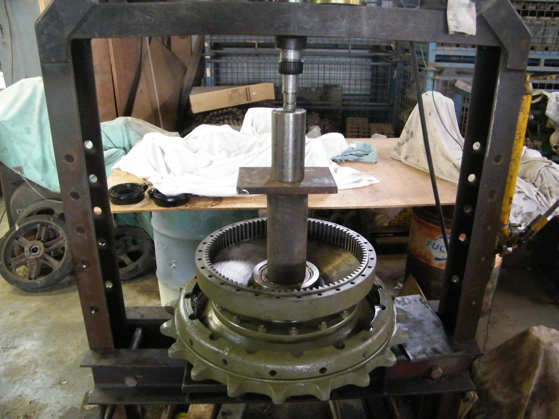
Next on the production line are the final drives. There is a L/H and R/H one, 460kg's each. The difference between the different sides is that the level plug is slightly below centre line, so it is possible to install these upside down if you do not know what you are looking at. The technical term for these units are: Compound fixed epicyclic reduction gear giving 10.214 to 1. This is why, if you have ever noticed a Valentine speeding past, that the Brake drum is spinning heaps faster than the sprocket. I do not know of any other Tanks with this oddity. I would guess it gave the brakes inside the large outer drum more efficiency , and they do work extremely well .Pictures show striping of the L/H unit. It turned out to be a NOS one as it still had the part numbers stencilled on the outer casing , and there is absolutely no signs of wear on the teeth, the machine marks are still there. The R/H one we started to strip , would not release it's brake drum, so rather than fight it, it can go back in the store and I will select another one. The procedure for removing the brake drum, is you undo the outside ring of bolts and then screw in 3 draw bolts, that push off the inner hub face forcing the drum off the shoes. Will replace all seals with new ones as even though the units can be NOS, the old leather seals become too hard and will fail. There are 4 large seals in total per unit. Cheers from The Tank Factory.


-
restoration of a valentine MK5 tank started
Andrew Rowe replied to monty2's topic in Tracked vehicles
Following on from last week, we have all the bearings arrived from the States and we have processed the gear case and have started on the install of the lay shaft and main shaft. The second pic shows the spline to the L/H side that usually gets the most damage from the 1st/Reverse gear meshing onto it . Third photo shows reverse idler installed , after the Lay shaft . Still waiting on the laser to spit out the gaskets, so that will be next week. Cheers from The Tank Factory.


-
Has anyone got a photo or dimensions of the Fuel tank covers for the M3 Stuart. The bases of my one is rotted away and I am trying to figure out how the bottom tray that the tank sits in works. Is it attached to the fuel tank covers or is it a separate item, but still attached some how? Does the Fuel cover go right to the floor?, Thanks.
-
restoration of a valentine MK5 tank started
Andrew Rowe replied to monty2's topic in Tracked vehicles
While we are waiting on gearbox bearings to turn up from the USA, and I am getting all the gearbox gaskets laser cut for accuracy ,and the engine is at the machinists for specialist work, I have made a gig up for compressing the main suspension springs. I have dismantle about 20 to get enough good inner shock absorber shafts for the Tank. It requires 4 in total. The inner shafts are chromed and can get rust spots on the chrome, which is not too good. This Chrome shaft only slides through a bronze housing, and not through any seals, when the suspension is in motion. All the hydraulic dampening for the spring and sealing work is done by another inner shaft, to this outer one. Cheers from The Tank Factory.


-
restoration of a valentine MK5 tank started
Andrew Rowe replied to monty2's topic in Tracked vehicles
After completing the strip out of the other gearboxes , we now have enough good shafts. It was mainly the Mainshaft that gets the damage to the spline, when the big sliding gear 1st/reverse is engaged, if the Tank is not stopped properly it will start wearing the spline away on this shaft, so we selected a shaft with no wear. Pictures show all the gears required in the main gearbox and mainshaft in the vice with 2nd gear being fitted, that also contains 156 little needle rollers , that have to be fitted without losing any! Next is sychro hub and 3rd gear next with a further 156 needle rollers and then 5 gear with 134 needle rollers. Cheers from The Tank Factory.


-
restoration of a valentine MK5 tank started
Andrew Rowe replied to monty2's topic in Tracked vehicles
This week the Engine will go into the engine rebuilder for some specialist work. It is an original Valentine Tank engine. The engine is a GM Detroit 671 model 6004 . We have NOS head / liners / camshaft / new bearings etc for this rebuild, further updates will follow this, from the Tank Factory.


-
restoration of a valentine MK5 tank started
Andrew Rowe replied to monty2's topic in Tracked vehicles
This week we have pulled down the gearbox. The box is a Spicer, made in the USA, 5 speed sycomesh in 2nd and 3rd and 4th and 5th. The early Mk2 and Mk3 Valentine gearboxes were British made and were a 4 speed "crash " box. The box we had for this project had done little work, but I was not happy with the secondary main shaft gear, as where the first and reverse gear slides into the spline teeth on this main shaft ,did have some damage from engagement. This required us to pull down a further 6 boxes to get a shaft that had no damage. We are just awaiting the arrival of a couple of bearings from the USA and then we can complete the reassembly. Special attention has to be paid to the in put shaft seal, as the oil pump that pumps oil onto the front input shaft bearing can bypass this seal and leak down the housing that takes the clutch release bearing, which in turn leaks to the bottom of the bell housing and onto the ground. Here we use a high pressure seal good for 140 psi. Cheers from the Tank Factory.


-
restoration of a valentine MK5 tank started
Andrew Rowe replied to monty2's topic in Tracked vehicles
Hi Robert , the Drive System , you have to remember it is a well designed British piece of engineering, for got to say that the clutch units have "Made in USA" stamped on them! Here is a pic of the drive system, starting with Bevel box behind gearbox in the middle of the Tank, then steering clutch units either side, then heli-hub engaging units either side of these, with flexi-coupling and then onto final drives. All very easy to get to from the rear.


